Downloaded 20 times
![Addressing Signal Integrity in Radar
and Electronic Warfare Systems
2015 Aerospace Defense Symposium
[ Speaker Name ]
Keysight Technologies](https://image.slidesharecdn.com/p9addressingsignalintegrityinew2015final-150602064614-lva1-app6892/75/P9-addressing-signal_integrity_-in_ew_2015_final-1-2048.jpg)
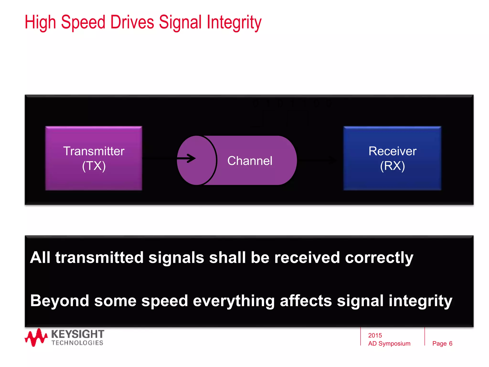
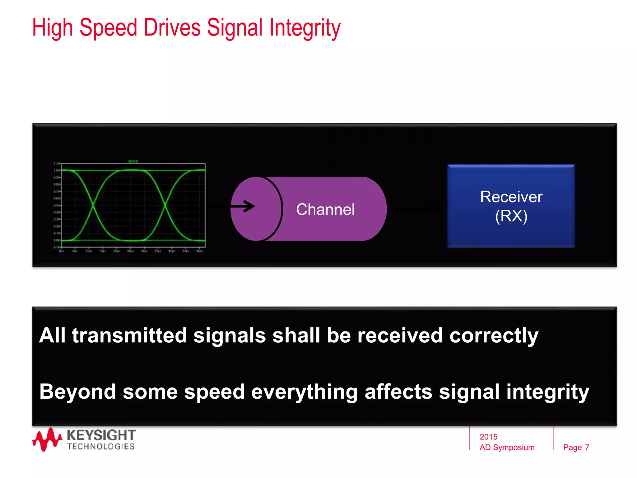
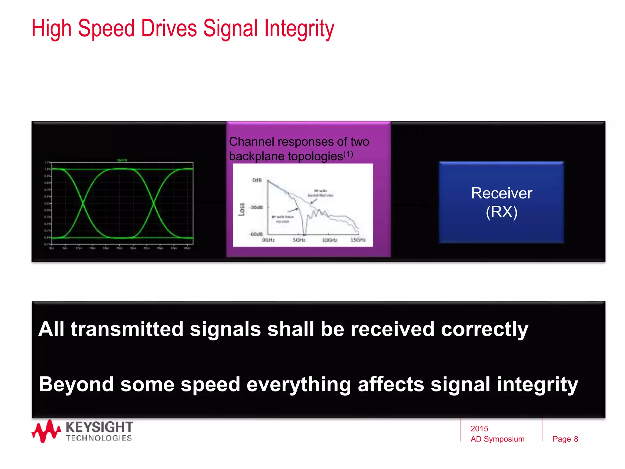
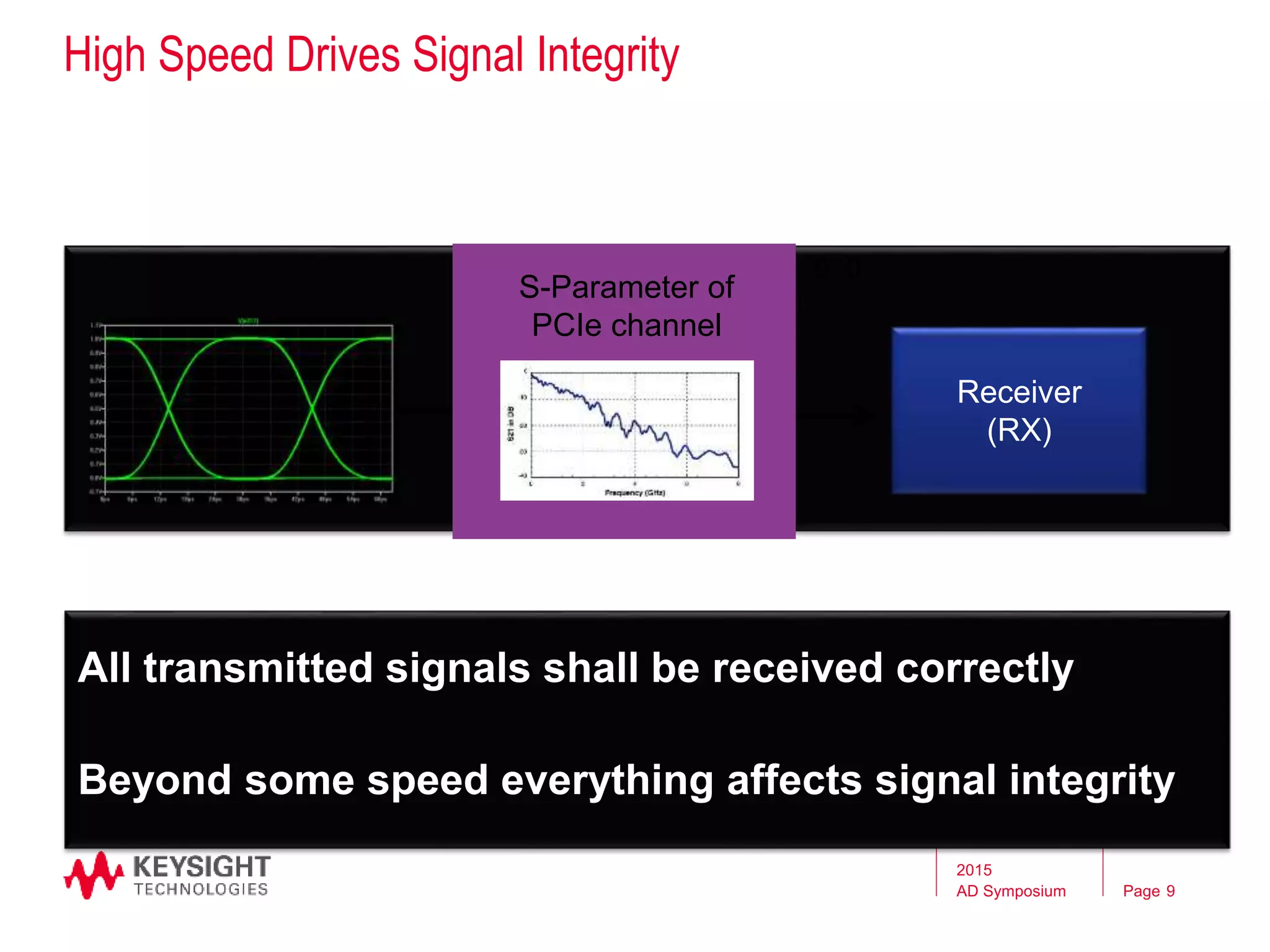
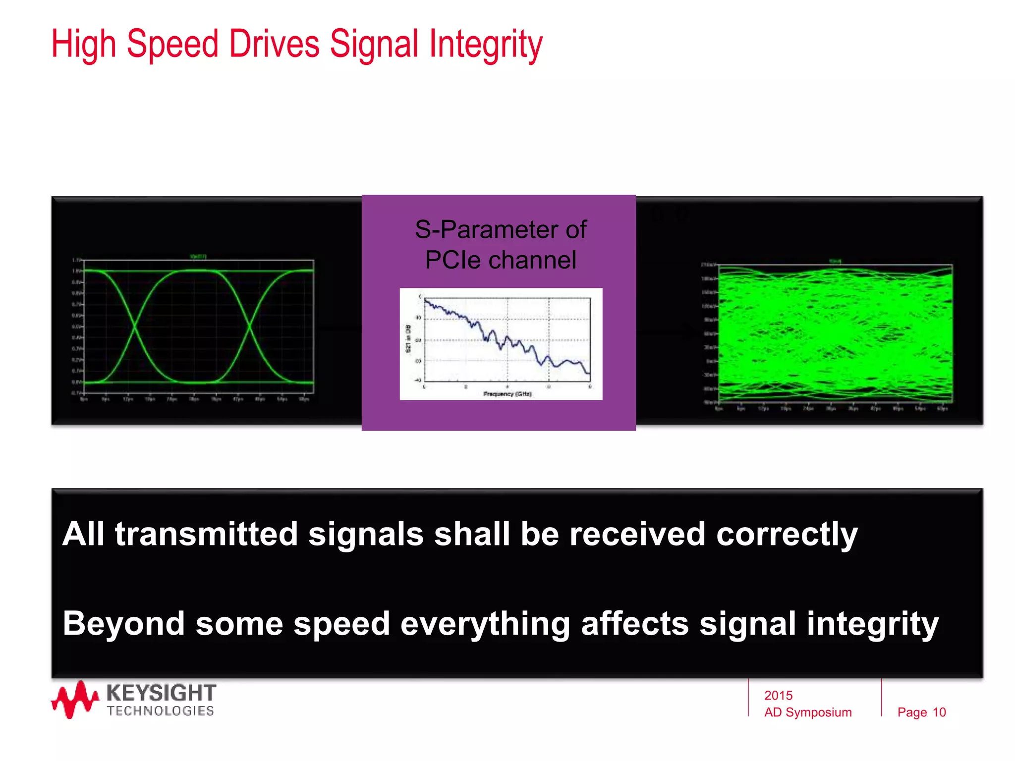
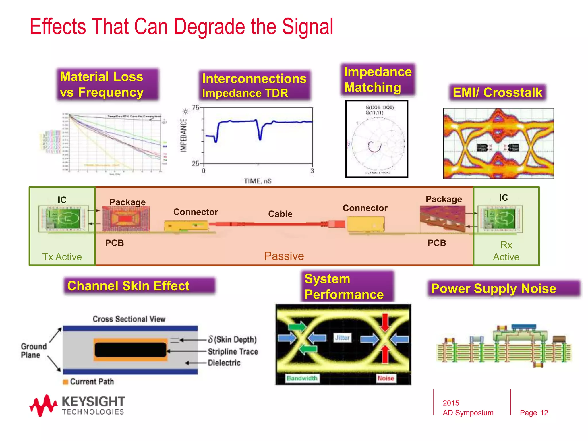
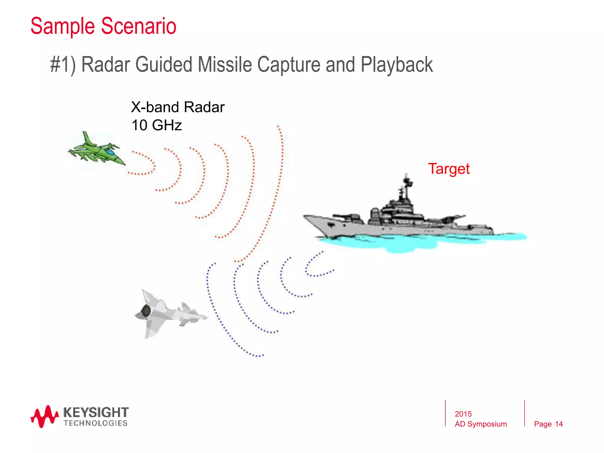
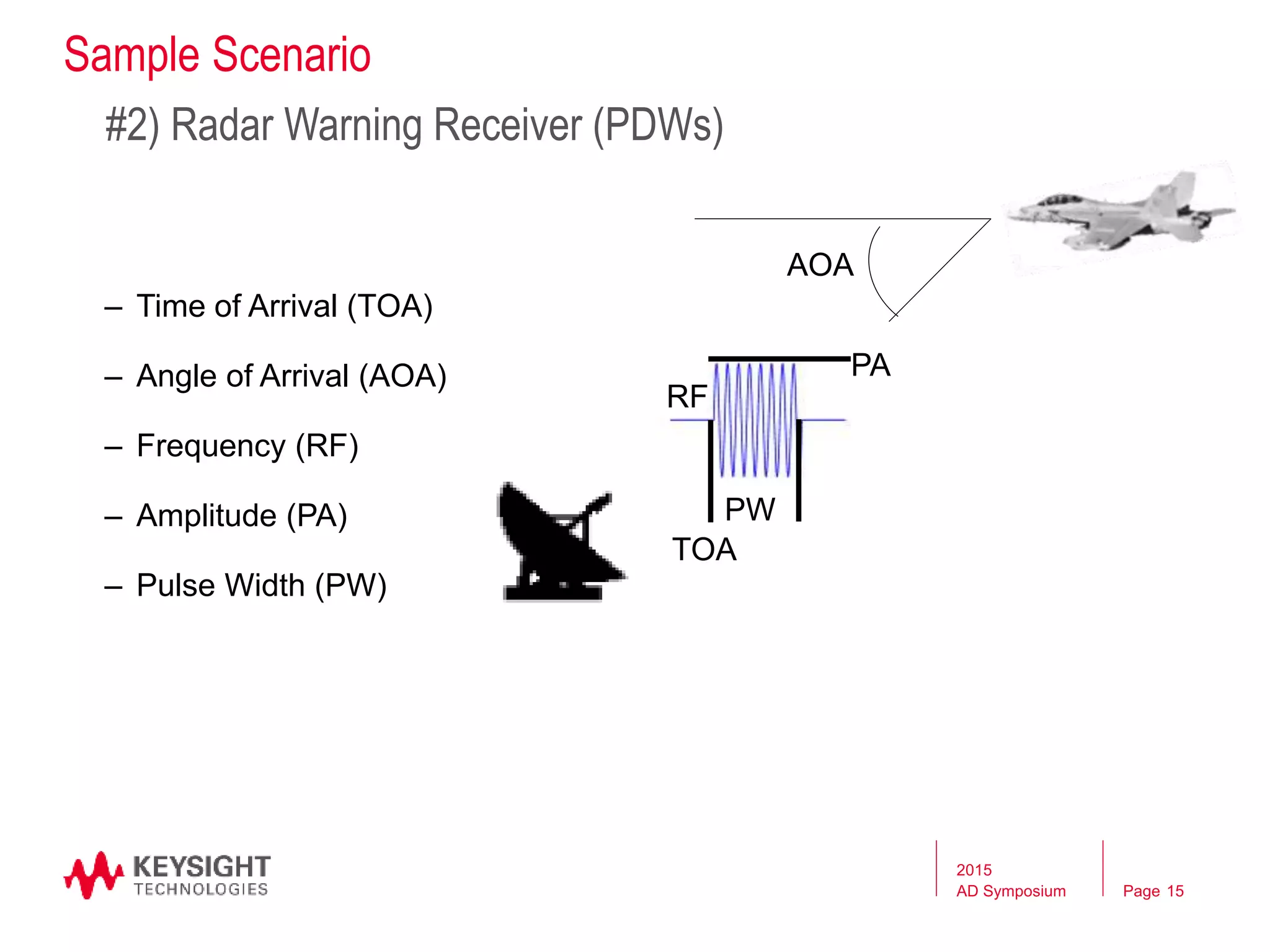
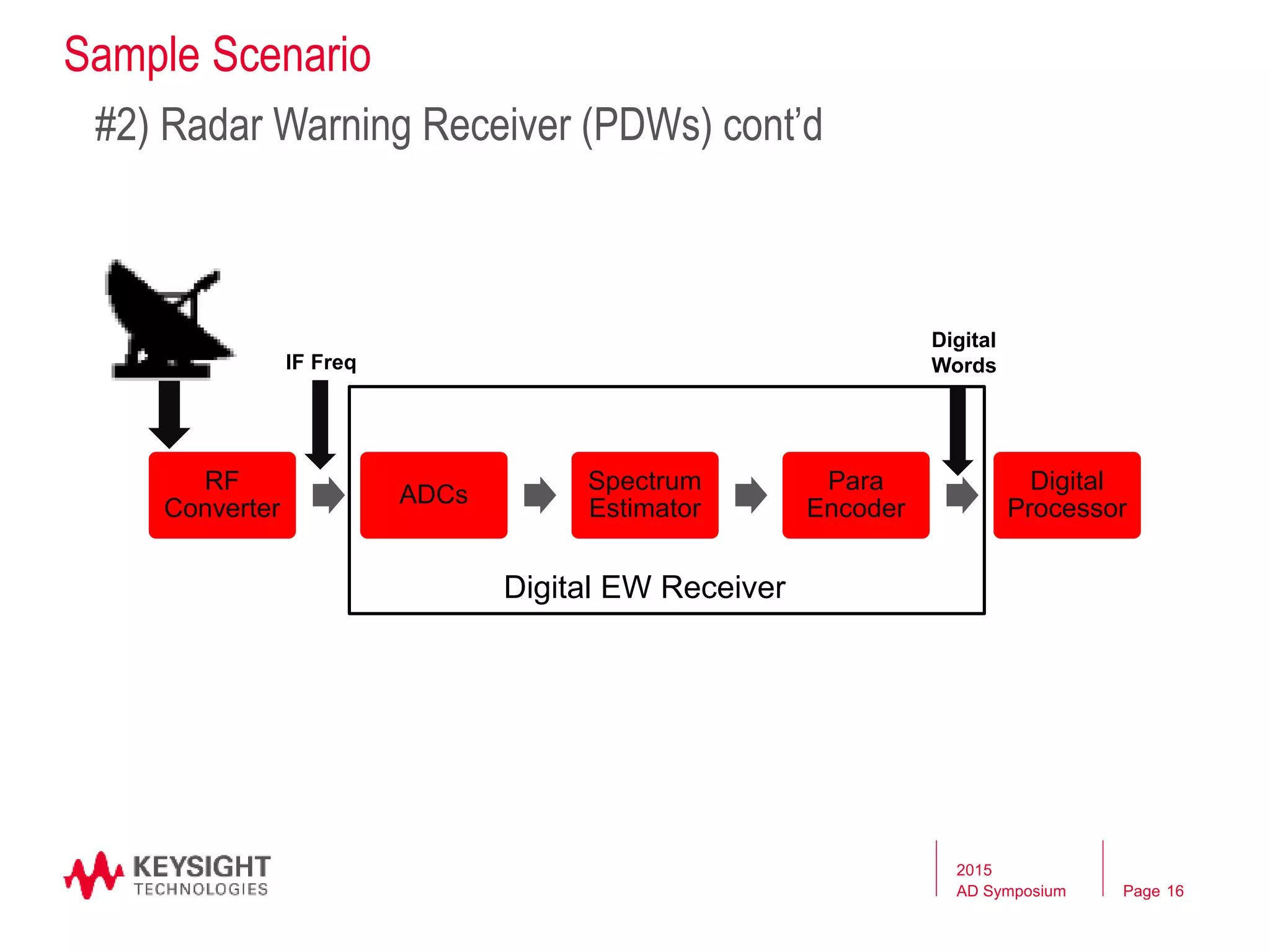
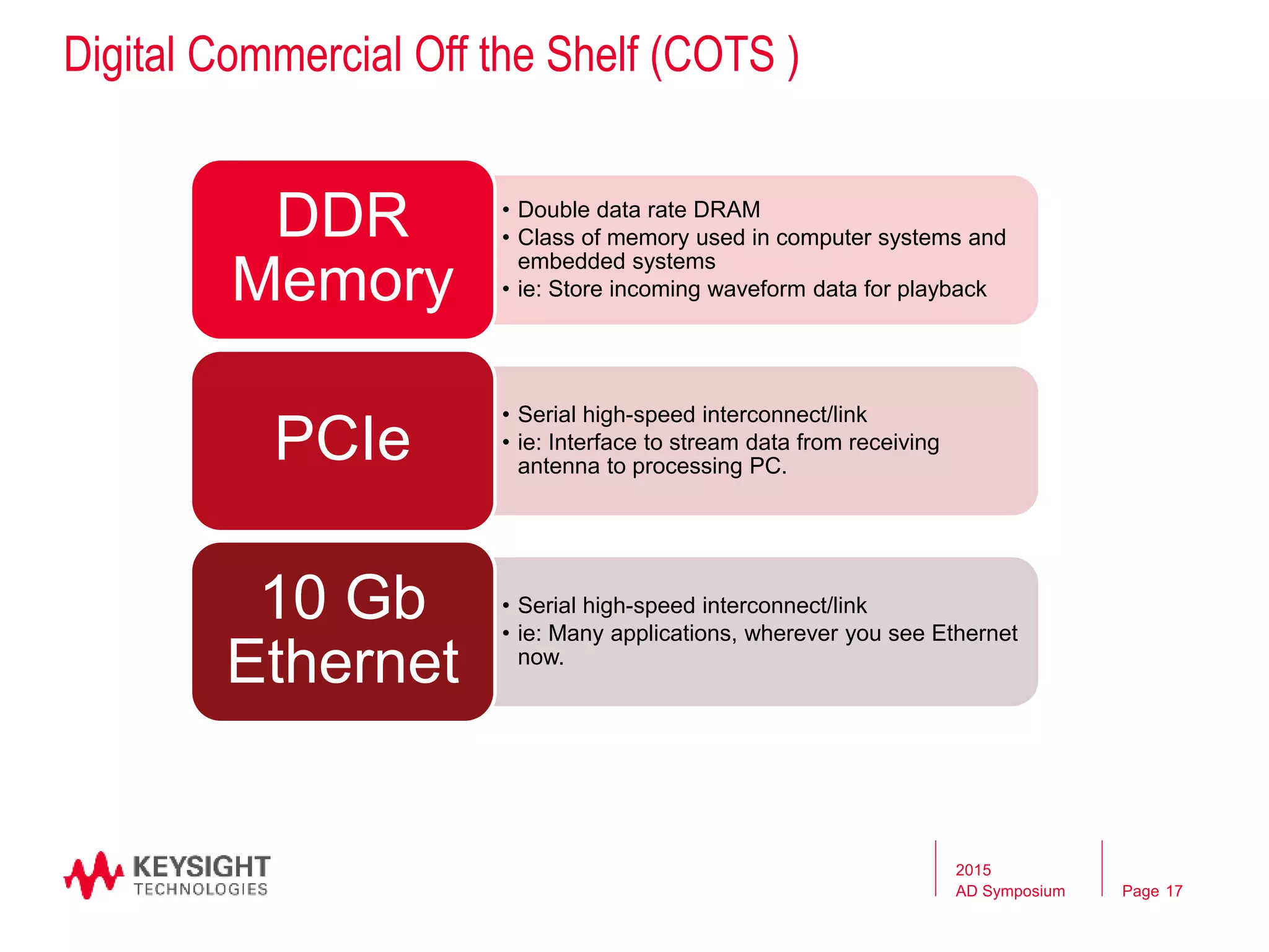
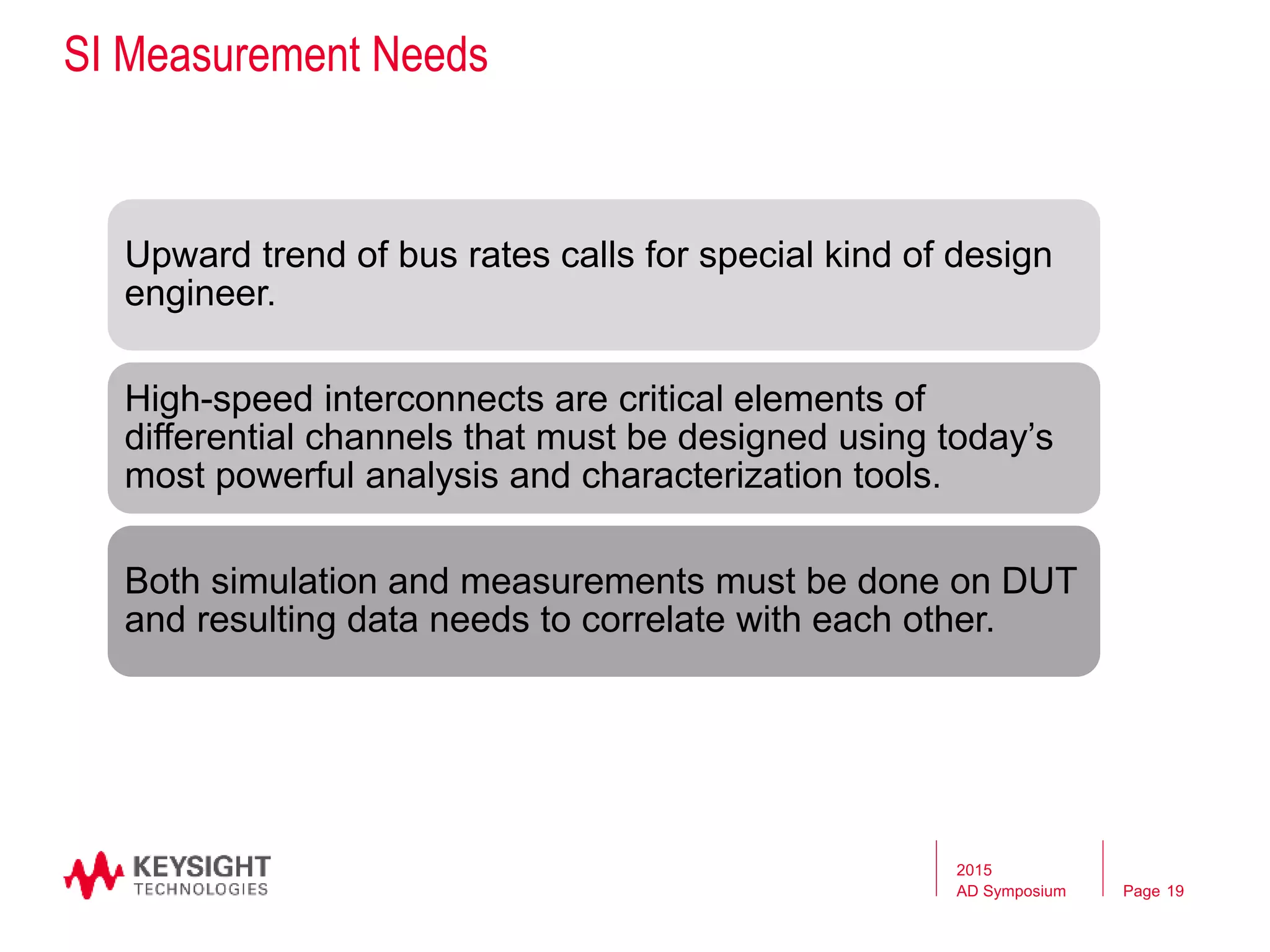
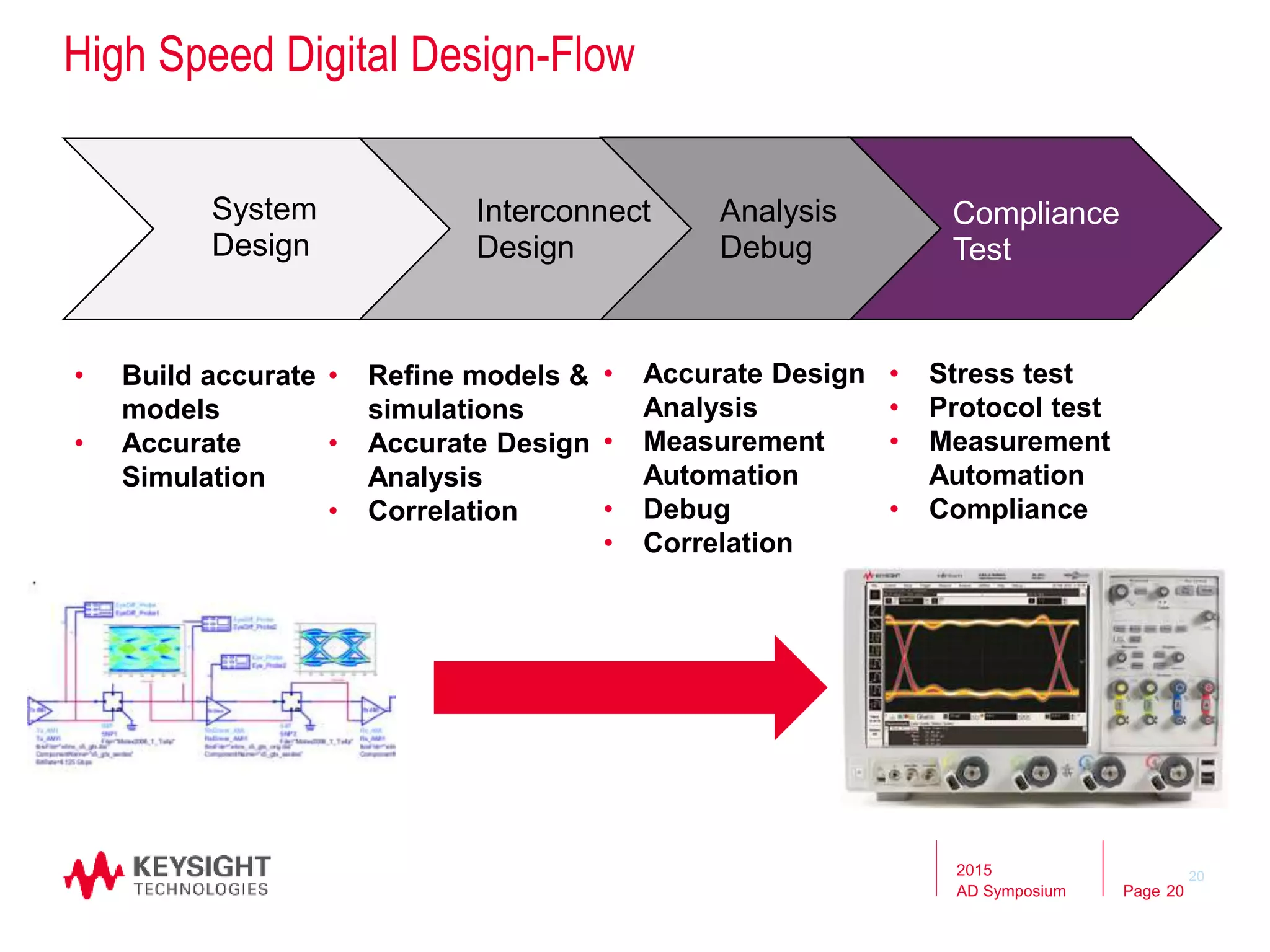
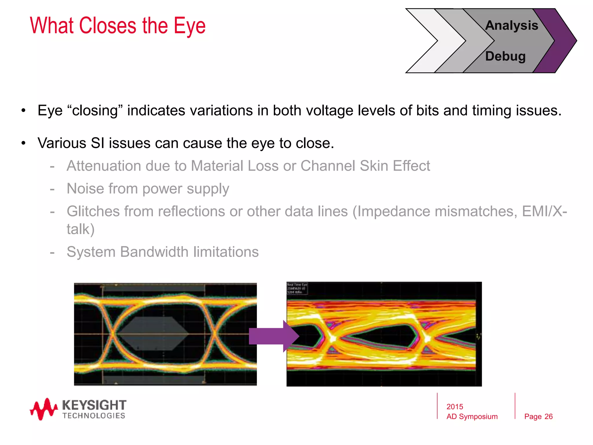
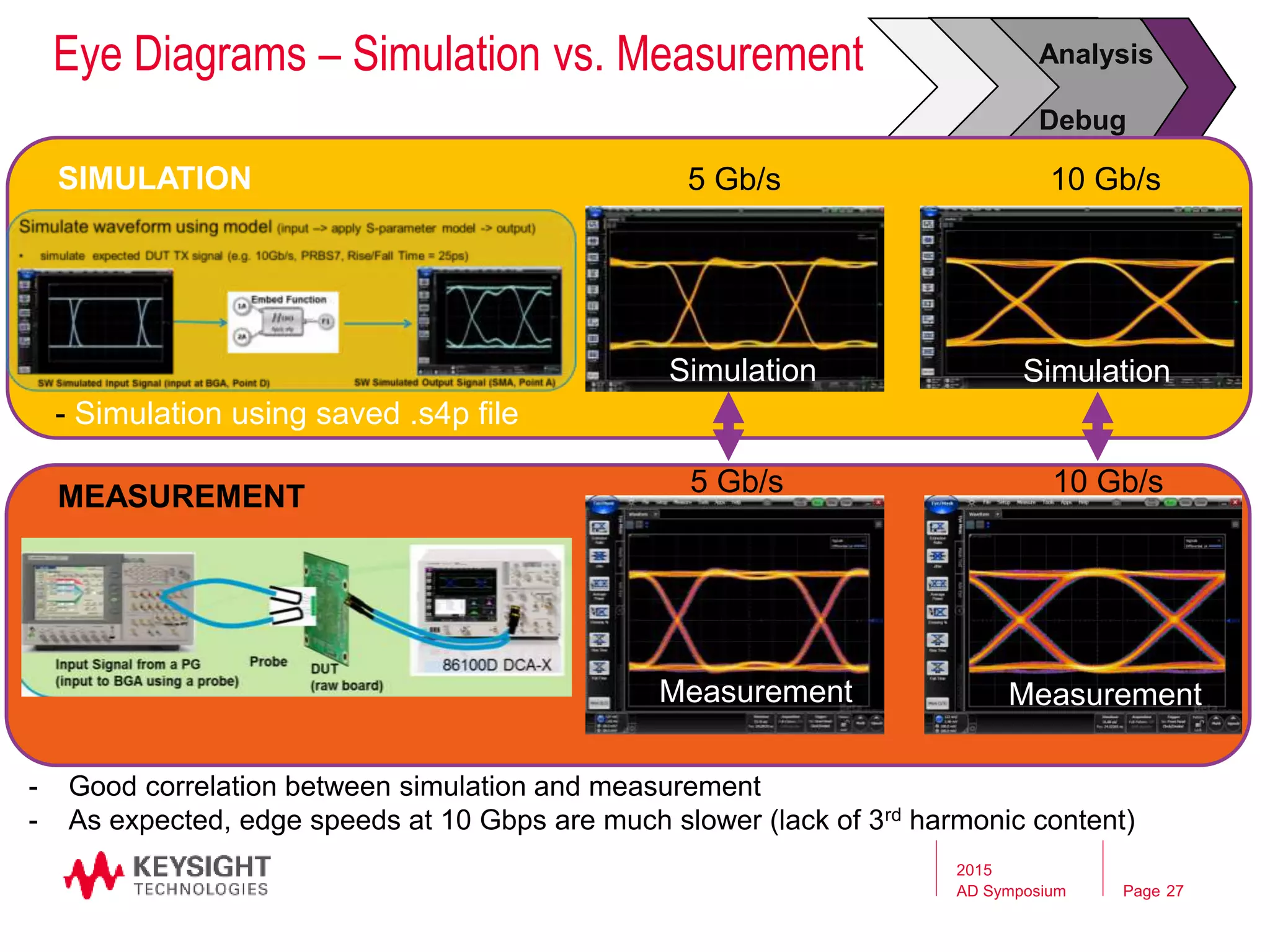
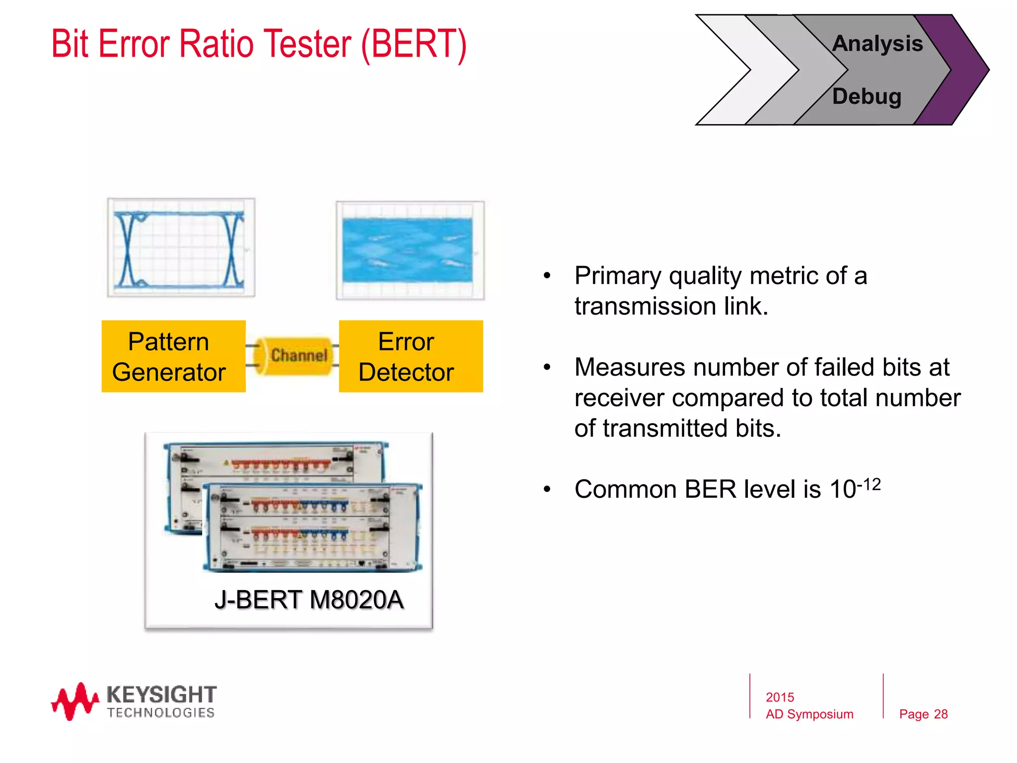

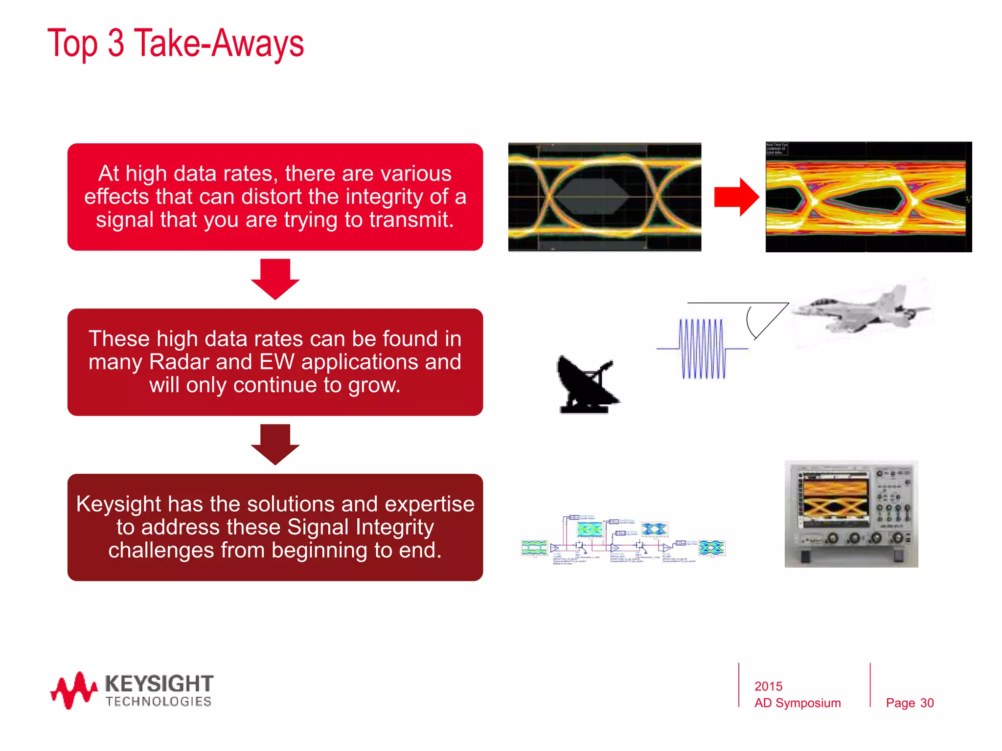

This document discusses addressing signal integrity challenges in radar and electronic warfare systems due to increasing data bus rates. It describes how high speeds can lead to signal degradation through various effects. Measurement and characterization tools are needed to help designers avoid problems and ensure signals are transmitted and received correctly. Simulation and testing of high-speed digital designs is important from early stages of development through compliance testing.


![Signal Integrity - A Crash Course [R Lott]](https://cdn.slidesharecdn.com/ss_thumbnails/1cb0870c-cad3-4a68-ad41-8e9450fec5d8-170217191645-thumbnail.jpg?width=640&height=640&fit=bounds)


