Download to read offline
![Coordinate System of Leg L2 L3 L4 L1 Link Length (m) Range of Motion [deg] Shoulder L1 0 -180° ≦ θ 1 ≦ 180° Thigh L2 1.13 50° ≦ θ 2 ≦ 142° Shank L3 0.77 36.6° ≦ θ 3 ≦ 150° Foot L4 0.39 -47.9°≦ θ 4 ≦ 103°](https://image.slidesharecdn.com/outline2-12730862668246-phpapp02/75/Outline-13-2048.jpg)
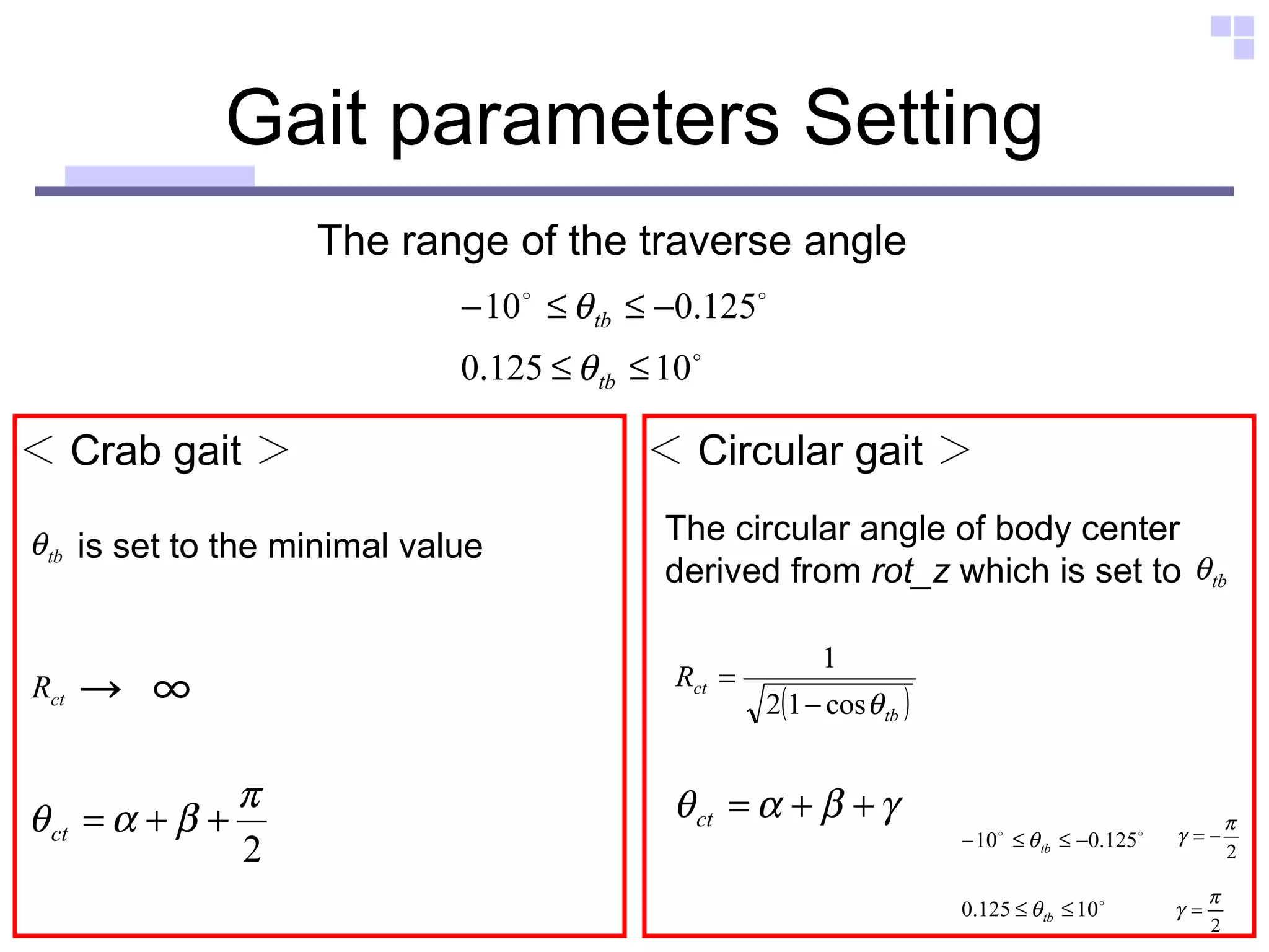
![Omni-directional gait In this system, we applied the trajectory ・・・ “ The Standard Circular Gait” [ * ] “ Low impact foot trajectory” [ ** ] If it is possible to change the body trajectory arbitrarily , we can apply various navigation strategies !! Strategy + [ * ] S.Hirose, H.Kikuchi, Y.Umetani: The Standard Circular Gait of the Quadruped Walking Vehicle, Journal of Robotics Society of Japan, 2-6, 41/52 (1984) [ ** ] Y.Sakakibara, K.Kan, Y.Hosoda, M.Hattori, M.Fujie : Low Impact Foot Trajectory for aQuadruped Walking Machine, Journal of the Robotics Society of Japan, 8-6,22/31(1990) The ability to change the body trajectory arbitrarily at any step during walking is needed.](https://image.slidesharecdn.com/outline2-12730862668246-phpapp02/75/Outline-15-2048.jpg)
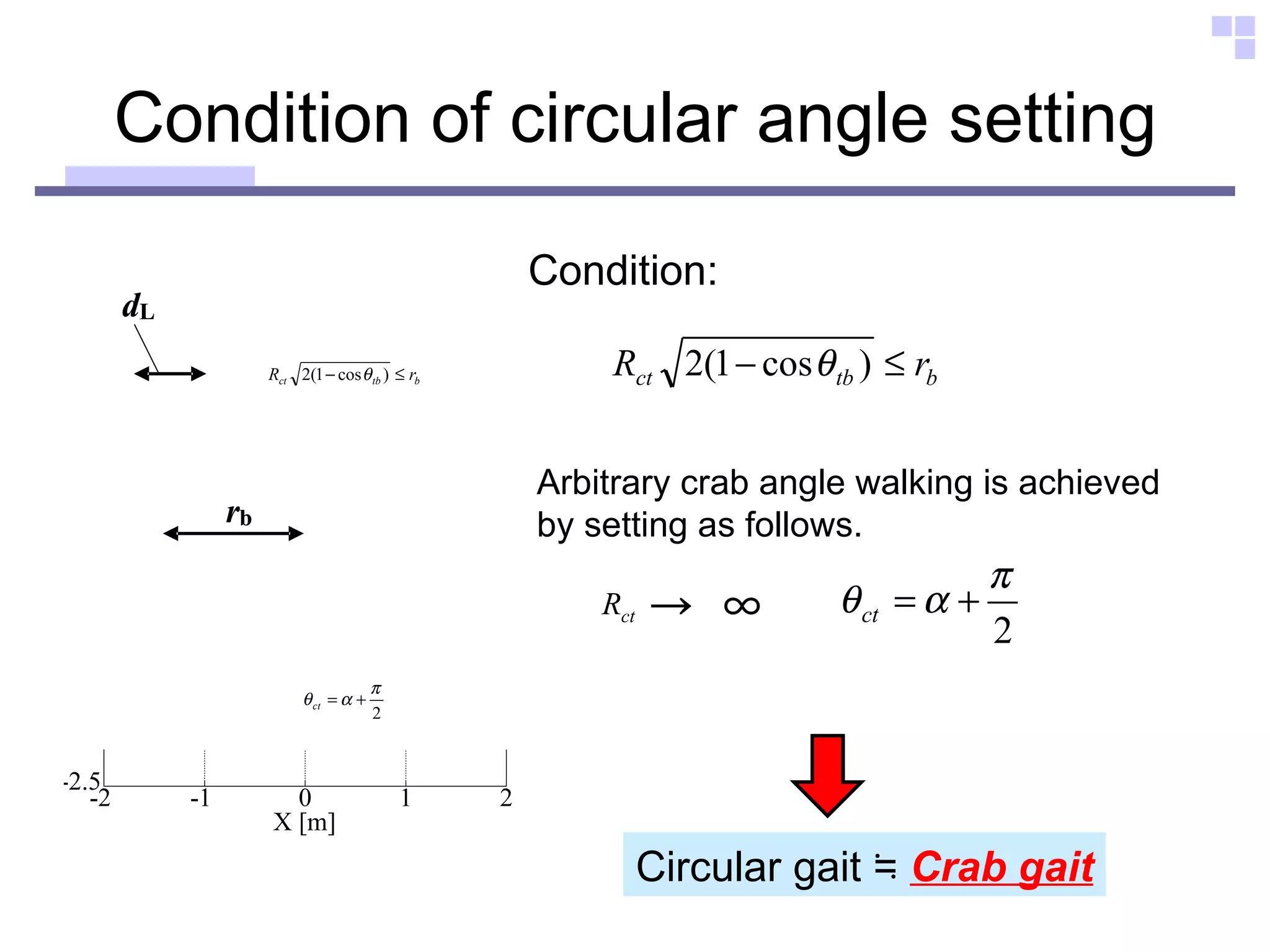
![Omni-directional gait Circular gait Rotation center Crab gait Crab gait Circular gait Circular gait includes all gait [*]](https://image.slidesharecdn.com/outline2-12730862668246-phpapp02/75/Outline-16-2048.jpg)
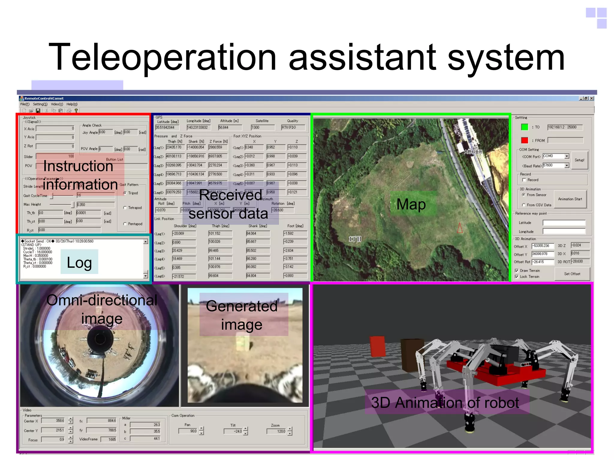
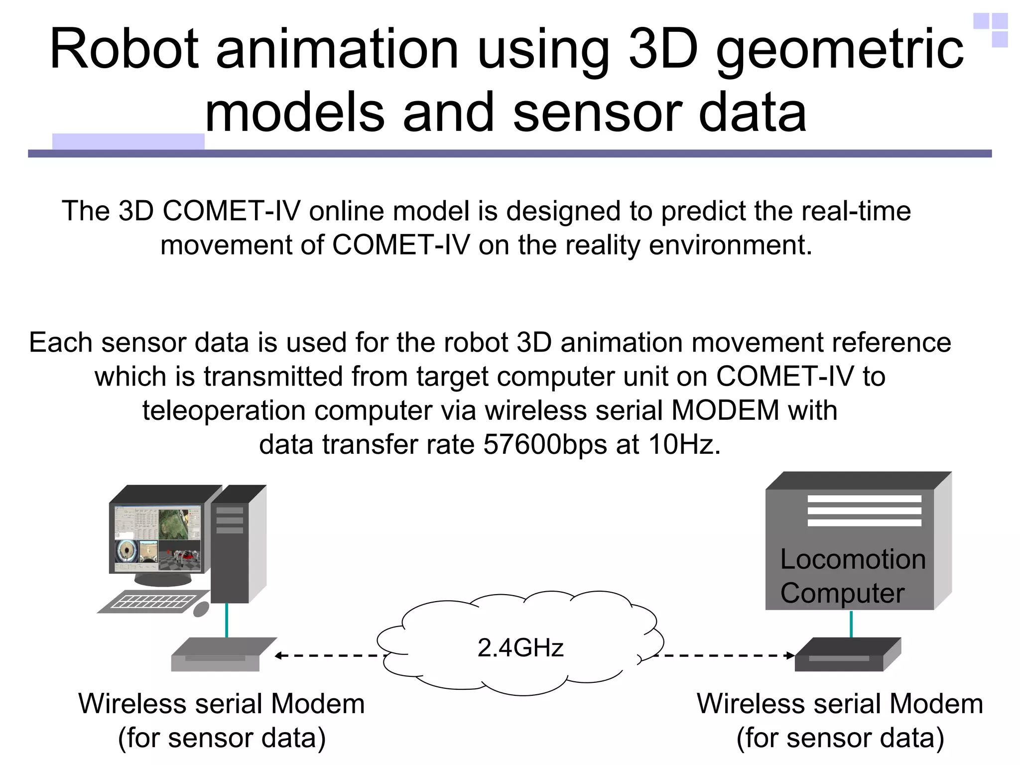
![Instruction information Action value shows the basic movement action. ■ Stand up ■ Sit down ■ Walking start ■ Walking stop Teleoperation Computer Locomotion Computer UDP Socket ( User Datagram Protocol ) Action Action value Cycle_Time Cycle time θ tb Traverse angle of the body center at one cycle [O t ] R ct Position of rotation center [polar display of O c ] θ ct](https://image.slidesharecdn.com/outline2-12730862668246-phpapp02/75/Outline-21-2048.jpg)
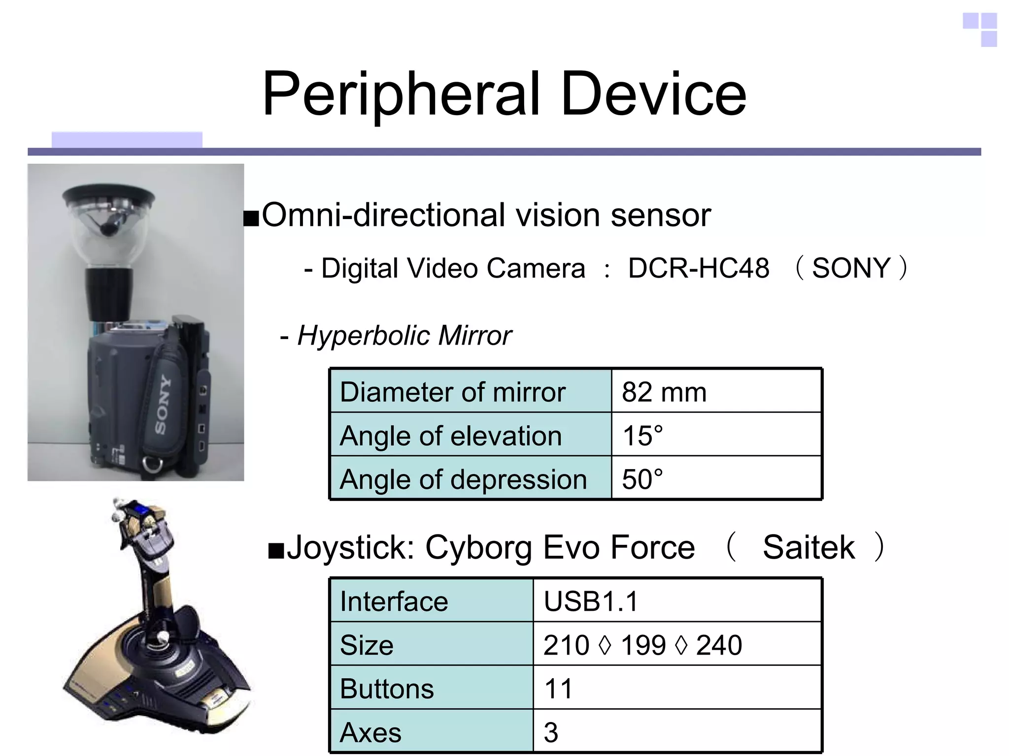
![Configuration of omni-directional vision sensor a 26.2 [mm] b 35.4 [mm] c 44.1 [mm] Diameter of mirror 55.0 [mm] Angle of elevation 15.0 [deg] Angle of depression 50.0 [deg]](https://image.slidesharecdn.com/outline2-12730862668246-phpapp02/75/Outline-24-2048.jpg)
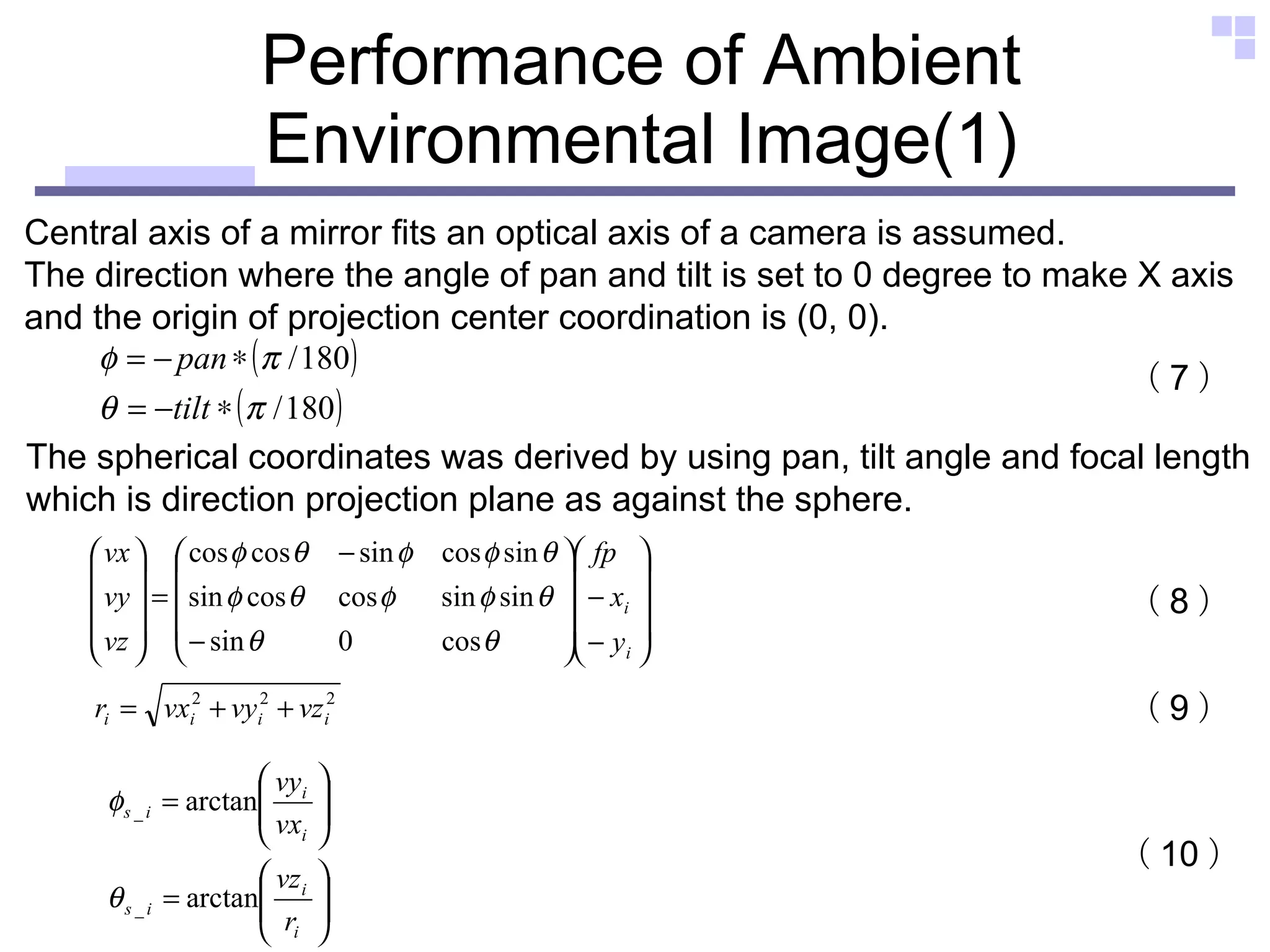
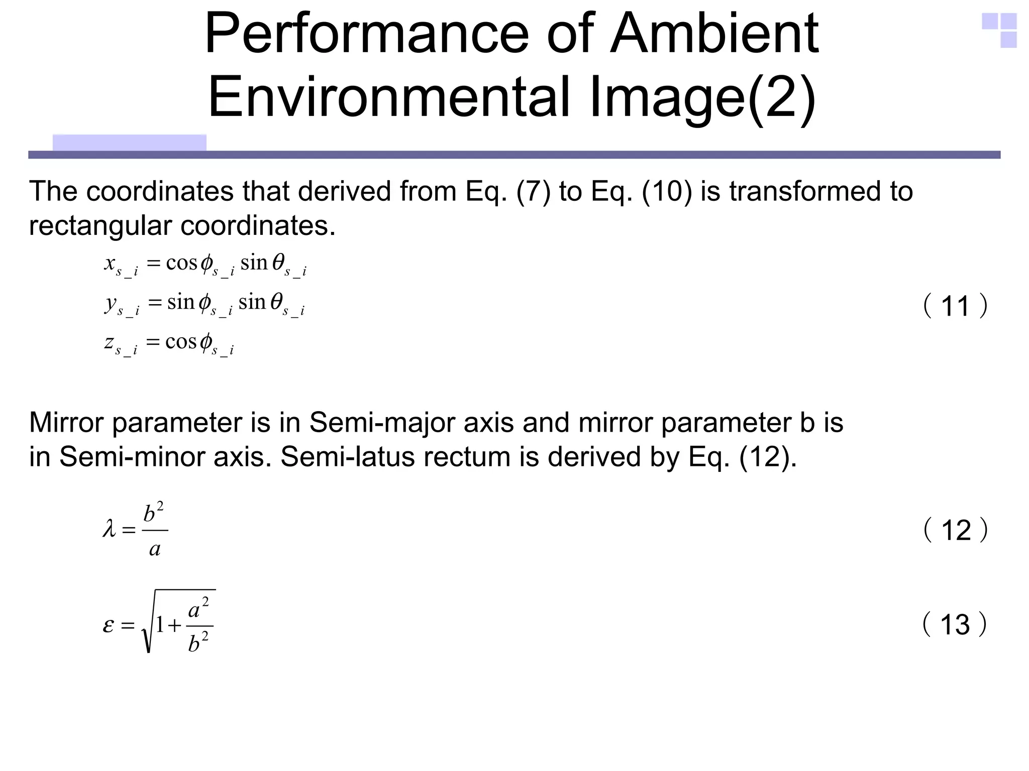
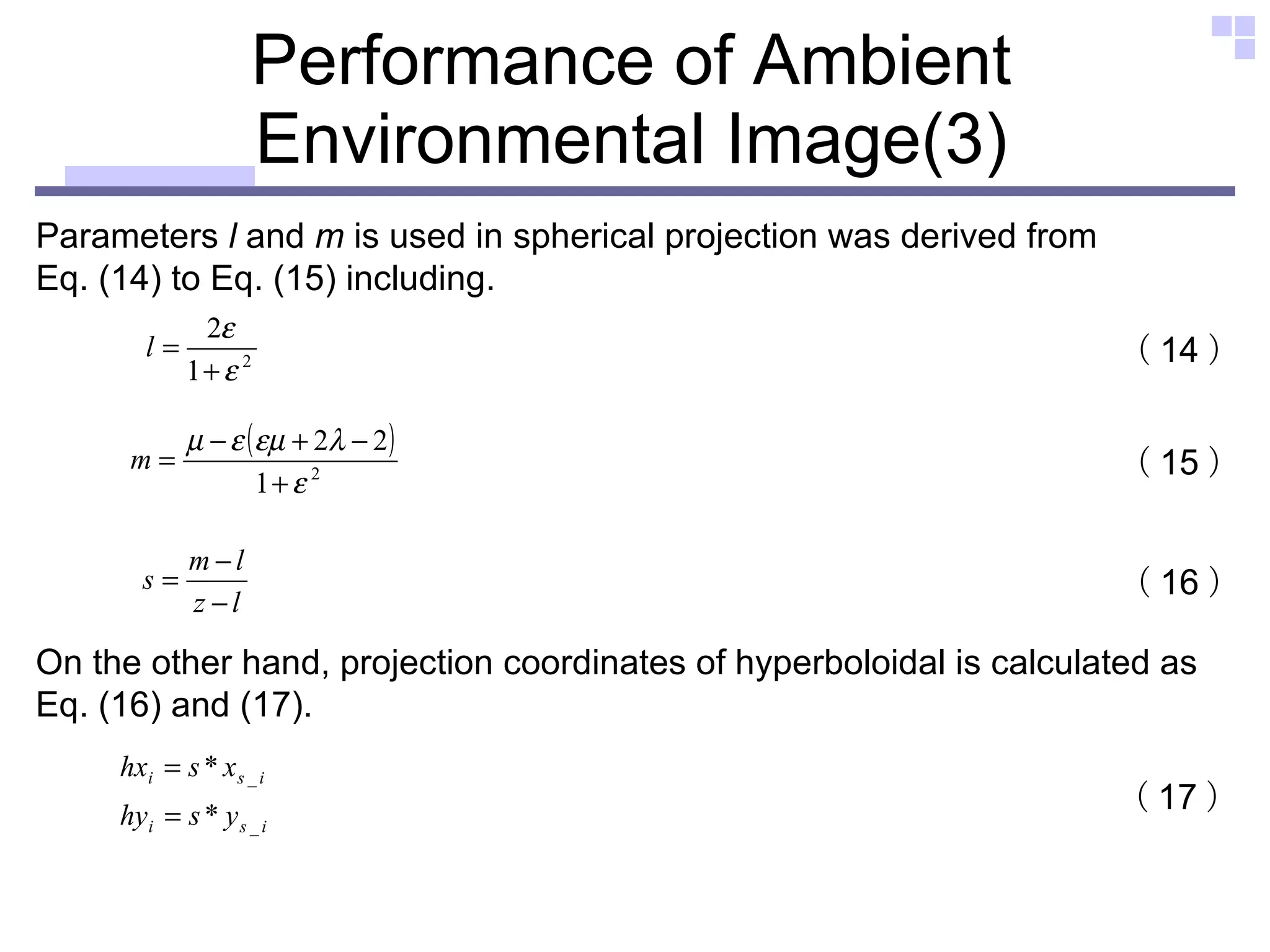
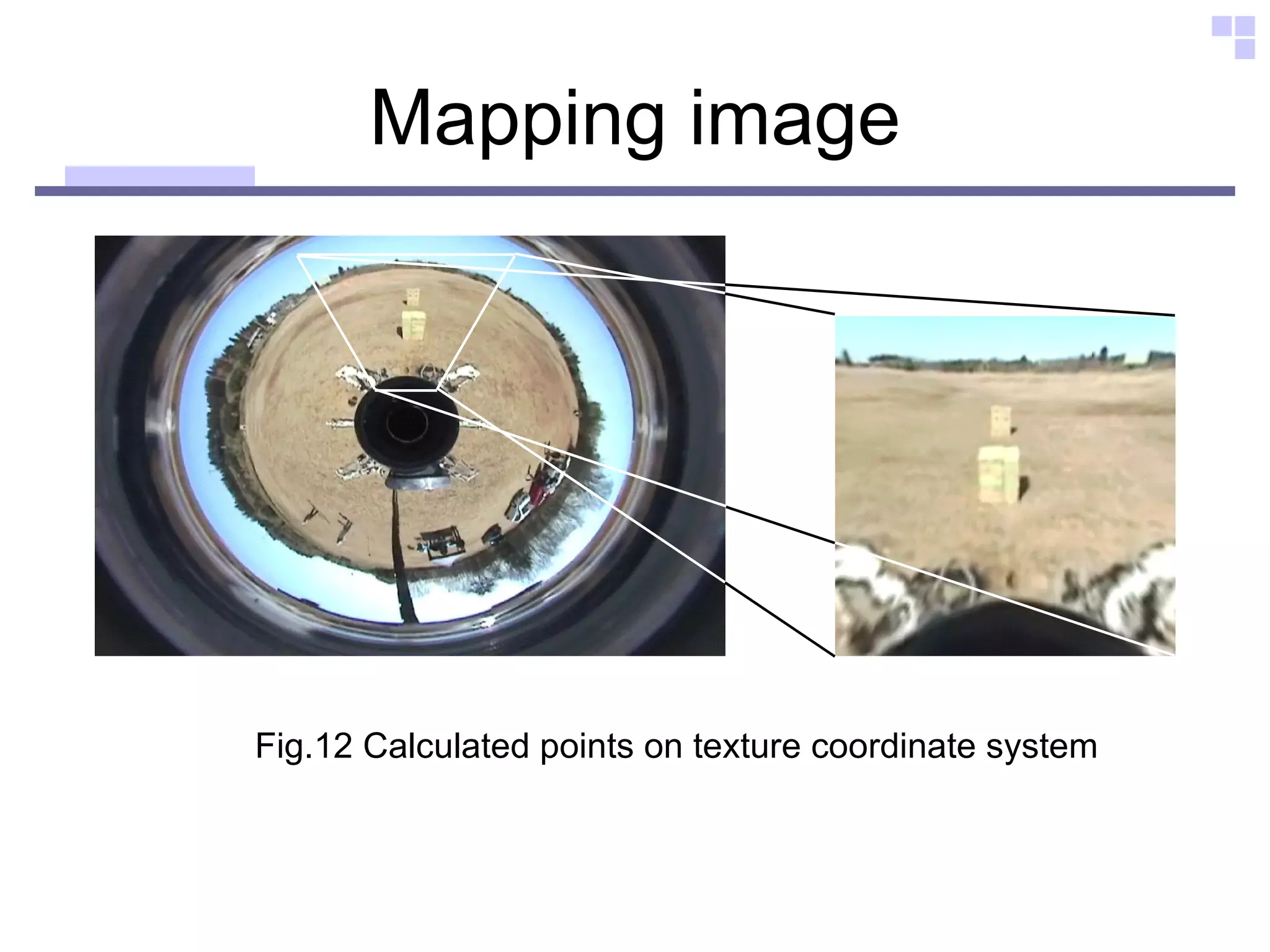
![Texture mapping Fig.11-(a) Fig.12 Fig.11-(b) The corresponding points in omni-directional image as against lattice points were derived from Eq1 to Eq3. ② ① Texture mapping vertex[0] = P[0] texcoor[0] = T[0] vertex[1] = P[1] texcoor[1] = T[1] vertex[2] = P[2] texcoor[2] = T[2] vertex[3] = P[3] texcoor[3] = T[3] ③](https://image.slidesharecdn.com/outline2-12730862668246-phpapp02/75/Outline-30-2048.jpg)
![The homogeneous transformation [1] Each leg (Foot - Shank - Thigh - Shoulder) After initialization, each part is expressed as follows. ( 20 ) ( 21 ) ( 22 ) ( 23 ) [2] Robot body ( 24 ) ( 25 )](https://image.slidesharecdn.com/outline2-12730862668246-phpapp02/75/Outline-35-2048.jpg)
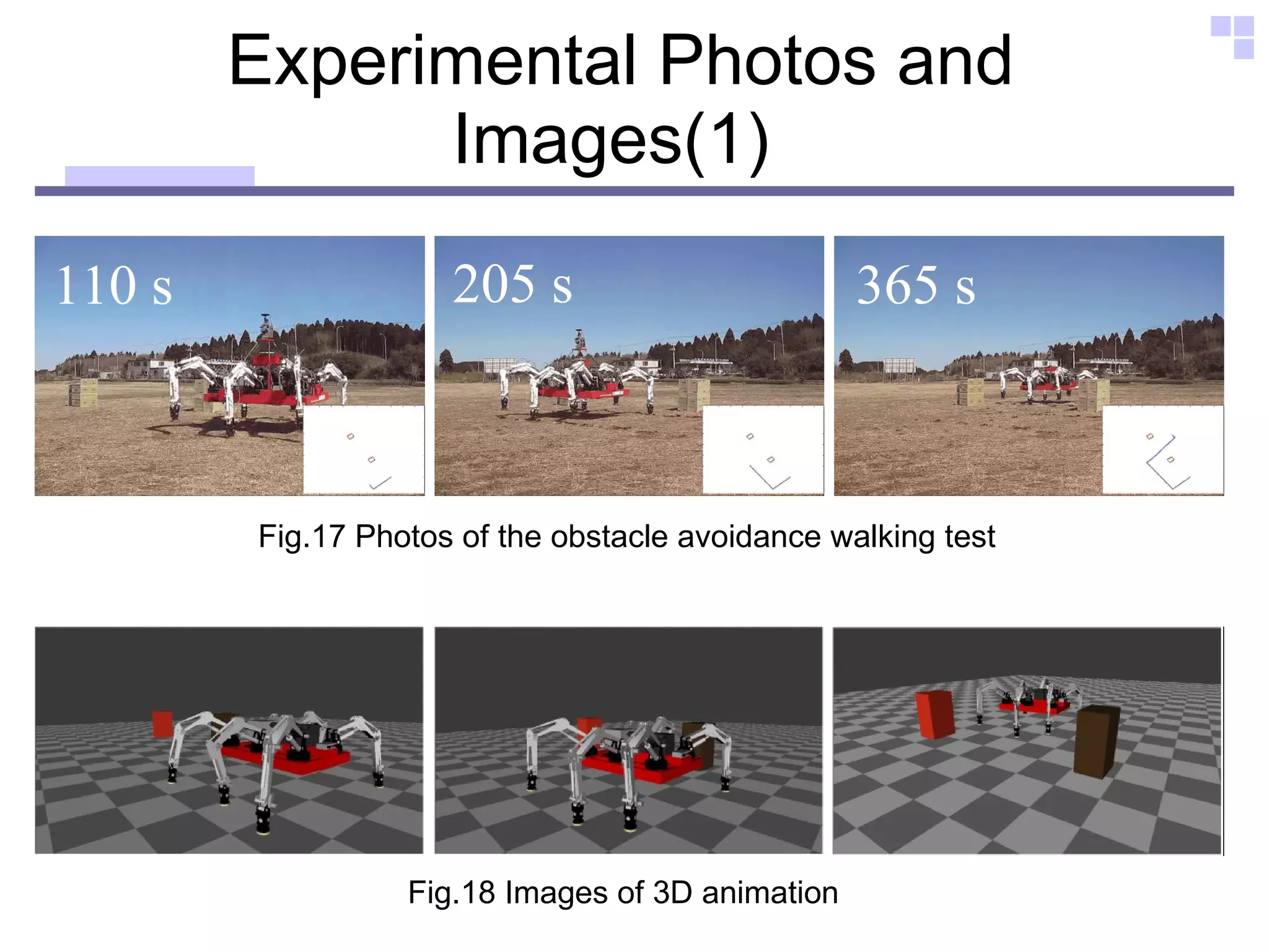
![Obstacle avoidance walking test Operator Goal Obstacle(2) Obstacle(1) ■ Controller is PID position control ■ Cycle time 16 [s] ■ Omni-directional gait ( crab gait ) ■ Tripod walking Robot Setting: ■ The number of lattices was set as 16×12 ■ virtual obstacle object on the screen System Setting:](https://image.slidesharecdn.com/outline2-12730862668246-phpapp02/75/Outline-36-2048.jpg)

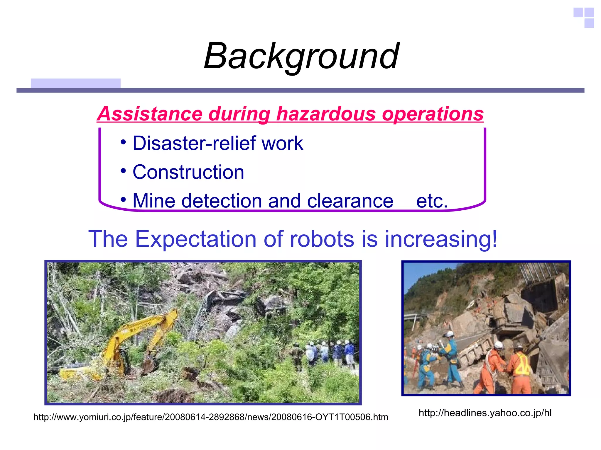
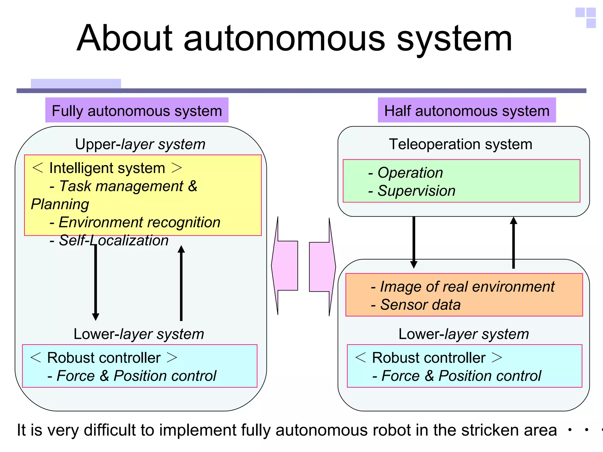
The document discusses the development of the Comet-IV robot, a hydraulically actuated hexapod designed for teleoperation in hazardous environments like disaster sites and rough terrains. It highlights advancements in omni-directional vision and 3D robot animation to facilitate control and navigation, alongside a teleoperation assistant system for managing robot movements. Future improvements are anticipated in network data transfer and self-localization for enhanced performance in difficult conditions.