Download to read offline

![1. Introduction (1)
Surgery robot [1] Walking Forest Machine [2]
Efficient assists and convenience for human life](https://image.slidesharecdn.com/dbbd3scztu28otbb8kr4-signature-5e8d2c37827bd56603d99b1f6f446b66a2ef9224453fa704beeaf40d5e4bc784-poli-150722184148-lva1-app6892/85/P1131131674-2-320.jpg)
![1. Introduction (2)
Efficient assists and convenience for human life
Cleaning robot, iRobot [3]
Service robot, PatrolBot [4]](https://image.slidesharecdn.com/dbbd3scztu28otbb8kr4-signature-5e8d2c37827bd56603d99b1f6f446b66a2ef9224453fa704beeaf40d5e4bc784-poli-150722184148-lva1-app6892/85/P1131131674-3-320.jpg)
![1. Introduction (3)
Ground robots
more statically stableLegged robot
Wheeled type robot [5]
Crawler type robot [5]
Legged type robot [4]](https://image.slidesharecdn.com/dbbd3scztu28otbb8kr4-signature-5e8d2c37827bd56603d99b1f6f446b66a2ef9224453fa704beeaf40d5e4bc784-poli-150722184148-lva1-app6892/85/P1131131674-4-320.jpg)


![2. COMET-IV Configuration (2)
Item Value
Overall Height [m] 2.80
Body Height [m] 0.8
Width [m] 3.50
Length [m]
(omni directional gait)
3. 0
Max. Walking Speed [m/h] 1000
Weight [kg] 2120
Gasoline Engine [cc] 750 (2 units)](https://image.slidesharecdn.com/dbbd3scztu28otbb8kr4-signature-5e8d2c37827bd56603d99b1f6f446b66a2ef9224453fa704beeaf40d5e4bc784-poli-150722184148-lva1-app6892/85/P1131131674-8-320.jpg)
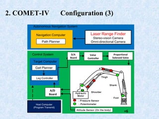
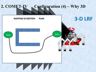

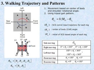


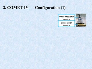
This document describes research on a hexapod robot called COMET-IV that uses a laser range finder (LRF) to assist with force-based walking. It discusses the robot's configuration including its dimensions, sensors, and control system. An algorithm is proposed that uses the LRF to build a 3D grid map of obstacles in the environment and dynamically adjusts the robot's stable walking range based on force feedback. Experiments show the vision-assisted approach provides more stable walking behavior compared to no vision input. Future work is planned to further integrate sensor data and control leg movements for varied terrain.