This document describes simulation and control of a biped walking robot using kinematic and dynamic modeling. It presents the dynamic equations of motion for a 2D model of the robot with 5 degrees of freedom. It then describes how impacts are modeled when the swing foot makes contact with the ground. A linear control method is developed using selected outputs to control the robot's motion along a straight line. Simulation results are shown for both 2D and 3D dynamic models of the robot, with angles, velocities, accelerations, and torques calculated. The robot is able to walk stably along a straight line by maintaining balance during single support phases, demonstrating the effectiveness of the control approach.
![Simulation and Control of a Biped Walking
Robot using Kinematic and Dynamic Modelling
M. Kojouri Manesh1a
, H. Kojouri Manesh2b
and A. Torabi3c
1
Dept. of Mechanical Engineering, Shiraz University, Shiraz, Iran
mohamadkojouri@yahoo.com
2
Dept. of Electrical Engineering, Islamic Azad University, Marvdasht, Iran
kojourihamid@yahoo.com
3
Dept. of Industrial Engineering, Islamic Azad University, Shiraz, Iran
torabi_amir251@yahoo.com
Abstract— In this article, we intend to consider the
behavior and control of a biped walking robot using
kinematic and dynamic relations. At first, by using simple
model of humanoid robot and essentional equations the
angles, angular velocities, accelerations of motors and
required torques for moving on a straight line are find out. In
the second step considering numerical values of the robot
parameters and constructing the dynamic model the abilities
of robot are examined and simulated.
Keywords—Humanoid robot; simulation; control
I. INTRODUCTION
The need for robots has recently been changed from
industrial automation to human friendly robot system [1].
One of them is WABIAN constructed by Waseda
University and WABOT which is the world’s first life-
sized humanoid robot with the ability of walking and
dancing [2]. H6 and H7 are humanoid robots constructed
by University of Tokyo [3]. JOHNNIE is an
anthropomorphic autonomous biped robot constructed by
Technical University of Munich [4]. MK.5 is a compact
size humanoid robot with 24 D.O.F. constructed by Aoyma
Gakuin University [5]. The most impressive humanoid
robot should be HONDA humanoid robots. P2 is the
world’s first cable-less humanoid robot, which can walk
and can go up/down stairs [6]. P3( height 1600 mm, width
600 mm, weight including batteries 130 kg, 6 D.O.F./Leg,
7 D.O.F./Arm, 1 D.O.F./Hand) appeared in 1997 with the
same mobility as P2 [7]. In 2000, further downsizing P3,
ASIMO that stands for Advanced Step in Innovative
Mobility appeared with children-size (height 1200 mm,
width 450 mm, weight including batteries 43 kg, 6
D.O.F./Leg, 5 D.O.F./Arm, 1 D.O.F./Hand, 2 D.O.F./Head)
[8,9].
This work includes the simple model of ASIMO robot
and simulates its motion using series of motors to establish
automatically robot stability during its motion. This robot
has 23 D.O.F. Six motors that move the robot on the
straight direction, eight motors control robot's stability and
the other motors are used for extra body movements and
3D motion.
II. EQUATIONS OF MOTION
A. Two dimensions dynamic equation
There are many and complex equations to control a
biped walking robot accurately; therefore, it is difficult to
achieve a standard control algorithm. So, the simple models
are used. A simple 2D model which has 5 D.O.F is shown
in Fig. 1 [10].
Fig. 1 absolute angels of 2D model with 5 D.O.F.
The dynamic model is given by:
AqgqqcqqB )(),()( (1)
Where )(qB is the inertia matrix, ),( qqc groups the
coriolis and centrifugal terms, and )(qg represents the
gravitational term. The vector represents only the torques
on the actuated motors, and matrix A is the mapping from
the relative torques to the absolute torques. When only one](https://image.slidesharecdn.com/19-151003070317-lva1-app6891/75/simuliton-of-biped-walkinng-robot-using-kinematics-1-2048.jpg)
![foot is in contact with the ground, the system is said to be
single support phase and when both feet are in contact with
the ground is double support phase. Note that in this
situation there is a closed kinematic chain formed by the
two legs and the ground. The total number of degrees of
freedom in this phase is three.
B. Impact model
The transition from the single support phase to the
double support phase is assumed to occur with an anelastic
collision of swing leg. This event results in a discontinuity
of the joint velocities described by this equation [11].
),(
qqq (2)
Where the superscript (+
) indicates a value immediately
after and (
) immediately before the impact. The starting
point is the extended dynamic model of the system that also
includes the position and velocity of the stand foot. The
new model has then 7 degree of freedom and can be
represented as:
(3)
Where T
ppn yxqqx ),,,...,( 1 is a new state vector that
includes the Cartesian coordinate’s xp and yp of the stand
foot. On the right hand side there are the joint torques T
and the constant forces ),,,( 00
n
c
t
c
nt
FFFFF are the
forces exerted by the ground on the robot. The key idea is
now to integrate the motion. With this integration, all
forces that are not impulsive can be eliminated. Suppose
that the stand foot gets fix on the ground and to be lifted
after finishing impulse, by using collision theory, the
velocity will be obtained after contacting the foot.
(4)
That β is the integrated impulsive force.
C. Robotic linear control equation
By using four suitable outputs which are shown in Fig.
2 and z5 which is moving of body on the x axis, we have
[11]:
(5)
Fig. 2 Taken outputs from robot.
These values should be obtained by using absolute
angles as follow:
22115
443322114
443322113
52
22111
slslXy
clclclcly
slslslsly
qy
clcly
hip
(6)
In this Equations il is length of each parts and
)sin(,)cos( iiii qsqc . If we derivate from above
Equations to t will have:
),()( qqnqqJy (7)
The q state should be obtained from dynamic model:
)](),([)(1
qgqqcAqBq
(8)
The simpler form of Eq. 7 with substituting the above
Equations is:
),(~)(
~
qqnqJy (9)
By applying this linear algorithm we express a new
dynamic system:
),,(55
444
333
222
111
zzyz
yz
yz
yz
yz
(10)
To obtain a linear system with static feedback position,
we specify the torques value like this:
)),(~()(
~ 1
qqnqJ
(11)
F
qD
xD
T
xgxxcxxB
)(
)(
0
0)(),(ˆ)(
2
1
2
11
^
)(
D
D
xBxx
),,(5
44
33
22
11
qqz
yz
yz
yz
yz
](https://image.slidesharecdn.com/19-151003070317-lva1-app6891/75/simuliton-of-biped-walkinng-robot-using-kinematics-2-2048.jpg)
![By choosing , this dynamic system will be stable
and iy will reach to the designed value to move on straight
direction.
D. Motional constraint for controlling
The main duty of robot controller is ability to adjust
robot’s motion and speed. In this article, the time of swing
foot trajectory is used for controlling walking and velocity.
The velocity of walking is controlled by using of end in
time of the swing foot trajectory or by ending phase of joint
leg on the x axis direction. Therefore, an approximate
simple dynamic system is assumed which is including
inverted pendulum with variant length and concentrated
mass in one point, as shown in Fig. 3 [12]. The pendulum
mass (m) shows the total mass of the robot.
Fig. 3: Scheme of robot with assuming of concentrating mass and
variant length.
If the most robot mass to be concentrated in the middle
of the body, we can assume that the approximated mass of
the inverted pendulum has always constant height. To
keep 1y constantly, the concentrated mass is desired to move
on a parallel line with x axis. So we can do this by a linear
motor and a control system. The motion of mass m, in x
axis, is given as follows:
Txm (12)
Where T is the horizontal component of F that is shown
in Fig. 3 we conclude:
0
2
,0
y
g
xx (13)
Where:
2
2
)(
00
2
00
1
21
xx
C
xx
C
eCeCtx tt
(14)
00 xx is the lowest initial speed that the mass
should possess to reach to the point 0x so for continuing
the motion on the x axis, the initial speed should be more
than this value.
E. Swing foot rejection of robot
We approximate the swing foot trajectory by a cubic
function including 2 functions on the y axis and one
function for motion on the x axis that is shown in Fig. 4
and Eq. 15 [10].
Fig. 4: Swing foot trajectory.
]1,()(
),0[)(
)(
22
2
2
3
22
11
2
1
3
11
23
csdscsbsasy
csdscsbsasy
dscsbsasx
yyyysf
yyyysf
xxxxsf
(15)
By using the boundary condition in single support phase
these 3 functions are derived. Using robot dimensions, we
can obtain the torque values in each motor. Thereafter with
Eq. 11 and by applying obtained torques to the motors,
robot moves on the defined direction.
III. NUMERICAL EXAMPLE
With considerate 2D robot model as shown in Fig. 5
and given dimensions and size in Eq. 16 we want to
calculate the rotating angle values, angular accelerations,
angular velocities and torques of each motor.
Fig. 5: Length and mass of each part in 2D model.](https://image.slidesharecdn.com/19-151003070317-lva1-app6891/75/simuliton-of-biped-walkinng-robot-using-kinematics-3-2048.jpg)
![For doing this it needs to calculate the swing foot
trajectory and body trajectory in single support phase
which is used plastic contact assumption. A prepared
program in Matlab-Simulink gives the trajectory of swing
foot. The result is depicted in Fig.6. The numerical value of
parameters are as follows:.
Fig. 6: The x-y diagram of swing foot trajectory in single support
phase.
.67.26;lc5.16;lc4.16;lc3.26;lc2lc1
.32.06;I5.04;I4.04;I3.06;I2I1
.67.41;l5.34;l4.34;l3.41;l2l1
94;m54.6;m44.6;m34;m2m1
(16)
IV. OBTAINED SIMULATION
To evaluate results of motion on the straight direction
the robot of Fig. 7 is considered and its motion is simulated
[13,14].
Fig. 7: Simulating 3D model of robot in the SOLID WORKS
software.
The illustrated 3D model has 23 DOF which is as
follows: 6 D.O.F in each leg, 4 D.O.F in each hand, 2
D.O.F in head, 1 D.O.F in waist.
Fig. 8: The rate of rotating of robot's upper body in 3 directions of
coordinate axis's.
To control the robot, joint angles of the upper body in 3
directions is obtained from motion simulation by using
control systems in MATLAB software and also using
feedback from the angles. The results are shown in Fig. 8.
Simulation of the robot motion on the straight direction
is shown in Fig. 9 by MSC. Visual Nastran software and
rotating angles, angular velocities and angular accelerations
in simulating of motion of this robot are shown in Fig. 10:
Fig. 9: Simulation of robot motion on the straight direction.](https://image.slidesharecdn.com/19-151003070317-lva1-app6891/75/simuliton-of-biped-walkinng-robot-using-kinematics-4-2048.jpg)
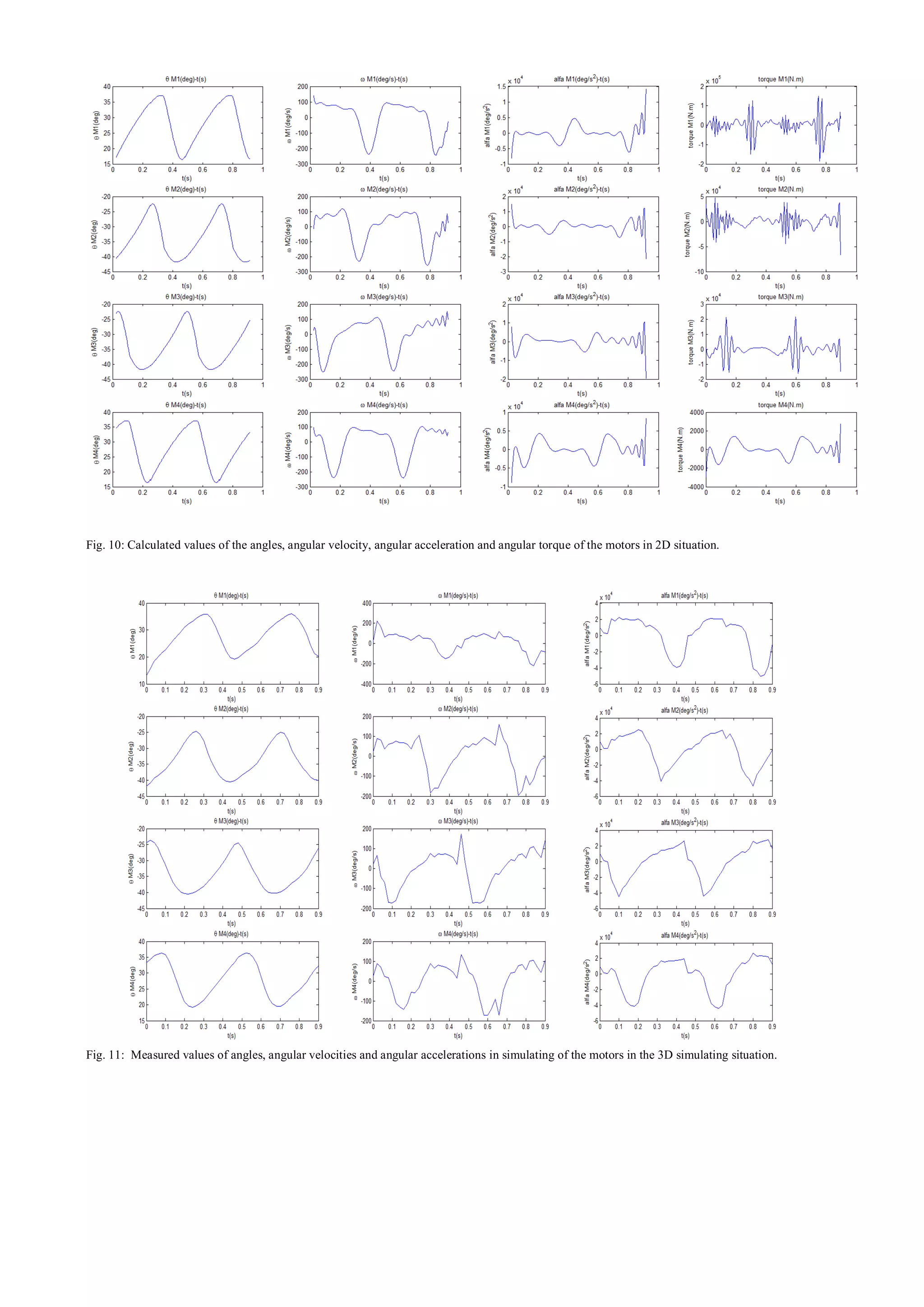
![V. CONCLUSION
Considering figures 10 and 11 the following results can be
obtained:
The angular motion motors in 2D and 3D simulation are
the same. During the contact time in simulation process there
is jump discontinuity and jerk in angular acceleration of
revolute joints which is due to the impulse between the ground
and robot foot. Therefore the angular acceleration also takes
variants to the 2D situation. The calculated torqueses are not
comparable to each other because of different natures in 2D
and 3D situations. Controlling the robot is done very well;
during it moves on the straight direction in x-y plane and right
on z direction. This matter is occurred because of keeping
stability of the robot in single support leg of course as it is
shown in Fig. 8 effect of the robot control as well as the
movements of hands and feedback of upper part of the robot,
the value of this revolute joint angles with respect to time can
be investigated.
REFERENCES
[1] K. Yokoyama, J. Maeda, T. Isozumi, and K. Kaneko, ―Application of
Humanoid Robots for Cooperative Tasks in the Outdoors,‖ Proc.
Int. Conference on Intelligent Robots and Systems, 2001.
[2] J. Yamaguchi, E. Soga, S. Inoue, and A. Takanishi, ―Development of
a Bipedal Humanoid Robot – Control Method of Whole Body
Cooperative Dynamic Biped Walking,‖ Proc. IEEE Int.
Conference on Robotics and Automation, pp. 368-374, 1999.
[3] K. Nishiwaki, T. Sugihara, S. Kagami, F. Kanehiro, M. Inaba, and H.
Inoue, ―Design and Development of Research Platform for
Perception-Action Integration in Humanoid Robot: H6,‖ Proc. Int.
Conference on Intelligent Robots and System, pp.1559-1564, 2000.
[4] M. Gienger, K. Löffler, and F. Pfeiffer, ―Towards the Design of
Biped Jogging Robot,‖ Proc. IEEE Int. Conference on Robotics
and Automation, pp. 4140-4145, 2001.
[5] T. Furuta, Y. Okomura, and K. Tomiyama, ―Design and Construction
of a Series of Compact Humanoid Robots and Development of
Biped Walk Control Strategies,‖ Proc. IEEE-RAS Int. Conference
on Humanoid Robots, 2000.
[6] K. Hirai, ―Current and Future Perspective of Honda Humanoid
Robot,‖ Proc. IEEE/RSJ Int. Conference on Intelligent Robots and
Systems, pp. 500-508, 1997.
[7] K. Hirai, M. Hirose, Y. Haikawa, and T. Takenaka, ―The
Development of Honda Humanoid Robot,‖ Proc. IEEE Int.
Conference on Robotics and Automation, pp. 1321-1326, 1998.
[8] M. Hirose, Y. Haikawa, T. Takenaka, and K. Hirai, ―Development of
Humanoid Robot ASIMO,‖ Proc. Int. Conference on Intelligent
Robots and Systems, 2001.
[9] K. Yokoi, M. Kobayashi, H. Hasunuma, H. Moriyama, T. Itoko, Y.
Yanagihara, T. Ueno, and K. Ohya, ―Application of Humanoid
Robots for Teleoperations of Construction Machines,‖ Intelligent
Systems Institute, AIST, Tsukuba, Ibarak , 2002.
[10] F. Zonfrilli, G. Oriolo, D. Nardi, ―A Biped Locomotion Strategy for
the Quadruped Robot Sony ERS-210,‖ 2001.
[11] F.Zonfrilli, ―Theoretical and Experimental Issues in BipedWalking
Control Based on Passive Dynamics,‖ Ph.D. Thesis in Systems
Engineering, 2004.
[12] H. Miura and I. Shimoyama, ―Dynamic walk of a biped,‖ The Int.
Journal of Robotics Research 3, 1984.
[13] K. Kaneko, F. Kanehiro, Sh. Kajita, K. Yokoyama, K. Akachi, T.
Kawasaki, Sh. Ota and T. Isozumi, ―Design of Prototype Humanoid
Robotics Platform for HRP,‖ Proceedings of the 2002 IEEE/RSJ
Intl. Conference on Intelligent Robots and Systems, 2002.
[14] K. Kaneko, F. Kanehiro, Sh. Kajita, H. Hirukawa, T. Kawasaki, M.
Hirata, K. Akachi and T. Isozumi, ―Humanoid Robot HRP-2,‖
Proceedings of the 2004 IEEE International Conference on
Robotics & Automation, New Orleans, 2004.](https://image.slidesharecdn.com/19-151003070317-lva1-app6891/75/simuliton-of-biped-walkinng-robot-using-kinematics-6-2048.jpg)


