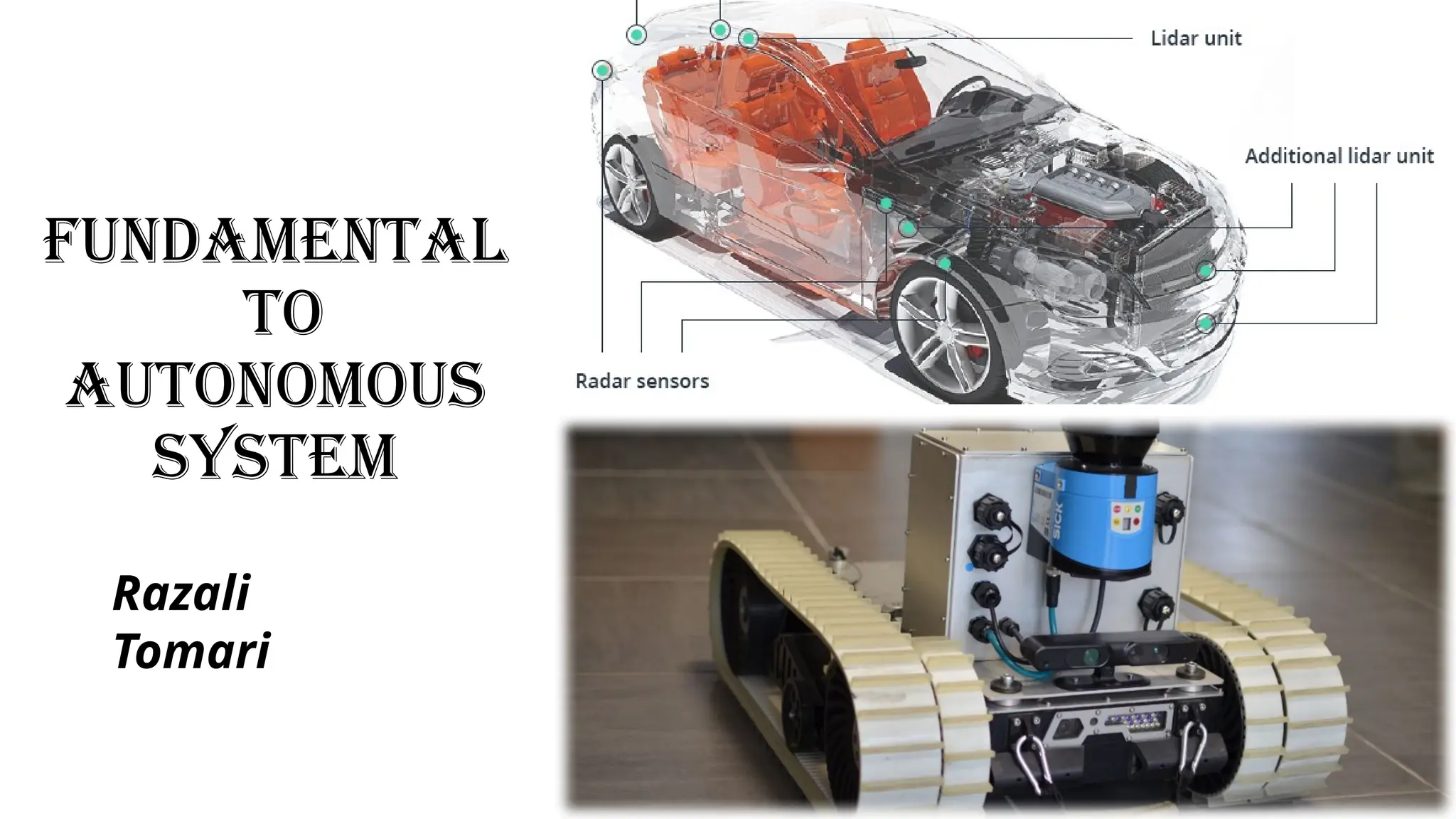
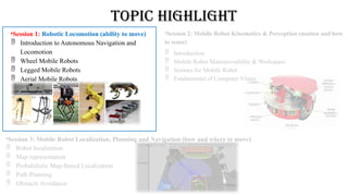
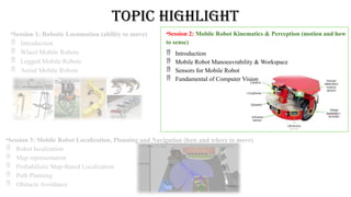
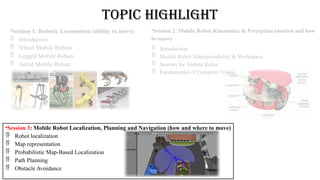
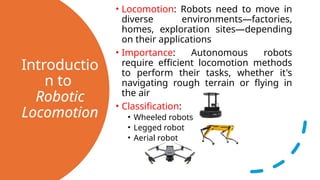
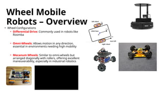
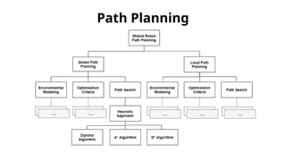
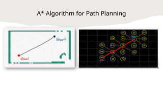
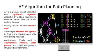
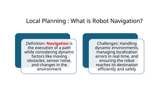
FUNDAMENTAL
TO
AUTONOMOUS
SYSTEM
Razali
Tomari
Topic Highlight
•Session 1: Robotic Locomotion (ability to move)
 Introduction to Autonomous Navigation and
Locomotion
 Wheel Mobile Robots
 Legged Mobile Robots
 Aerial Mobile Robots
•Session 2: Mobile Robot Kinematics & Perception (motion and how
to sense)
 Introduction
 Mobile Robot Manoeuvrability & Workspace
 Sensors for Mobile Robot
 Fundamental of Computer Vision
•Session 3: Mobile Robot Localization, Planning and Navigation (how and where to move)
 Robot localization
 Map representation
 Probabilistic Map-Based Localization
 Path Planning
 Obstacle Avoidance
Topic Highlight
•Session 1: Robotic Locomotion (ability to move)
 Introduction
 Wheel Mobile Robots
 Legged Mobile Robots
 Aerial Mobile Robots
•Session 2: Mobile Robot Kinematics & Perception (motion and how
to sense)
 Introduction
 Mobile Robot Manoeuvrability & Workspace
 Sensors for Mobile Robot
 Fundamental of Computer Vision
•Session 3: Mobile Robot Localization, Planning and Navigation (how and where to move)
 Robot localization
 Map representation
 Probabilistic Map-Based Localization
 Path Planning
 Obstacle Avoidance
Autonomous navigation system
Navigation is the ability to determine your location
within an environment and to be able to figure out
a path that will take you from your current location
to some goal.
Autonomous, it's how we get a vehicle to determine
its location using a set of sensors and then to move
on its own through an environment
to reach a desired goal.
Requirement for Autonomous navigation system
MAP SENSORS & ACTUATOR
PATH PLANNING & NAVIGATION ALGORITHM
Introductio
n to
Robotic
Locomotion
• Locomotion: Robots need to move in
diverse environments—factories,
homes, exploration sites—depending
on their applications
• Importance: Autonomous robots
require efficient locomotion methods
to perform their tasks, whether it's
navigating rough terrain or flying in
the air
• Classification:
• Wheeled robots
• Legged robot
• Aerial robot
Wheel Mobile
Robots – Overview
• Wheel Configurations
• Differential Drive: Commonly used in robots like
Roomba
• Omni-Wheels: Allows motion in any direction,
essential in environments needing high mobility
• Mecanum Wheels: Similar to omni-wheels but
arranged diagonally with rollers, offering excellent
maneuverability, especially in industrial robotics
Advantage
s
• Stability: Wheeled robots are
inherently stable compared to
legged robots which require
balance mechanisms
• Energy Efficiency: On flat
surfaces, wheeled robots
consume less energy, making
them a better choice for long-
range travel
• Simple Control: Compared to
legged or aerial robots, wheeled
robots are easier to control since
their motion is mostly linear
Challenges
• Terrain Limitations: Wheeled
robots struggle on rough or
uneven terrain and cannot
climb stairs
• Skidding/Slipping: On certain
surfaces , wheels lose traction,
making control less precise
• Maneuverability: Non-
holonomic wheeled robots
can't move sideways, limiting
their ability to maneuver in
constrained spaces
Wheel Mobile Robots
Legged Mobile
Robots – Overview
• Legged Systems
• Bipedal (2 legs): Humanoid robots like
Boston Dynamics’ Atlas and ASIMO.
• Quadrupedal (4 legs): Robots like
Spot offer a balance between stability
and mobility, making them excellent
for rough, uneven terrains
• Hexapods/Octopods: More legs
increase stability, with applications in
rough terrain exploration
• Terrain Adaptability: Unlike wheeled
robots, legged robots excel on rough
and uneven surfaces, making them ideal
for search and rescue operations or
Mars exploration
• Obstacle Navigation: Legs allow robots
to step over obstacles, a capability not
possible with wheels
• Improved Maneuverability: Legged
robots can rotate in place and move in
complex ways, making them more
versatile in confined environments
• Control Complexity: Balancing a bipedal
robot, especially on rough terrain, is
computationally intensive and requires
advanced control algorithms
• Energy Consumption: Legged
locomotion requires significantly more
energy compared to wheels
• Stability Issues: Slipping or losing
balance is more common in legged
robots, especially on inclines or slippery
surfaces
Legged Mobile
Robots
Advantage
s
Challenges
Aerial Mobile Robots – Overview
• Types
• Rotary-Wing: Common quadcopters like DJI drones
• Fixed-Wing: More like airplanes; they require a
runway or catapult to launch
• Hybrid Systems: Combines aspects of rotary and
fixed-wing designs, offering VTOL capabilities,
useful for high-endurance tasks
• Coverage of Large Areas: Aerial
robots can traverse large areas
quickly, making them ideal for
surveillance, mapping, or delivery
• No Terrain Restrictions: Unlike
ground robots, aerial systems can
navigate over challenging landscapes
such as mountains, lakes, and dense
forests
• Speed: Aerial robots, especially fixed-
wing drones, can move faster than
ground robots, useful in time-sensitive
tasks like emergency response
• Battery Life: Most consumer drones have
limited flight times
• Payload Restrictions: Aerial robots have
limited capacity to carry heavy payloads,
which constrains their use in applications
like heavy cargo transport
• Safety & Regulations: Navigating airspace,
avoiding collisions, and abiding by
government regulations is challenging,
especially in urban environments
Aerial Mobile Robots
Advantage
s
Challenges
Comparison of Locomotion Modes
•A comparison chart of the key metrics
•Efficiency: Wheeled > Aerial > Legged
•Terrain Adaptability: Legged > Aerial >
Wheeled
•Complexity: Legged > Aerial > Wheeled
Future Trends in Robotic
Locomotion
• Soft Robotics: Soft robots with flexible
limbs and surfaces adapt better to
unpredictable environments, such as those
found in medical surgery or underwater
exploration
• Hybrid Locomotion: Systems combining
wheels, legs, and even flight capabilities
for all-terrain versatility
• Autonomy & AI: Robots are increasingly
using AI to make decisions about which
mode of locomotion to use in specific
environments
Introduction to Mobile Robot
Kinematics
• Kinematics: Deals with motion without considering
forces, which is critical for understanding how a robot’s
joints, wheels, or actuators result in motion
• Robot Motion: The ability to predict how a robot will
move given input commands is the foundation of path
planning and control
• DoF: Degrees of Freedom represent the robot
capability to move in certain directions (Mobile robot,
3DOF (x,y,θ)
• Holonomic Systems: Can achieve any movement
instantaneously in all directions (omni wheel)
• Non-Holonomic Systems: Subject to motion
constraints (differential drive)
Kinematic
Models for
Wheeled Robots
• Differential Drive: The simplest
wheeled robot model where each
wheel operates independently
• Car-like: Simplified model for
cars and motorcycles
Sensors for Mobile Robots
• Sensors: Critical for perception, allowing robots to understand
their surroundings and make decisions based on that data
• Main Categories
• Internal Sensors: Measure internal robot states like wheel
speed, battery levels
• External Sensors: Measure the external environment, such as
proximity to obstacles or temperature
2D LIDAR 3D LIDAR
RADAR 3D CAMERA
ENCODER
IMU
Internal Sensors
• Examples
• Wheel Encoders: Measure
the rotation of wheels, used
for odometry
• Inertial Measurement Unit
: Tracks acceleration and
orientation, essential for
stabilizing aerial robots and
aiding localization in all
mobile robots
External Sensors – Vision Sensors
• Cameras: Allow robots to perceive the
environment visually, enabling object
recognition and tracking
• Challenges: Cameras are subject to issues
like poor lighting or occlusions, but they
are versatile and rich in information
• Applications: Used in object detection ,
SLAM , and navigation
External Sensors – Range Sensors
• LiDAR: A laser-based sensor used to measure
distances to objects with high accuracy,
generating 3D point clouds of the environment
• Ultrasonic Sensors: Emit sound waves and
measure the time it takes for the echoes to
return
• Infrared Sensors: Emit infrared light to detect
obstacles; typically used for short-range
distance measurement
External Sensors – Contact Sensors
• Touch Sensors: Register contact
with objects, useful for close-
proximity tasks or when precision is
needed
• Bump Sensors: Detect when a robot
physically bumps into an object;
commonly used in early-stage
robots for basic collision detection
Sensor Fusion and
Challenge
• Definition: Combines data from multiple sensors to improve
accuracy and robustness
• Applications: Used in self-driving cars, where a combination of
LiDAR, cameras, and radar ensures the vehicle can navigate
safely in complex environments
• Sensor Noise: All sensors are subject to noise—random
inaccuracies that affect the sensor data
• Environmental Factors: Issues like low lighting, rain, snow, or
fog can severely impact the performance of vision-based
sensors
Case Study: Autonomous Wheelchair
System • Sensors Used
• LiDAR: For precise, real-
time mapping and obstacle
detection
• 3D Cameras: For human
face estimation and
obstacle detection
• IMU: determine wheelchair
orientation
• Camera : User intent
prediction
( Threat and Human detection )
( Orientation refinement)
( Obstacle Detection)
( User Intent Prediction)
Laser FOV
Kinect FOV
Method Pipeline
Kinect
Laser
Pose Tracking
Blob
Mapping
Head
Detection
Region
Validation
Blob
Analysis
Personal
Space
User
αu
-ve
Positive & Overhanging Obstacles Negative Obstacles
Motor Command
Human detection & pose tracking
Navigation Map
User Input
25
Socially
Acceptabl
e
Safety
HCI
Interface
26
• Obstacles Definition (Murarka A, 2010):
Ground plane
Overhanging Obstacle
Positive Obstacle
Negative Obstacle
27
αgX + βgY + γgZ +d =0
• Initial step for detecting the obstacle
P1
P0
αgX + βgY + γgZ +d =0
Pc
Ground plane Ground plane equation :
Point Cloud, e.g. Pc, location w.r.t
ground plane:
2
2
2
g
g
g
c
g
c
g
c
g d
Z
Y
X
s












Obstacle
Negative
Obstacle
Positive
ve
ve
s






s
28
• Negative Obstacle Detection using the S sign
Problem :N
ot
Correctly
Detected
P1
P0
Pc0
Virtual
ground
plane
Pc
Ground
plane
c
c
g
c
g
c
g
co P
Z
Y
X
d
P















• Solution :
29
• Negative Obstacle Detection using the S sign
Problem :N
ot
Correctly
Detected
P1
P0
Pc0
Virtual
ground
plane
Pc
Ground
plane
c
c
g
c
g
c
g
co P
Z
Y
X
d
P















• Solution :
30
EZ = 120 ˚
Non-EZ = 240˚
4
1 2
3 5
• Dynamically changing the PS shape w.r.t. the awareness level
• Example of Result
Obstacle Detection and Buffer Space
Assignment
31
• System evaluation in real scenario
32
• Door Passing and Hallway Navigation
Future Trends
in Mobile Robot
Perception
• AI and Machine Learning:
As perception systems
improve, machine learning
will play a key role in real-
time object recognition and
classification, improving the
autonomy of mobile robots
• Edge Computing: Processing
sensor data directly on the
robot speeds up decision-
making, allowing for quicker
responses in critical situations
Introduction to Localization,
Planning, and Navigation
Definition: Localization is
determining a robot’s
position within an
environment;
planning is devising a path
from the start to the goal,
and
navigation is the process of
executing that plan while
avoiding obstacles
Importance: Accurate
localization is critical for
successful navigation and
planning
What is Robot Localization?
Definition: Localization is the
process by which a robot
determines its position relative
to a known map or in an
unknown environment
Key Problem: Without precise
localization, a robot cannot
execute its tasks reliably
Types of
Localization
Problems
• Position Tracking: The robot has
a known starting position and
tracks its position as it moves
• Global Localization: The robot
must determine its position from
scratch in a known environment
• Kidnapped Robot Problem: The
robot is randomly displaced and
must re-localize itself
Odometry in
Localization
• Odometry is the use of internal
sensors to estimate the robot’s
position based on its movement
• Advantages: Useful for short-term
localization and when external data
is unavailable
• Challenges: Accumulates errors
over time due to wheel slippage or
sensor drift, leading to inaccurate
position estimates
Probabilistic
Localization
• Because sensor data and motion
models are inherently uncertain,
probabilistic methods are used to
represent the robot’s belief about
its position
• Well known method : Kalman Filter
& Particle Filter
• Applications: Common in SLAM and
autonomous navigation systems,
such as those used in autonomous
cars and mobile service robots
Map
Representation
in Localization
• Types of Maps
• Feature-Based Maps: Store specific, recognizable
features
• Occupancy map : Divide the environment into a
grid, with each cell representing free or occupied
space
Particle
Filter for
Localization
• Definition: A particle filter
uses a set of particles to
represent the possible
locations of the robot
• Advantages: Suitable for
non-linear, non-Gaussian
problems, like global
localization
• Example: A cleaning robot
using a particle filter to
determine its position in an
unfamiliar home
Problem statement : Where is the location of the
Robot in the map?
Particle Filter Example
Problem statement : Where is the location of the
Robot in the map?
Problem statement : Where is the location of the
Robot in the map?
Problem statement : Where is the location of the
Robot in the map?
Problem statement : Where is the location of the
Robot in the map?
Relative measurement
Robot with laser reading
Based on laser reading, where shall the
robot located in map
Bunch of possibility in each wall
All possible location of robot
Possible location with uncertainty
Generate probability map
How particle filter can be use
From the map, generate possible random
particle
Example 50 random particle that cover the
map
Based on laser reading, which particle that
represent the robot true pose
Compare laser reading with each particle
Particle with high possibility will have bigger weight
value. Then resample new particle in high probability
location
The new particle distribution after first cycle
sampling
When robot move, particle will also move and then
based on sensor reading, the particle will be
evaluated again
The process repeated until the particle
concentrated into high possibility location
Which will indicate the robot localization in
the map
Simultaneous
Localization
and Mapping
• SLAM is the process where a
robot simultaneously
constructs a map of an
unknown environment and
localizes itself within it
• Importance: SLAM is crucial
for robots operating in
unstructured or unknown
environments, such as
autonomous vacuum
cleaners or drones in rescue
operations
SLAM
Techniques
• Types of SLAM
• Graph-Based SLAM:
Represents the environment
as a graph, where nodes are
robot poses, and edges are
constraints derived from
sensor data
• Extended Kalman Filter
SLAM: An extension of the
Kalman filter, used for
smaller environments
• FastSLAM: A particle filter-
based approach that
handles large, complex
environments
Path Planning
– Introduction
• Definition: Path planning is the
process of determining a feasible
and safe path from the robot’s
current position to the target
position
• Key Objective: Avoid obstacles
while minimizing travel time or
distance
Types of Path
Planning
Global Planning: The
robot has full
knowledge of the
environment
Local Planning: The
robot dynamically plans
a path based on real-
time sensor data
without a complete
map. Obstacle
Avoidance
Hybrid Approaches:
Combine both global
and local planning for
more robust and
adaptable navigation
Path Planning
A* Algorithm for Path Planning
• A* is a popular search algorithm
that optimizes Dijkstra’s
algorithm by adding heuristics to
estimate the cost from the current
node to the goal
• Finding shortest path from start to
goal
• Advantages: Efficient and optimal
in finding the shortest path while
considering obstacles
• Applications: Widely used in
autonomous vehicles, video
games , and robotic navigation in
structured environments
Local Planning : What is Robot Navigation?
Definition: Navigation is
the execution of a path
while considering dynamic
factors like moving
obstacles, sensor noise,
and changes in the
environment
Challenges: Handling
dynamic environments,
managing localization
errors in real time, and
ensuring the robot
reaches its destination
efficiently and safely
Local Path Planner : Obstacle Avoidance
Techniques
• Potential Field Method:
The robot treats obstacles
as repelling forces and
the goal as an attracting
force
• Vector Field Histogram :
Builds a histogram of
obstacle-free regions
around the robot and
selects the most suitable
direction for motion
Example of Navigation in Confine Space
Autonomously
slide introduction to Autonomous Robot.pptx

slide introduction to Autonomous Robot.pptx

  • 1.
  • 2.
    Topic Highlight •Session 1:Robotic Locomotion (ability to move)  Introduction to Autonomous Navigation and Locomotion  Wheel Mobile Robots  Legged Mobile Robots  Aerial Mobile Robots •Session 2: Mobile Robot Kinematics & Perception (motion and how to sense)  Introduction  Mobile Robot Manoeuvrability & Workspace  Sensors for Mobile Robot  Fundamental of Computer Vision •Session 3: Mobile Robot Localization, Planning and Navigation (how and where to move)  Robot localization  Map representation  Probabilistic Map-Based Localization  Path Planning  Obstacle Avoidance
  • 3.
    Topic Highlight •Session 1:Robotic Locomotion (ability to move)  Introduction  Wheel Mobile Robots  Legged Mobile Robots  Aerial Mobile Robots •Session 2: Mobile Robot Kinematics & Perception (motion and how to sense)  Introduction  Mobile Robot Manoeuvrability & Workspace  Sensors for Mobile Robot  Fundamental of Computer Vision •Session 3: Mobile Robot Localization, Planning and Navigation (how and where to move)  Robot localization  Map representation  Probabilistic Map-Based Localization  Path Planning  Obstacle Avoidance
  • 4.
    Topic Highlight •Session 1:Robotic Locomotion (ability to move)  Introduction  Wheel Mobile Robots  Legged Mobile Robots  Aerial Mobile Robots •Session 2: Mobile Robot Kinematics & Perception (motion and how to sense)  Introduction  Mobile Robot Manoeuvrability & Workspace  Sensors for Mobile Robot  Fundamental of Computer Vision •Session 3: Mobile Robot Localization, Planning and Navigation (how and where to move)  Robot localization  Map representation  Probabilistic Map-Based Localization  Path Planning  Obstacle Avoidance
  • 5.
    Autonomous navigation system Navigationis the ability to determine your location within an environment and to be able to figure out a path that will take you from your current location to some goal. Autonomous, it's how we get a vehicle to determine its location using a set of sensors and then to move on its own through an environment to reach a desired goal.
  • 6.
    Requirement for Autonomousnavigation system MAP SENSORS & ACTUATOR PATH PLANNING & NAVIGATION ALGORITHM
  • 7.
    Introductio n to Robotic Locomotion • Locomotion:Robots need to move in diverse environments—factories, homes, exploration sites—depending on their applications • Importance: Autonomous robots require efficient locomotion methods to perform their tasks, whether it's navigating rough terrain or flying in the air • Classification: • Wheeled robots • Legged robot • Aerial robot
  • 8.
    Wheel Mobile Robots –Overview • Wheel Configurations • Differential Drive: Commonly used in robots like Roomba • Omni-Wheels: Allows motion in any direction, essential in environments needing high mobility • Mecanum Wheels: Similar to omni-wheels but arranged diagonally with rollers, offering excellent maneuverability, especially in industrial robotics
  • 9.
    Advantage s • Stability: Wheeledrobots are inherently stable compared to legged robots which require balance mechanisms • Energy Efficiency: On flat surfaces, wheeled robots consume less energy, making them a better choice for long- range travel • Simple Control: Compared to legged or aerial robots, wheeled robots are easier to control since their motion is mostly linear Challenges • Terrain Limitations: Wheeled robots struggle on rough or uneven terrain and cannot climb stairs • Skidding/Slipping: On certain surfaces , wheels lose traction, making control less precise • Maneuverability: Non- holonomic wheeled robots can't move sideways, limiting their ability to maneuver in constrained spaces Wheel Mobile Robots
  • 10.
    Legged Mobile Robots –Overview • Legged Systems • Bipedal (2 legs): Humanoid robots like Boston Dynamics’ Atlas and ASIMO. • Quadrupedal (4 legs): Robots like Spot offer a balance between stability and mobility, making them excellent for rough, uneven terrains • Hexapods/Octopods: More legs increase stability, with applications in rough terrain exploration
  • 11.
    • Terrain Adaptability:Unlike wheeled robots, legged robots excel on rough and uneven surfaces, making them ideal for search and rescue operations or Mars exploration • Obstacle Navigation: Legs allow robots to step over obstacles, a capability not possible with wheels • Improved Maneuverability: Legged robots can rotate in place and move in complex ways, making them more versatile in confined environments • Control Complexity: Balancing a bipedal robot, especially on rough terrain, is computationally intensive and requires advanced control algorithms • Energy Consumption: Legged locomotion requires significantly more energy compared to wheels • Stability Issues: Slipping or losing balance is more common in legged robots, especially on inclines or slippery surfaces Legged Mobile Robots Advantage s Challenges
  • 12.
    Aerial Mobile Robots– Overview • Types • Rotary-Wing: Common quadcopters like DJI drones • Fixed-Wing: More like airplanes; they require a runway or catapult to launch • Hybrid Systems: Combines aspects of rotary and fixed-wing designs, offering VTOL capabilities, useful for high-endurance tasks
  • 13.
    • Coverage ofLarge Areas: Aerial robots can traverse large areas quickly, making them ideal for surveillance, mapping, or delivery • No Terrain Restrictions: Unlike ground robots, aerial systems can navigate over challenging landscapes such as mountains, lakes, and dense forests • Speed: Aerial robots, especially fixed- wing drones, can move faster than ground robots, useful in time-sensitive tasks like emergency response • Battery Life: Most consumer drones have limited flight times • Payload Restrictions: Aerial robots have limited capacity to carry heavy payloads, which constrains their use in applications like heavy cargo transport • Safety & Regulations: Navigating airspace, avoiding collisions, and abiding by government regulations is challenging, especially in urban environments Aerial Mobile Robots Advantage s Challenges
  • 14.
    Comparison of LocomotionModes •A comparison chart of the key metrics •Efficiency: Wheeled > Aerial > Legged •Terrain Adaptability: Legged > Aerial > Wheeled •Complexity: Legged > Aerial > Wheeled
  • 15.
    Future Trends inRobotic Locomotion • Soft Robotics: Soft robots with flexible limbs and surfaces adapt better to unpredictable environments, such as those found in medical surgery or underwater exploration • Hybrid Locomotion: Systems combining wheels, legs, and even flight capabilities for all-terrain versatility • Autonomy & AI: Robots are increasingly using AI to make decisions about which mode of locomotion to use in specific environments
  • 16.
    Introduction to MobileRobot Kinematics • Kinematics: Deals with motion without considering forces, which is critical for understanding how a robot’s joints, wheels, or actuators result in motion • Robot Motion: The ability to predict how a robot will move given input commands is the foundation of path planning and control • DoF: Degrees of Freedom represent the robot capability to move in certain directions (Mobile robot, 3DOF (x,y,θ) • Holonomic Systems: Can achieve any movement instantaneously in all directions (omni wheel) • Non-Holonomic Systems: Subject to motion constraints (differential drive)
  • 17.
    Kinematic Models for Wheeled Robots •Differential Drive: The simplest wheeled robot model where each wheel operates independently • Car-like: Simplified model for cars and motorcycles
  • 18.
    Sensors for MobileRobots • Sensors: Critical for perception, allowing robots to understand their surroundings and make decisions based on that data • Main Categories • Internal Sensors: Measure internal robot states like wheel speed, battery levels • External Sensors: Measure the external environment, such as proximity to obstacles or temperature 2D LIDAR 3D LIDAR RADAR 3D CAMERA ENCODER IMU
  • 19.
    Internal Sensors • Examples •Wheel Encoders: Measure the rotation of wheels, used for odometry • Inertial Measurement Unit : Tracks acceleration and orientation, essential for stabilizing aerial robots and aiding localization in all mobile robots
  • 20.
    External Sensors –Vision Sensors • Cameras: Allow robots to perceive the environment visually, enabling object recognition and tracking • Challenges: Cameras are subject to issues like poor lighting or occlusions, but they are versatile and rich in information • Applications: Used in object detection , SLAM , and navigation
  • 21.
    External Sensors –Range Sensors • LiDAR: A laser-based sensor used to measure distances to objects with high accuracy, generating 3D point clouds of the environment • Ultrasonic Sensors: Emit sound waves and measure the time it takes for the echoes to return • Infrared Sensors: Emit infrared light to detect obstacles; typically used for short-range distance measurement
  • 22.
    External Sensors –Contact Sensors • Touch Sensors: Register contact with objects, useful for close- proximity tasks or when precision is needed • Bump Sensors: Detect when a robot physically bumps into an object; commonly used in early-stage robots for basic collision detection
  • 23.
    Sensor Fusion and Challenge •Definition: Combines data from multiple sensors to improve accuracy and robustness • Applications: Used in self-driving cars, where a combination of LiDAR, cameras, and radar ensures the vehicle can navigate safely in complex environments • Sensor Noise: All sensors are subject to noise—random inaccuracies that affect the sensor data • Environmental Factors: Issues like low lighting, rain, snow, or fog can severely impact the performance of vision-based sensors
  • 24.
    Case Study: AutonomousWheelchair System • Sensors Used • LiDAR: For precise, real- time mapping and obstacle detection • 3D Cameras: For human face estimation and obstacle detection • IMU: determine wheelchair orientation • Camera : User intent prediction ( Threat and Human detection ) ( Orientation refinement) ( Obstacle Detection) ( User Intent Prediction) Laser FOV Kinect FOV
  • 25.
    Method Pipeline Kinect Laser Pose Tracking Blob Mapping Head Detection Region Validation Blob Analysis Personal Space User αu -ve Positive& Overhanging Obstacles Negative Obstacles Motor Command Human detection & pose tracking Navigation Map User Input 25 Socially Acceptabl e Safety HCI Interface
  • 26.
    26 • Obstacles Definition(Murarka A, 2010): Ground plane Overhanging Obstacle Positive Obstacle Negative Obstacle
  • 27.
    27 αgX + βgY+ γgZ +d =0 • Initial step for detecting the obstacle P1 P0 αgX + βgY + γgZ +d =0 Pc Ground plane Ground plane equation : Point Cloud, e.g. Pc, location w.r.t ground plane: 2 2 2 g g g c g c g c g d Z Y X s             Obstacle Negative Obstacle Positive ve ve s       s
  • 28.
    28 • Negative ObstacleDetection using the S sign Problem :N ot Correctly Detected P1 P0 Pc0 Virtual ground plane Pc Ground plane c c g c g c g co P Z Y X d P                • Solution :
  • 29.
    29 • Negative ObstacleDetection using the S sign Problem :N ot Correctly Detected P1 P0 Pc0 Virtual ground plane Pc Ground plane c c g c g c g co P Z Y X d P                • Solution :
  • 30.
    30 EZ = 120˚ Non-EZ = 240˚ 4 1 2 3 5 • Dynamically changing the PS shape w.r.t. the awareness level • Example of Result Obstacle Detection and Buffer Space Assignment
  • 31.
    31 • System evaluationin real scenario
  • 32.
    32 • Door Passingand Hallway Navigation
  • 33.
    Future Trends in MobileRobot Perception • AI and Machine Learning: As perception systems improve, machine learning will play a key role in real- time object recognition and classification, improving the autonomy of mobile robots • Edge Computing: Processing sensor data directly on the robot speeds up decision- making, allowing for quicker responses in critical situations
  • 34.
    Introduction to Localization, Planning,and Navigation Definition: Localization is determining a robot’s position within an environment; planning is devising a path from the start to the goal, and navigation is the process of executing that plan while avoiding obstacles Importance: Accurate localization is critical for successful navigation and planning
  • 35.
    What is RobotLocalization? Definition: Localization is the process by which a robot determines its position relative to a known map or in an unknown environment Key Problem: Without precise localization, a robot cannot execute its tasks reliably
  • 36.
    Types of Localization Problems • PositionTracking: The robot has a known starting position and tracks its position as it moves • Global Localization: The robot must determine its position from scratch in a known environment • Kidnapped Robot Problem: The robot is randomly displaced and must re-localize itself
  • 37.
    Odometry in Localization • Odometryis the use of internal sensors to estimate the robot’s position based on its movement • Advantages: Useful for short-term localization and when external data is unavailable • Challenges: Accumulates errors over time due to wheel slippage or sensor drift, leading to inaccurate position estimates
  • 38.
    Probabilistic Localization • Because sensordata and motion models are inherently uncertain, probabilistic methods are used to represent the robot’s belief about its position • Well known method : Kalman Filter & Particle Filter • Applications: Common in SLAM and autonomous navigation systems, such as those used in autonomous cars and mobile service robots
  • 39.
    Map Representation in Localization • Typesof Maps • Feature-Based Maps: Store specific, recognizable features • Occupancy map : Divide the environment into a grid, with each cell representing free or occupied space
  • 40.
    Particle Filter for Localization • Definition:A particle filter uses a set of particles to represent the possible locations of the robot • Advantages: Suitable for non-linear, non-Gaussian problems, like global localization • Example: A cleaning robot using a particle filter to determine its position in an unfamiliar home
  • 41.
    Problem statement :Where is the location of the Robot in the map? Particle Filter Example
  • 42.
    Problem statement :Where is the location of the Robot in the map?
  • 43.
    Problem statement :Where is the location of the Robot in the map?
  • 44.
    Problem statement :Where is the location of the Robot in the map?
  • 45.
    Problem statement :Where is the location of the Robot in the map? Relative measurement
  • 46.
  • 47.
    Based on laserreading, where shall the robot located in map
  • 48.
  • 49.
  • 50.
  • 51.
  • 52.
  • 53.
    From the map,generate possible random particle
  • 54.
    Example 50 randomparticle that cover the map
  • 55.
    Based on laserreading, which particle that represent the robot true pose
  • 56.
    Compare laser readingwith each particle
  • 57.
    Particle with highpossibility will have bigger weight value. Then resample new particle in high probability location
  • 58.
    The new particledistribution after first cycle sampling
  • 59.
    When robot move,particle will also move and then based on sensor reading, the particle will be evaluated again
  • 60.
    The process repeateduntil the particle concentrated into high possibility location
  • 61.
    Which will indicatethe robot localization in the map
  • 64.
    Simultaneous Localization and Mapping • SLAMis the process where a robot simultaneously constructs a map of an unknown environment and localizes itself within it • Importance: SLAM is crucial for robots operating in unstructured or unknown environments, such as autonomous vacuum cleaners or drones in rescue operations
  • 65.
    SLAM Techniques • Types ofSLAM • Graph-Based SLAM: Represents the environment as a graph, where nodes are robot poses, and edges are constraints derived from sensor data • Extended Kalman Filter SLAM: An extension of the Kalman filter, used for smaller environments • FastSLAM: A particle filter- based approach that handles large, complex environments
  • 66.
    Path Planning – Introduction •Definition: Path planning is the process of determining a feasible and safe path from the robot’s current position to the target position • Key Objective: Avoid obstacles while minimizing travel time or distance
  • 67.
    Types of Path Planning GlobalPlanning: The robot has full knowledge of the environment Local Planning: The robot dynamically plans a path based on real- time sensor data without a complete map. Obstacle Avoidance Hybrid Approaches: Combine both global and local planning for more robust and adaptable navigation
  • 68.
  • 69.
    A* Algorithm forPath Planning
  • 70.
    A* Algorithm forPath Planning • A* is a popular search algorithm that optimizes Dijkstra’s algorithm by adding heuristics to estimate the cost from the current node to the goal • Finding shortest path from start to goal • Advantages: Efficient and optimal in finding the shortest path while considering obstacles • Applications: Widely used in autonomous vehicles, video games , and robotic navigation in structured environments
  • 71.
    Local Planning :What is Robot Navigation? Definition: Navigation is the execution of a path while considering dynamic factors like moving obstacles, sensor noise, and changes in the environment Challenges: Handling dynamic environments, managing localization errors in real time, and ensuring the robot reaches its destination efficiently and safely
  • 72.
    Local Path Planner: Obstacle Avoidance Techniques • Potential Field Method: The robot treats obstacles as repelling forces and the goal as an attracting force • Vector Field Histogram : Builds a histogram of obstacle-free regions around the robot and selects the most suitable direction for motion
  • 73.
    Example of Navigationin Confine Space Autonomously

Editor's Notes

  • #26 Explain about the setup of particle filter for the head orientation tracking
  • #27 Explain about the setup of particle filter for the head orientation tracking
  • #28 Negative obstacle can be more hazardous than the positive obstacle because when traversed to these regions could cause the wheelchair to roll-over or tip-over. The negative obstacle region can be determined based on the height threshold from each arbitrary points (i.e., s <tg). Figure 11 (top) shows an example of the detected region in the RGB image and the safety map respectively. In the RGB image we can seen that such region is successfully detected, however in the safety map the region seems located far from the camera even though the real location is actually just directly in-front of the wheelchair. This situation happen because of the safety map is originally constructed by using the evidence on how far the point is located with respect to the camera location. Since the camera is tilted downward as shown in Figure 8, at the drop-off boundary the difference of distance (i.e. Z-axis) between the points on the ground plane (P1) and the negative obstacle point (P2) is quite significant. Such differences will create a gap in the safety map and it will be more attenuated when the downward slope become deeper.   To overcome this issue, we define a virtual ground plane. The plane is located at the same level of the actual ground plane and will cover the negative region. Each negative obstacle point (Pc) will be projected onto this plane by first constructing a line between Pc and P0 (camera origin), and the location where the line intersect the virtual ground plane (i.e. Pc0), will be regarded as the correspondence Pc location on the plane. Such a relation can be mathematically model using Pc0= Pct, where t = -d/ (αgXc + βgYc + γgZc) by assuming the camera origin P0 = (0, 0, 0).   Figure 11 (bottom) shows the resultant negative obstacle region after being projected onto the virtual ground plane. We can see that the regions location in the safety map seems precisely portraying the actual placement in the surrounding. The negative obstacle region will be treated the same as the positive obstacle during real implementation.
  • #29 Negative obstacle can be more hazardous than the positive obstacle because when traversed to these regions could cause the wheelchair to roll-over or tip-over. The negative obstacle region can be determined based on the height threshold from each arbitrary points (i.e., s <tg). Figure 11 (top) shows an example of the detected region in the RGB image and the safety map respectively. In the RGB image we can seen that such region is successfully detected, however in the safety map the region seems located far from the camera even though the real location is actually just directly in-front of the wheelchair. This situation happen because of the safety map is originally constructed by using the evidence on how far the point is located with respect to the camera location. Since the camera is tilted downward as shown in Figure 8, at the drop-off boundary the difference of distance (i.e. Z-axis) between the points on the ground plane (P1) and the negative obstacle point (P2) is quite significant. Such differences will create a gap in the safety map and it will be more attenuated when the downward slope become deeper.   To overcome this issue, we define a virtual ground plane. The plane is located at the same level of the actual ground plane and will cover the negative region. Each negative obstacle point (Pc) will be projected onto this plane by first constructing a line between Pc and P0 (camera origin), and the location where the line intersect the virtual ground plane (i.e. Pc0), will be regarded as the correspondence Pc location on the plane. Such a relation can be mathematically model using Pc0= Pct, where t = -d/ (αgXc + βgYc + γgZc) by assuming the camera origin P0 = (0, 0, 0).   Figure 11 (bottom) shows the resultant negative obstacle region after being projected onto the virtual ground plane. We can see that the regions location in the safety map seems precisely portraying the actual placement in the surrounding. The negative obstacle region will be treated the same as the positive obstacle during real implementation.
  • #30 Effective zone ..human FOV is 180 deg. And the effective zone = 120. EZ = Stereo vision