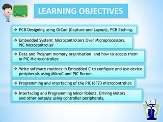
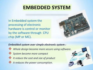
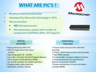
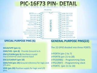
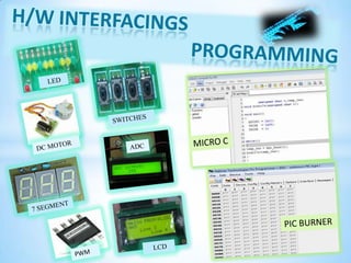
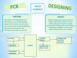
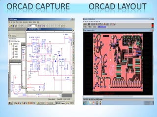
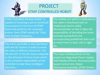
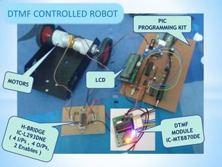
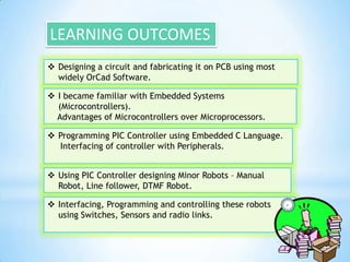
LEARNING OBJECTIVES
 Write software routines in Embedded C to configure and use device
peripherals using MikroC and PIC Burner.
 Data and Program memory organisation and how to access them
in PIC Microcontroller.
 Programming and interfacing of the PIC16F73 microcontroller.
 PCB Designing using OrCad (Capture and Layout), PCB Etching.
 Interfacing and Programming Minor Robots. Driving Motors
and other outputs using controller peripherals.
 Embedded System: Microcontrollers Over Microprocessors,
PIC Microcontroller
Embedded system over simple electronic system :
 Whole design become more secure using software.
 System become more compact
 It reduce the cost and size of product
 It reduces the power consumption.
In Embedded system the
processing of electronic
hardware is control or monitor
by the software through CPU
chip (MP or MC).
 Peripheral Interface Controller
 Developed by Microchip Technology in 1975
 Microcontrollers
 NOT Microprocessors
 Microprocessor system with number of
components (EEPROM, RAM, I/O Support)
High performance RISC CPU.
Only 35 single word instructions
to learn.
Operating speed: DC - 20 MHz .
Up to 8K x 14 words of FLASH Program Memory.
192 x 8 bytes of Data Memory (RAM).
on-chip RC oscillator for reliable operation.
Programmable code protection.
Selectable oscillator options.
SPECIAL
FEATURES
Timer0: 8-bit timer/counter with 8-bit
prescaler.
Timer1: 16-bit timer/counter with prescaler.
Two PWM modules
5-channel 8bit Analog-to-Digital converter.
Universal Synchronous Asynchronous
Receiver Transmitter (USART).
Brown-out detection circuitry for Brown-
out Reset (BOR).
PERIPHERAL
FEATURES
SPECIAL PURPOSE PINS (6)
MCLR/VPP-(pin 1):
GND/VSS –(pin 8): Provide Ground to it.
OSC1/CLKIN-(pin 9):Oscillator crystal
input/external clock source input
OSC2/CLKOUT-(pin 10)
GND/VSS (pin 19):Ground reference for logic and
I/O pins
VDD (pin 20):Positive supply for logic and I/O
pins.
GENERAL PURPOSE PINS(22)
The 22 GPIO divided into three PORTS.
PORTA (pin 2 to 7)
PORTB (pin 21 to 28)
PGD(RB6) : Programming Data
PGC(RB7) : Programming clock
PORTC -(pin 11 to 18)
ORCAD
(CADENCE)
CAPTURE
The Capture CIS links component
information, such as PCB package
footprint data where one can place
parts; wires; buses and draw graphics
with the circuit symbol in the
schematic and create the net list
LAYOUT
OrCAD's Layout gives functionality to
define placement, perform critical
routing, design rule check, Copper
pouring, Drill settings, Silk screen setting
and design complete circuit boards
where autorouting is not needed.
CAPTURE
LIBRARIES
FOOTPRINT
LIBRARIES
LAYOUT
GERBER
TOOLS
GERBER AND
DRILL FILES
GERBER AND
PLOTTER
DRAWING
BOTTOM LAYER LAYOUT PCB ETCHING
DRILLING AND SOLDERING PIC KIT
PROJECT
DTMF CONTROLLED ROBOT
The major building blocks of this
project are Regulated Power Supply,
GSM Modem/Phone, Microcontroller
based Control Unit, Robot
Mechanical Assembly, DTMF Drivers.
DTMF Controlled Wireless Robot” is
capable of receiving a set of command
(instructions) in the form of DTMF
tones and performs the necessary
actions. Here DTMF stands for “Dual
tone multiple frequency.
The mobile unit which is dedicated at
the robot is interfaced with an
intellectual device called
Microcontroller so that it takes the
responsibility of decoding the tones
received and perform the
corresponding predefined tasks such
as move front or back, left or right
etc.
The micro controller is also interfaced
with few DC motors in order to move
the robot in different directions. The
ON and OFF of the DC motors depends
on the direction it has to move which
is the complete responsibility of the
controller to take those intelligent
decisions.
LCD
PIC
PROGRAMMING KIT
DTMF CONTROLLED ROBOT
LEARNING OUTCOMES
 Designing a circuit and fabricating it on PCB using most
widely OrCad Software.
 I became familiar with Embedded Systems
(Microcontrollers).
Advantages of Microcontrollers over Microprocessors.
 Programming PIC Controller using Embedded C Language.
Interfacing of controller with Peripherals.
 Using PIC Controller designing Minor Robots – Manual
Robot, Line follower, DTMF Robot.
 Interfacing, Programming and controlling these robots
using Switches, Sensors and radio links.

Embedded System - Dtmf robot

  • 2.
    LEARNING OBJECTIVES  Writesoftware routines in Embedded C to configure and use device peripherals using MikroC and PIC Burner.  Data and Program memory organisation and how to access them in PIC Microcontroller.  Programming and interfacing of the PIC16F73 microcontroller.  PCB Designing using OrCad (Capture and Layout), PCB Etching.  Interfacing and Programming Minor Robots. Driving Motors and other outputs using controller peripherals.  Embedded System: Microcontrollers Over Microprocessors, PIC Microcontroller
  • 3.
    Embedded system oversimple electronic system :  Whole design become more secure using software.  System become more compact  It reduce the cost and size of product  It reduces the power consumption. In Embedded system the processing of electronic hardware is control or monitor by the software through CPU chip (MP or MC).
  • 4.
     Peripheral InterfaceController  Developed by Microchip Technology in 1975  Microcontrollers  NOT Microprocessors  Microprocessor system with number of components (EEPROM, RAM, I/O Support) High performance RISC CPU. Only 35 single word instructions to learn. Operating speed: DC - 20 MHz . Up to 8K x 14 words of FLASH Program Memory. 192 x 8 bytes of Data Memory (RAM). on-chip RC oscillator for reliable operation. Programmable code protection. Selectable oscillator options. SPECIAL FEATURES Timer0: 8-bit timer/counter with 8-bit prescaler. Timer1: 16-bit timer/counter with prescaler. Two PWM modules 5-channel 8bit Analog-to-Digital converter. Universal Synchronous Asynchronous Receiver Transmitter (USART). Brown-out detection circuitry for Brown- out Reset (BOR). PERIPHERAL FEATURES
  • 5.
    SPECIAL PURPOSE PINS(6) MCLR/VPP-(pin 1): GND/VSS –(pin 8): Provide Ground to it. OSC1/CLKIN-(pin 9):Oscillator crystal input/external clock source input OSC2/CLKOUT-(pin 10) GND/VSS (pin 19):Ground reference for logic and I/O pins VDD (pin 20):Positive supply for logic and I/O pins. GENERAL PURPOSE PINS(22) The 22 GPIO divided into three PORTS. PORTA (pin 2 to 7) PORTB (pin 21 to 28) PGD(RB6) : Programming Data PGC(RB7) : Programming clock PORTC -(pin 11 to 18)
  • 7.
    ORCAD (CADENCE) CAPTURE The Capture CISlinks component information, such as PCB package footprint data where one can place parts; wires; buses and draw graphics with the circuit symbol in the schematic and create the net list LAYOUT OrCAD's Layout gives functionality to define placement, perform critical routing, design rule check, Copper pouring, Drill settings, Silk screen setting and design complete circuit boards where autorouting is not needed. CAPTURE LIBRARIES FOOTPRINT LIBRARIES LAYOUT GERBER TOOLS GERBER AND DRILL FILES GERBER AND PLOTTER DRAWING
  • 9.
    BOTTOM LAYER LAYOUTPCB ETCHING DRILLING AND SOLDERING PIC KIT
  • 10.
    PROJECT DTMF CONTROLLED ROBOT Themajor building blocks of this project are Regulated Power Supply, GSM Modem/Phone, Microcontroller based Control Unit, Robot Mechanical Assembly, DTMF Drivers. DTMF Controlled Wireless Robot” is capable of receiving a set of command (instructions) in the form of DTMF tones and performs the necessary actions. Here DTMF stands for “Dual tone multiple frequency. The mobile unit which is dedicated at the robot is interfaced with an intellectual device called Microcontroller so that it takes the responsibility of decoding the tones received and perform the corresponding predefined tasks such as move front or back, left or right etc. The micro controller is also interfaced with few DC motors in order to move the robot in different directions. The ON and OFF of the DC motors depends on the direction it has to move which is the complete responsibility of the controller to take those intelligent decisions.
  • 11.
  • 12.
    LEARNING OUTCOMES  Designinga circuit and fabricating it on PCB using most widely OrCad Software.  I became familiar with Embedded Systems (Microcontrollers). Advantages of Microcontrollers over Microprocessors.  Programming PIC Controller using Embedded C Language. Interfacing of controller with Peripherals.  Using PIC Controller designing Minor Robots – Manual Robot, Line follower, DTMF Robot.  Interfacing, Programming and controlling these robots using Switches, Sensors and radio links.