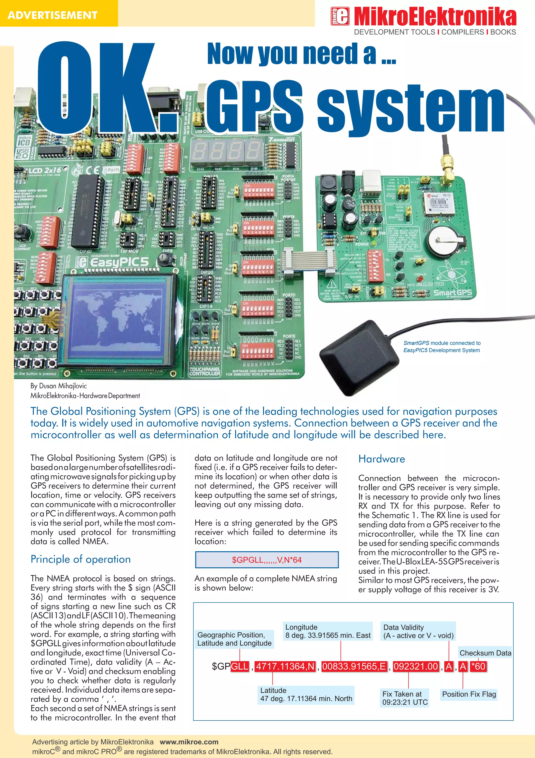
SlideShare a Scribd company logo
Advertising article by MikroElektronika www.mikroe.com
mikroC® and mikroC PRO® are registered trademarks of MikroElektronika. All rights reserved.
ADVERTISEMENT
OK.OK.
The Global Positioning System (GPS) is one of the leading technologies used for navigation purposes
today. It is widely used in automotive navigation systems. Connection between a GPS receiver and the
microcontroller as well as determination of latitude and longitude will be described here.
GPS systemGPS system
Now you need a ...Now you need a ...
By Dusan Mihajlovic
MikroElektronika-HardwareDepartment
SmartGPS module connected to
EasyPIC5 Development System
data on latitude and longitude are not
fixed (i.e. if a GPS receiver fails to deter-
mine its location) or when other data is
not determined, the GPS receiver will
keep outputting the same set of strings,
leaving out any missing data.
Here is a string generated by the GPS
receiver which failed to determine its
location:
An example of a complete NMEA string
is shown below:
The Global Positioning System (GPS) is
basedonalargenumberofsatellitesradi-
atingmicrowavesignalsforpickingupby
GPS receivers to determine their current
location, time or velocity. GPS receivers
can communicate with a microcontroller
oraPCindifferentways.Acommonpath
is via the serial port, while the most com-
monly used protocol for transmitting
data is called NMEA.
Principle of operation
The NMEA protocol is based on strings.
Every string starts with the $ sign (ASCII
36) and terminates with a sequence
of signs starting a new line such as CR
(ASCII13)andLF(ASCII10).Themeaning
of the whole string depends on the first
word. For example, a string starting with
$GPGLLgivesinformationaboutlatitude
and longitude, exact time (Universal Co-
ordinated Time), data validity (A – Ac-
tive or V - Void) and checksum enabling
you to check whether data is regularly
received. Individual data items are sepa-
rated by a comma ‘ , ’.
Each second a set of NMEA strings is sent
to the microcontroller. In the event that
Hardware
Connection between the microcon-
troller and GPS receiver is very simple.
It is necessary to provide only two lines
RX and TX for this purpose. Refer to
the Schematic 1. The RX line is used for
sending data from a GPS receiver to the
microcontroller, while the TX line can
be used for sending specific commands
from the microcontroller to the GPS re-
ceiver.TheU-BloxLEA-5SGPSreceiveris
used in this project.
Similar to most GPS receivers, the pow-
er supply voltage of this receiver is 3V.
$GPGLL,,,,,,V,N*64
Example 1: Program to demonstrate operation of LEA -5S module
... making it simple
Since the PIC18F4520 microcontroller
uses a 5V supply voltage to operate, it is
necessary to use a voltage level transla-
tor to convert the Logic One voltage level
from 3.3V to 5V.
In this example, a graphic display with
a resolution of 128x64 pixels displays a
world map with the cursor pointing to
your location on the globe.
Software
As you can see, the program code be-
ing fed into the microcontroller is very
short. Nearly half the code constitutes
a bitmap converted into an appropriate
set of data. Such conversion enables the
microcontroller to display the map. The
rest of code consists of receiving NMEA
stringsfromtheGPSreceiver,calculating
latitude and longitude, scaling data to
match the display resolution of 128x64
pixels and positioning the cursor at the
specified location.
SOFTWARE AND HARDWARE SOLUTIONS FOR EMBEDDED WORLD www.mikroe.com
Microchip®, logo and combinations thereof, PIC® and others are registered trademarks or trademarks of Microchip Corporation or its subsidiaries.
Other terms and product names may be trademarks of other companies.
Other mikroC PRO for PIC functions used in program:
Usart_Init() strstr()
Usart_Read() Delay_ms()
Schematic 1. Connecting the LEA-5S
module to a PIC18F4520
char txt[768];
signed int latitude, longitude;
char *string;
int i;
unsigned short ready;
extern const unsigned short world_bmp[1024];
char GLCD_DataPort at PORTD;
sbit GLCD_CS1 at RB0_bit; sbitGLCD_CS1_DirectionatTRISB0_bit;
sbit GLCD_CS2 at RB1_bit; sbitGLCD_CS2_DirectionatTRISB1_bit;
sbit GLCD_RS at RB2_bit; sbitGLCD_RS_DirectionatTRISB2_bit;
sbit GLCD_RW at RB3_bit; sbitGLCD_RW_DirectionatTRISB3_bit;
sbit GLCD_EN at RB4_bit; sbitGLCD_EN_DirectionatTRISB4_bit;
sbit GLCD_RST at RB5_bit; sbitGLCD_RST_DirectionatTRISB5_bit;
void interrupt() {
if (PIR1.F0 == 1) { //if interrupt is generated by TMR1IF
//Stop Timer 1:
T1CON.F0 = 0; //Set TMR1ON to 0
ready = 1; //set data ready
i = 0; //reset array counter
PIR1.F0 = 0; //Set TMR1IF to 0
}
if (PIR1.F5 == 1) { //if interrupt is generated by RCIF
txt[i++] = UART1_Read();
if (i == 768) i = 0;
//Stop Timer 1:
T1CON.F0 = 0; //Set TMR1ON to 0
//Timer1 starts counting from 15536:
TMR1L = 0xB0;
TMR1H = 0x3C;
//Start Timer 1:
T1CON.F0 = 1; //Set TMR1ON to 1
PIR1.F5 = 0; //Set RCIF to 0
}
}
void Display_Cursor(signed int lat, signed int lon) {
unsigned char latitude_y, longitude_x;
//Latitude and Longitude scaling for 128x64 display:
//Latitude: Input range is -90 to 90 degrees
//Longitude: Input range is -180 to 180 degrees
latitude_y = ((61*(90 - lat))/180) + 1;
longitude_x = ((125*(lon + 180))/360) + 1;
//Cursor drawing:
Glcd_Dot(longitude_x,latitude_y,2); //Centar dot
Glcd_Dot(longitude_x-1,latitude_y,2); //Left dot
Glcd_Dot(longitude_x+1,latitude_y,2); //Right dot
Glcd_Dot(longitude_x,latitude_y-1,2); //Uper dot
Glcd_Dot(longitude_x,latitude_y+1,2); //Lower dot
Delay_ms(500);
Glcd_Image( world_bmp ); //Display World
//map on the GLCD
}
void main() {
ADCON1 = 0x0F; // Set AN pins to Digital I/O
GLCD_Init();
Glcd_Set_Font(font5x7, 5, 7, 32);
Glcd_Fill(0x00);
Delay_ms(100);
ready = 0;
//Set Timer1 Prescaler to 1:8
T1CON.F5 = 1; //Set TCKPS1 to 1
T1CON.F4 = 1; //Set TCKPS0 to 1
//Enable Timer1 interrupt:
PIE1.F0 = 1; //Set TMR1IE to 1
//Timer1 starts counting from 15536:
TMR1L = 0xB0;
TMR1H = 0x3C;
//Clear Timer1 interrupt flag:
PIR1.F0 = 0; //Set TMR1IF to 0
//Note: Timer1 is set to generate interrupt on 50ms interval
UART1_Init(9600);
//Enable Usart Receiver interrupt:
PIE1.F5 = 1; //Set RCIE to 1
//Enable Global interrupt and Peripheral interrupt:
INTCON.F7 = 1; //Set GIE to 1
INTCON.F6 = 1; //Set PEIE to 1
//Start Timer 1:
T1CON.F0 = 1; //Set TMR1ON to 1
Glcd_Image( world_bmp ); //DisplayWorldmapontheGLCD
while(1)
{
RCSTA.F1 = 0; //Set OERR to 0
RCSTA.F2 = 0; //Set FERR to 0
if(ready == 1) { //if the data in txt array is ready do:
ready = 0;
string = strstr(txt,‰$GPGLL‰);
if(string != 0) { //If txt array contains „$GPGLL‰ string we proceed...
if(string[7] != Â,Ê) { //if „$GPGLL‰ NMEA message have Â,Ê sign in the 8-th
//positionitmeansthatthaGPSreceiverdoesnothaveFIXedposition!
latitude = (string[7]-48)*10 + (string[8]-48);
longitude = (string[20]-48)*100 + (string[21]-48)*10 + (string[22]-48);
if(string[18] == ÂSÊ) { //ifthelatitudeisintheSouthdirectionithasminussign
latitude = 0 - latitude;
}
if(string[32] == ÂWÊ) { //ifthelongitudeisintheWestdirectionithasminussign
longitude = 0 - longitude;
}
Display_Cursor(latitude, longitude); //Display the cursor on the world map
}
}
}
}
}
unsigned char const World_bmp[1024] = {
255,129,1,1,1,129,129,129,129,193,129,129,129,129,129,129,129,129,129,129,129,
225,161,161,97,97,209,209,129,49,49,201,201,201,201,97,205,205,129,137,25,5
7,57,57,121,249,249,249,249,249,253,253,121,121,113,9,9,1,1,1,1,1,1,1,1,1,1,17,17,
145,145,145,145,129,129,129,1,1,1,1,9,73,73,73,73,193,65,65,129,129,193,193,129,
193,193,241,241,241,241,225,225,225,193,193,193,193,193,193,193,193,193,129,
193,193,225,225,129,129,129,129,129,129,129,129,129,129,129,255,255,1,33,17,17,
15,15,15,15,15,7,7,7,7,15,15,31,63,63,63,63,255,255,255,255,255,255,255,255,251,2
51,240,240,240,240,226,252,252,249,249,250,240,240,1,1,1,1,3,1,1,0,0,0,0,0,2,2,0,0,
0,24,24,224,224,224,224,244,239,239,255,255,255,255,255,255,255,255,255,254,25
4,255,255,255,255,255,255,255,255,255,255,255,255,255,255,255,255,255,255,255,
255,255,255,255,255,255,255,255,255,255,255,255,255,95,95,3,3,3,3,63,15,15,3,3,3,
3,3,1,255,255,0,0,0,0,0,0,0,0,0,0,0,0,0,0,0,0,0,0,0,0,15,63,63,255,255,255,255,255,63,
63,63,63,63,63,63,135,135,1,1,0,0,0,0,0,0,0,0,0,0,0,0,0,0,0,0,0,192,192,192,243,243,2
51,251,251,251,251,247,231,231,243,247,247,247,230,236,124,124,255,255,220,60,
61,61,63,126,255,255,255,255,255,255,255,255,255,255,255,255,255,255,255,255,2
55,255,255,59,59,3,7,3,27,12,7,7,0,0,0,0,0,0,0,0,0,0,0,0,0,255,255,0,0,0,0,1,1,0,0,0,0,0
,0,0,0,0,0,0,0,0,0,0,0,0,0,0,1,1,3,6,6,13,13,13,13,17,242,242,242,242,240,224,224,192,
192,192,192,0,0,0,0,0,0,0,0,0,0,31,31,31,63,63,63,63,63,63,255,255,255,255,255,255
,255,255,255,255,248,248,247,247,55,3,3,3,3,0,1,1,3,3,15,15,7,0,0,1,1,3,3,239,15,15,
1,129,224,174,46,128,0,128,0,0,0,0,0,0,0,0,0,0,0,0,0,0,0,0,0,255,255,0,0,0,0,0,0,0,0,0,
0,0,0,0,0,0,0,0,0,0,0,0,0,0,0,0,0,0,0,0,0,0,0,0,0,3,63,63,255,255,255,255,255,255,255,
255,255,255,254,254,12,12,0,0,0,0,0,0,0,0,0,0,0,0,0,0,1,255,255,255,255,255,255,25
5,255,255,63,63,193,193,240,0,0,0,0,0,0,0,0,0,0,0,0,0,0,0,0,0,0,0,3,3,4,9,129,193,192,
225,224,226,224,242,227,227,228,228,8,8,0,0,0,0,0,0,0,0,0,255,255,0,0,0,0,0,0,0,0,0,
0,0,0,0,0,0,0,0,0,0,0,0,0,0,0,0,0,0,0,0,0,0,0,0,0,0,0,0,255,255,255,31,31,15,15,15,15,1,
0,0,0,0,0,0,0,0,0,0,0,0,0,0,0,0,0,0,0,3,3,15,15,15,15,15,3,3,0,0,1,1,0,0,0,0,0,0,0,0,0,0,0,
0,0,0,0,0,0,0,0,0,0,0,0,0,7,15,15,7,7,7,7,7,31,31,127,127,70,70,0,0,0,0,0,0,208,208,0,2
55,255,0,0,0,0,0,0,0,0,0,0,0,0,0,0,0,0,0,0,0,0,0,0,0,0,0,0,0,0,0,0,0,0,0,0,0,0,0,135,135,1
93,64,68,0,0,0,0,0,0,0,0,0,0,0,0,0,0,0,0,0,0,0,0,0,0,0,0,0,0,0,0,0,0,0,0,0,0,0,0,0,128,128
,128,128,128,128,0,0,0,0,0,0,0,0,0,0,0,0,0,128,128,128,128,128,128,0,0,0,0,0,0,128,0
,0,0,0,0,0,0,0,0,0,0,0,0,0,0,255,255,240,240,240,240,248,248,248,248,248,248,248,2
48,248,252,252,252,252,252,252,252,252,252,252,252,252,252,252,252,252,252,25
2,252,252,252,252,254,254,255,255,255,252,252,248,248,248,248,248,248,248,248,
248,248,248,252,252,252,254,254,254,254,254,255,255,255,255,255,255,255,255,2
55,255,255,255,255,255,254,254,255,255,255,255,255,255,255,255,255,255,255,25
5,255,255,255,255,255,255,255,255,255,255,255,255,255,255,255,255,255,255,255
,255,255,255,255,255,255,255,255,255,255,255,255,250,250,250,216,216,248,255};
Code for this example written for PIC® microcontrollers in C, Basic and Pascal as well as
the programs written for dsPIC® and AVR® microcontrollers can be found on our website:
www.mikroe.com/en/article/GOTO
mikroC PRO
for PIC
Written in compiler
Glcd_box() Draw filled box
Glcd_circle() Draw circle
Glcd_Dot() Draw dot*
Glcd_Fill() Delete/fill display*
Glcd_H_Line() Draw horizontal line
Glcd_Image() Import image*
Glcd_Init() LCD display initialization*
Glcd_Line() Draw line
Glcd_Read_Data() Read data from LCD
Glcd_Rectangle() Draw rectangle
Glcd_Set_Font() Select font*
Glcd_Set_Page() Select page
Glcd_Set_Side() Select side of display
Glcd_Set_X() Determine X coordinate
Glcd_V_line() Draw vertical line
Glcd_Write_Char() Write character
Glcd_Write_Data() Write data
Glcd_Write_Text() Write text
* Glcd library functions used in the program
Functions used in the program
mikroC PRO for PIC® library editor
with ready to use libraries such as:
GLCD, Ethernet, CAN, SD/MMC etc.

More Related Content

What's hot

Uart VHDL RTL design tutorial
Uart VHDL RTL design tutorialUart VHDL RTL design tutorial
Uart VHDL RTL design tutorial
Nabil Chouba
 
MIPI DevCon 2016: Implementing MIPI C-PHY
MIPI DevCon 2016: Implementing MIPI C-PHYMIPI DevCon 2016: Implementing MIPI C-PHY
MIPI DevCon 2016: Implementing MIPI C-PHY
MIPI Alliance
 
Wireless data transmission through uart port using arm & rf transceiver
Wireless data transmission through uart port using arm & rf transceiverWireless data transmission through uart port using arm & rf transceiver
Wireless data transmission through uart port using arm & rf transceiver
eSAT Publishing House
 
Lcd module interface with xilinx software using verilog
Lcd module interface with xilinx software using verilogLcd module interface with xilinx software using verilog
Lcd module interface with xilinx software using verilog
sumedh23
 
DEF CON 23 - Rodringo Almeida - embedded system design from electronics
DEF CON 23 - Rodringo Almeida - embedded system design from electronics DEF CON 23 - Rodringo Almeida - embedded system design from electronics
DEF CON 23 - Rodringo Almeida - embedded system design from electronics
Felipe Prado
 
Lalit Singh FPGA resume
Lalit Singh FPGA resumeLalit Singh FPGA resume
Lalit Singh FPGA resumeLalit singh
 
Real Time Clock Interfacing with FPGA
Real Time Clock Interfacing with FPGAReal Time Clock Interfacing with FPGA
Real Time Clock Interfacing with FPGA
Mafaz Ahmed
 
Analog to Digital Converter
Analog to Digital ConverterAnalog to Digital Converter
Analog to Digital Converter
Ariel Tonatiuh Espindola
 
MX Lap Timer - An automatic stopwatch for Motocross
MX Lap Timer - An automatic stopwatch for MotocrossMX Lap Timer - An automatic stopwatch for Motocross
MX Lap Timer - An automatic stopwatch for Motocross
Guilherme Pohl
 
Versatile modular electronics for rapid design and development
Versatile modular electronics for rapid design and developmentVersatile modular electronics for rapid design and development
Versatile modular electronics for rapid design and development
Gokul Nair
 
Design of VGA Controller using VHDL for LCD Display using FPGA
Design of VGA Controller using VHDL for LCD Display using  FPGADesign of VGA Controller using VHDL for LCD Display using  FPGA
Design of VGA Controller using VHDL for LCD Display using FPGA
IJMER
 
Robotic Project - published paper
Robotic Project - published paperRobotic Project - published paper
Robotic Project - published paperRobert Rosier
 
15CSL48 MP&MC manual
15CSL48 MP&MC manual15CSL48 MP&MC manual
15CSL48 MP&MC manual
RLJIT
 
Camera training by Sergio Aguirre
Camera training by Sergio AguirreCamera training by Sergio Aguirre
Camera training by Sergio Aguirresergio_a_aguirre
 
Vlsi es-lab-manual
Vlsi es-lab-manualVlsi es-lab-manual
Vlsi es-lab-manual
twinkleratna
 
Design and Implementation of 64 Bit RISC Processor Using System.pdf
Design and Implementation of 64 Bit RISC Processor Using System.pdfDesign and Implementation of 64 Bit RISC Processor Using System.pdf
Design and Implementation of 64 Bit RISC Processor Using System.pdf
ChowdappaKv1
 
EMC2 Xilinx SDSoC presentation
EMC2 Xilinx SDSoC presentationEMC2 Xilinx SDSoC presentation
EMC2 Xilinx SDSoC presentation
Sundance Multiprocessor Technology Ltd.
 
Simulation power analysis low power vlsi
Simulation power analysis   low power vlsiSimulation power analysis   low power vlsi
Simulation power analysis low power vlsi
GargiKhanna1
 
Interfacing UART with tms320C6745
Interfacing UART with tms320C6745Interfacing UART with tms320C6745
Interfacing UART with tms320C6745
Pantech ProLabs India Pvt Ltd
 

What's hot (20)

Uart VHDL RTL design tutorial
Uart VHDL RTL design tutorialUart VHDL RTL design tutorial
Uart VHDL RTL design tutorial
 
MIPI DevCon 2016: Implementing MIPI C-PHY
MIPI DevCon 2016: Implementing MIPI C-PHYMIPI DevCon 2016: Implementing MIPI C-PHY
MIPI DevCon 2016: Implementing MIPI C-PHY
 
Wireless data transmission through uart port using arm & rf transceiver
Wireless data transmission through uart port using arm & rf transceiverWireless data transmission through uart port using arm & rf transceiver
Wireless data transmission through uart port using arm & rf transceiver
 
Lcd module interface with xilinx software using verilog
Lcd module interface with xilinx software using verilogLcd module interface with xilinx software using verilog
Lcd module interface with xilinx software using verilog
 
DEF CON 23 - Rodringo Almeida - embedded system design from electronics
DEF CON 23 - Rodringo Almeida - embedded system design from electronics DEF CON 23 - Rodringo Almeida - embedded system design from electronics
DEF CON 23 - Rodringo Almeida - embedded system design from electronics
 
Lalit Singh FPGA resume
Lalit Singh FPGA resumeLalit Singh FPGA resume
Lalit Singh FPGA resume
 
Real Time Clock Interfacing with FPGA
Real Time Clock Interfacing with FPGAReal Time Clock Interfacing with FPGA
Real Time Clock Interfacing with FPGA
 
Analog to Digital Converter
Analog to Digital ConverterAnalog to Digital Converter
Analog to Digital Converter
 
MX Lap Timer - An automatic stopwatch for Motocross
MX Lap Timer - An automatic stopwatch for MotocrossMX Lap Timer - An automatic stopwatch for Motocross
MX Lap Timer - An automatic stopwatch for Motocross
 
Pc 104 series 1 application showcase
Pc 104 series 1 application showcasePc 104 series 1 application showcase
Pc 104 series 1 application showcase
 
Versatile modular electronics for rapid design and development
Versatile modular electronics for rapid design and developmentVersatile modular electronics for rapid design and development
Versatile modular electronics for rapid design and development
 
Design of VGA Controller using VHDL for LCD Display using FPGA
Design of VGA Controller using VHDL for LCD Display using  FPGADesign of VGA Controller using VHDL for LCD Display using  FPGA
Design of VGA Controller using VHDL for LCD Display using FPGA
 
Robotic Project - published paper
Robotic Project - published paperRobotic Project - published paper
Robotic Project - published paper
 
15CSL48 MP&MC manual
15CSL48 MP&MC manual15CSL48 MP&MC manual
15CSL48 MP&MC manual
 
Camera training by Sergio Aguirre
Camera training by Sergio AguirreCamera training by Sergio Aguirre
Camera training by Sergio Aguirre
 
Vlsi es-lab-manual
Vlsi es-lab-manualVlsi es-lab-manual
Vlsi es-lab-manual
 
Design and Implementation of 64 Bit RISC Processor Using System.pdf
Design and Implementation of 64 Bit RISC Processor Using System.pdfDesign and Implementation of 64 Bit RISC Processor Using System.pdf
Design and Implementation of 64 Bit RISC Processor Using System.pdf
 
EMC2 Xilinx SDSoC presentation
EMC2 Xilinx SDSoC presentationEMC2 Xilinx SDSoC presentation
EMC2 Xilinx SDSoC presentation
 
Simulation power analysis low power vlsi
Simulation power analysis   low power vlsiSimulation power analysis   low power vlsi
Simulation power analysis low power vlsi
 
Interfacing UART with tms320C6745
Interfacing UART with tms320C6745Interfacing UART with tms320C6745
Interfacing UART with tms320C6745
 

Viewers also liked

Using Timers in PIC18F Microcontrollers
Using Timers in PIC18F MicrocontrollersUsing Timers in PIC18F Microcontrollers
Using Timers in PIC18F MicrocontrollersCorrado Santoro
 
Serial EEPROM
Serial EEPROMSerial EEPROM
Serial EEPROM
Raghav Shetty
 
GSM 1308 MODEM CONTROL USING PIC-16F877A MICROCONTROLLER
GSM 1308 MODEM CONTROL USING PIC-16F877A MICROCONTROLLERGSM 1308 MODEM CONTROL USING PIC-16F877A MICROCONTROLLER
GSM 1308 MODEM CONTROL USING PIC-16F877A MICROCONTROLLERMd. Moktarul Islam
 
PIC timer programming
PIC timer programmingPIC timer programming
PIC timer programming
Akash Puri
 
Pic Mini Project Board
Pic Mini Project BoardPic Mini Project Board
Pic Mini Project Board
Raghav Shetty
 
our 1st project
our 1st projectour 1st project
our 1st project
mohamed sarhan
 
Analog I/O in PIC16F877A
Analog I/O in PIC16F877AAnalog I/O in PIC16F877A
Analog I/O in PIC16F877A
Mohamed Bedair
 
Pic18f4550
Pic18f4550Pic18f4550
Pic18f4550
Felix Alvarez
 
8 Channel Relay Board-Bluetooth
8 Channel Relay Board-Bluetooth8 Channel Relay Board-Bluetooth
8 Channel Relay Board-Bluetooth
Raghav Shetty
 
Embedded System - Dtmf robot
Embedded System - Dtmf robotEmbedded System - Dtmf robot
Embedded System - Dtmf robot
Abhishek Sood
 
I2C Protocol
I2C ProtocolI2C Protocol
I2C Protocol
Abhijeet kapse
 
Autocad Electrical 2011 Overview Brochure
Autocad Electrical 2011 Overview BrochureAutocad Electrical 2011 Overview Brochure
Autocad Electrical 2011 Overview BrochureApplied Engineering
 
Read and Understand The Electrical Diagram
Read and Understand The Electrical DiagramRead and Understand The Electrical Diagram
Read and Understand The Electrical Diagram
Mohammud Hanif Dewan M.Phil.
 
Wireless Radio Frequency Module Using PIC Microcontroller.
Wireless Radio Frequency Module Using PIC Microcontroller.Wireless Radio Frequency Module Using PIC Microcontroller.
Wireless Radio Frequency Module Using PIC Microcontroller.
Abee Sharma
 
Pic microcontroller step by step your complete guide
Pic microcontroller step by step your complete guidePic microcontroller step by step your complete guide
Pic microcontroller step by step your complete guide
Ashraf Said AlMadhoun - Educational Engineering Team
 
I2C programming with C and Arduino
I2C programming with C and ArduinoI2C programming with C and Arduino
I2C programming with C and Arduino
sato262
 
Electrical Drawings and Schematics
Electrical Drawings and SchematicsElectrical Drawings and Schematics
Electrical Drawings and Schematics
Living Online
 
AutoCad Electrical
AutoCad ElectricalAutoCad Electrical
AutoCad Electrical
rahul_9463
 
PIC-MICROCONTROLLER TUTORIALS FOR BEGINNERS
PIC-MICROCONTROLLER TUTORIALS FOR BEGINNERSPIC-MICROCONTROLLER TUTORIALS FOR BEGINNERS
PIC-MICROCONTROLLER TUTORIALS FOR BEGINNERS
VISHNU KP
 

Viewers also liked (20)

Using Timers in PIC18F Microcontrollers
Using Timers in PIC18F MicrocontrollersUsing Timers in PIC18F Microcontrollers
Using Timers in PIC18F Microcontrollers
 
Serial EEPROM
Serial EEPROMSerial EEPROM
Serial EEPROM
 
GSM 1308 MODEM CONTROL USING PIC-16F877A MICROCONTROLLER
GSM 1308 MODEM CONTROL USING PIC-16F877A MICROCONTROLLERGSM 1308 MODEM CONTROL USING PIC-16F877A MICROCONTROLLER
GSM 1308 MODEM CONTROL USING PIC-16F877A MICROCONTROLLER
 
Pic16 f84a
Pic16 f84aPic16 f84a
Pic16 f84a
 
PIC timer programming
PIC timer programmingPIC timer programming
PIC timer programming
 
Pic Mini Project Board
Pic Mini Project BoardPic Mini Project Board
Pic Mini Project Board
 
our 1st project
our 1st projectour 1st project
our 1st project
 
Analog I/O in PIC16F877A
Analog I/O in PIC16F877AAnalog I/O in PIC16F877A
Analog I/O in PIC16F877A
 
Pic18f4550
Pic18f4550Pic18f4550
Pic18f4550
 
8 Channel Relay Board-Bluetooth
8 Channel Relay Board-Bluetooth8 Channel Relay Board-Bluetooth
8 Channel Relay Board-Bluetooth
 
Embedded System - Dtmf robot
Embedded System - Dtmf robotEmbedded System - Dtmf robot
Embedded System - Dtmf robot
 
I2C Protocol
I2C ProtocolI2C Protocol
I2C Protocol
 
Autocad Electrical 2011 Overview Brochure
Autocad Electrical 2011 Overview BrochureAutocad Electrical 2011 Overview Brochure
Autocad Electrical 2011 Overview Brochure
 
Read and Understand The Electrical Diagram
Read and Understand The Electrical DiagramRead and Understand The Electrical Diagram
Read and Understand The Electrical Diagram
 
Wireless Radio Frequency Module Using PIC Microcontroller.
Wireless Radio Frequency Module Using PIC Microcontroller.Wireless Radio Frequency Module Using PIC Microcontroller.
Wireless Radio Frequency Module Using PIC Microcontroller.
 
Pic microcontroller step by step your complete guide
Pic microcontroller step by step your complete guidePic microcontroller step by step your complete guide
Pic microcontroller step by step your complete guide
 
I2C programming with C and Arduino
I2C programming with C and ArduinoI2C programming with C and Arduino
I2C programming with C and Arduino
 
Electrical Drawings and Schematics
Electrical Drawings and SchematicsElectrical Drawings and Schematics
Electrical Drawings and Schematics
 
AutoCad Electrical
AutoCad ElectricalAutoCad Electrical
AutoCad Electrical
 
PIC-MICROCONTROLLER TUTORIALS FOR BEGINNERS
PIC-MICROCONTROLLER TUTORIALS FOR BEGINNERSPIC-MICROCONTROLLER TUTORIALS FOR BEGINNERS
PIC-MICROCONTROLLER TUTORIALS FOR BEGINNERS
 

Similar to Mikroc gps

Vehicle tracting system
Vehicle tracting systemVehicle tracting system
Vehicle tracting system
UVSofts Technologies
 
Iaetsd smart vehicle tracking system using gsm, gps and rc5
Iaetsd smart vehicle tracking system using gsm, gps and rc5Iaetsd smart vehicle tracking system using gsm, gps and rc5
Iaetsd smart vehicle tracking system using gsm, gps and rc5
Iaetsd Iaetsd
 
REAL-TIME VEHICLE LOCKING AND TRACKING SYSTEM USING GSM AND GPS TECHNOLOGY-A...
REAL-TIME VEHICLE  LOCKING AND TRACKING SYSTEM USING GSM AND GPS TECHNOLOGY-A...REAL-TIME VEHICLE  LOCKING AND TRACKING SYSTEM USING GSM AND GPS TECHNOLOGY-A...
REAL-TIME VEHICLE LOCKING AND TRACKING SYSTEM USING GSM AND GPS TECHNOLOGY-A...Sandeep Kunsoth
 
Data Acquisition
Data AcquisitionData Acquisition
Data Acquisition
azhar557
 
IRJET- Intelligent Security and Monitoring System for Vehicle
IRJET- Intelligent Security and Monitoring System for VehicleIRJET- Intelligent Security and Monitoring System for Vehicle
IRJET- Intelligent Security and Monitoring System for Vehicle
IRJET Journal
 
Design and implementation of GPS Tracker
Design and implementation of GPS TrackerDesign and implementation of GPS Tracker
Design and implementation of GPS TrackerVignesh Kannan
 
Intel galileo gen 2
Intel galileo gen 2Intel galileo gen 2
Intel galileo gen 2
srknec
 
IRJET- Ad-hoc Based Outdoor Positioning System
IRJET- Ad-hoc Based Outdoor Positioning SystemIRJET- Ad-hoc Based Outdoor Positioning System
IRJET- Ad-hoc Based Outdoor Positioning System
IRJET Journal
 
Kassem2009
Kassem2009Kassem2009
Kassem2009
lazchi
 
Embedded systems design @ defcon 2015
Embedded systems design @ defcon 2015Embedded systems design @ defcon 2015
Embedded systems design @ defcon 2015
Rodrigo Almeida
 
GPS Based Vehicle Location using ARM 7 LPC 2148
GPS Based Vehicle Location using ARM 7 LPC 2148GPS Based Vehicle Location using ARM 7 LPC 2148
GPS Based Vehicle Location using ARM 7 LPC 2148
IRJET Journal
 
AUTOMATIC VEHICLE ACCIDENT INFORMATION BY SMS SYSTEM 0
AUTOMATIC VEHICLE ACCIDENT INFORMATION BY SMS SYSTEM 0AUTOMATIC VEHICLE ACCIDENT INFORMATION BY SMS SYSTEM 0
AUTOMATIC VEHICLE ACCIDENT INFORMATION BY SMS SYSTEM 0
kailashgavare
 
Vectorization on x86: all you need to know
Vectorization on x86: all you need to knowVectorization on x86: all you need to know
Vectorization on x86: all you need to knowRoberto Agostino Vitillo
 
Bidirect visitor counter
Bidirect visitor counterBidirect visitor counter
Bidirect visitor counter
Electric&elctronics&engineeering
 
Localization using filtered dgps
Localization using filtered dgpsLocalization using filtered dgps
Localization using filtered dgps
eSAT Journals
 
IRJET- A Study on PRN Code Generation and Properties of C/A Code in GPS based...
IRJET- A Study on PRN Code Generation and Properties of C/A Code in GPS based...IRJET- A Study on PRN Code Generation and Properties of C/A Code in GPS based...
IRJET- A Study on PRN Code Generation and Properties of C/A Code in GPS based...
IRJET Journal
 
Design & development of embedded application
Design & development of embedded applicationDesign & development of embedded application
Design & development of embedded application
eSAT Publishing House
 

Similar to Mikroc gps (20)

Vehicle tracting system
Vehicle tracting systemVehicle tracting system
Vehicle tracting system
 
Iaetsd smart vehicle tracking system using gsm, gps and rc5
Iaetsd smart vehicle tracking system using gsm, gps and rc5Iaetsd smart vehicle tracking system using gsm, gps and rc5
Iaetsd smart vehicle tracking system using gsm, gps and rc5
 
REAL-TIME VEHICLE LOCKING AND TRACKING SYSTEM USING GSM AND GPS TECHNOLOGY-A...
REAL-TIME VEHICLE  LOCKING AND TRACKING SYSTEM USING GSM AND GPS TECHNOLOGY-A...REAL-TIME VEHICLE  LOCKING AND TRACKING SYSTEM USING GSM AND GPS TECHNOLOGY-A...
REAL-TIME VEHICLE LOCKING AND TRACKING SYSTEM USING GSM AND GPS TECHNOLOGY-A...
 
GPSGSM
GPSGSMGPSGSM
GPSGSM
 
Data Acquisition
Data AcquisitionData Acquisition
Data Acquisition
 
Embedded system
Embedded systemEmbedded system
Embedded system
 
IRJET- Intelligent Security and Monitoring System for Vehicle
IRJET- Intelligent Security and Monitoring System for VehicleIRJET- Intelligent Security and Monitoring System for Vehicle
IRJET- Intelligent Security and Monitoring System for Vehicle
 
Design and implementation of GPS Tracker
Design and implementation of GPS TrackerDesign and implementation of GPS Tracker
Design and implementation of GPS Tracker
 
Intel galileo gen 2
Intel galileo gen 2Intel galileo gen 2
Intel galileo gen 2
 
IRJET- Ad-hoc Based Outdoor Positioning System
IRJET- Ad-hoc Based Outdoor Positioning SystemIRJET- Ad-hoc Based Outdoor Positioning System
IRJET- Ad-hoc Based Outdoor Positioning System
 
Kassem2009
Kassem2009Kassem2009
Kassem2009
 
Embedded systems design @ defcon 2015
Embedded systems design @ defcon 2015Embedded systems design @ defcon 2015
Embedded systems design @ defcon 2015
 
GPS Based Vehicle Location using ARM 7 LPC 2148
GPS Based Vehicle Location using ARM 7 LPC 2148GPS Based Vehicle Location using ARM 7 LPC 2148
GPS Based Vehicle Location using ARM 7 LPC 2148
 
AUTOMATIC VEHICLE ACCIDENT INFORMATION BY SMS SYSTEM 0
AUTOMATIC VEHICLE ACCIDENT INFORMATION BY SMS SYSTEM 0AUTOMATIC VEHICLE ACCIDENT INFORMATION BY SMS SYSTEM 0
AUTOMATIC VEHICLE ACCIDENT INFORMATION BY SMS SYSTEM 0
 
Vectorization on x86: all you need to know
Vectorization on x86: all you need to knowVectorization on x86: all you need to know
Vectorization on x86: all you need to know
 
Bidirect visitor counter
Bidirect visitor counterBidirect visitor counter
Bidirect visitor counter
 
Localization using filtered dgps
Localization using filtered dgpsLocalization using filtered dgps
Localization using filtered dgps
 
FINISHED_CODE
FINISHED_CODEFINISHED_CODE
FINISHED_CODE
 
IRJET- A Study on PRN Code Generation and Properties of C/A Code in GPS based...
IRJET- A Study on PRN Code Generation and Properties of C/A Code in GPS based...IRJET- A Study on PRN Code Generation and Properties of C/A Code in GPS based...
IRJET- A Study on PRN Code Generation and Properties of C/A Code in GPS based...
 
Design & development of embedded application
Design & development of embedded applicationDesign & development of embedded application
Design & development of embedded application
 

Mikroc gps

  • 1. Advertising article by MikroElektronika www.mikroe.com mikroC® and mikroC PRO® are registered trademarks of MikroElektronika. All rights reserved. ADVERTISEMENT OK.OK. The Global Positioning System (GPS) is one of the leading technologies used for navigation purposes today. It is widely used in automotive navigation systems. Connection between a GPS receiver and the microcontroller as well as determination of latitude and longitude will be described here. GPS systemGPS system Now you need a ...Now you need a ... By Dusan Mihajlovic MikroElektronika-HardwareDepartment SmartGPS module connected to EasyPIC5 Development System data on latitude and longitude are not fixed (i.e. if a GPS receiver fails to deter- mine its location) or when other data is not determined, the GPS receiver will keep outputting the same set of strings, leaving out any missing data. Here is a string generated by the GPS receiver which failed to determine its location: An example of a complete NMEA string is shown below: The Global Positioning System (GPS) is basedonalargenumberofsatellitesradi- atingmicrowavesignalsforpickingupby GPS receivers to determine their current location, time or velocity. GPS receivers can communicate with a microcontroller oraPCindifferentways.Acommonpath is via the serial port, while the most com- monly used protocol for transmitting data is called NMEA. Principle of operation The NMEA protocol is based on strings. Every string starts with the $ sign (ASCII 36) and terminates with a sequence of signs starting a new line such as CR (ASCII13)andLF(ASCII10).Themeaning of the whole string depends on the first word. For example, a string starting with $GPGLLgivesinformationaboutlatitude and longitude, exact time (Universal Co- ordinated Time), data validity (A – Ac- tive or V - Void) and checksum enabling you to check whether data is regularly received. Individual data items are sepa- rated by a comma ‘ , ’. Each second a set of NMEA strings is sent to the microcontroller. In the event that Hardware Connection between the microcon- troller and GPS receiver is very simple. It is necessary to provide only two lines RX and TX for this purpose. Refer to the Schematic 1. The RX line is used for sending data from a GPS receiver to the microcontroller, while the TX line can be used for sending specific commands from the microcontroller to the GPS re- ceiver.TheU-BloxLEA-5SGPSreceiveris used in this project. Similar to most GPS receivers, the pow- er supply voltage of this receiver is 3V. $GPGLL,,,,,,V,N*64
  • 2. Example 1: Program to demonstrate operation of LEA -5S module ... making it simple Since the PIC18F4520 microcontroller uses a 5V supply voltage to operate, it is necessary to use a voltage level transla- tor to convert the Logic One voltage level from 3.3V to 5V. In this example, a graphic display with a resolution of 128x64 pixels displays a world map with the cursor pointing to your location on the globe. Software As you can see, the program code be- ing fed into the microcontroller is very short. Nearly half the code constitutes a bitmap converted into an appropriate set of data. Such conversion enables the microcontroller to display the map. The rest of code consists of receiving NMEA stringsfromtheGPSreceiver,calculating latitude and longitude, scaling data to match the display resolution of 128x64 pixels and positioning the cursor at the specified location. SOFTWARE AND HARDWARE SOLUTIONS FOR EMBEDDED WORLD www.mikroe.com Microchip®, logo and combinations thereof, PIC® and others are registered trademarks or trademarks of Microchip Corporation or its subsidiaries. Other terms and product names may be trademarks of other companies. Other mikroC PRO for PIC functions used in program: Usart_Init() strstr() Usart_Read() Delay_ms() Schematic 1. Connecting the LEA-5S module to a PIC18F4520 char txt[768]; signed int latitude, longitude; char *string; int i; unsigned short ready; extern const unsigned short world_bmp[1024]; char GLCD_DataPort at PORTD; sbit GLCD_CS1 at RB0_bit; sbitGLCD_CS1_DirectionatTRISB0_bit; sbit GLCD_CS2 at RB1_bit; sbitGLCD_CS2_DirectionatTRISB1_bit; sbit GLCD_RS at RB2_bit; sbitGLCD_RS_DirectionatTRISB2_bit; sbit GLCD_RW at RB3_bit; sbitGLCD_RW_DirectionatTRISB3_bit; sbit GLCD_EN at RB4_bit; sbitGLCD_EN_DirectionatTRISB4_bit; sbit GLCD_RST at RB5_bit; sbitGLCD_RST_DirectionatTRISB5_bit; void interrupt() { if (PIR1.F0 == 1) { //if interrupt is generated by TMR1IF //Stop Timer 1: T1CON.F0 = 0; //Set TMR1ON to 0 ready = 1; //set data ready i = 0; //reset array counter PIR1.F0 = 0; //Set TMR1IF to 0 } if (PIR1.F5 == 1) { //if interrupt is generated by RCIF txt[i++] = UART1_Read(); if (i == 768) i = 0; //Stop Timer 1: T1CON.F0 = 0; //Set TMR1ON to 0 //Timer1 starts counting from 15536: TMR1L = 0xB0; TMR1H = 0x3C; //Start Timer 1: T1CON.F0 = 1; //Set TMR1ON to 1 PIR1.F5 = 0; //Set RCIF to 0 } } void Display_Cursor(signed int lat, signed int lon) { unsigned char latitude_y, longitude_x; //Latitude and Longitude scaling for 128x64 display: //Latitude: Input range is -90 to 90 degrees //Longitude: Input range is -180 to 180 degrees latitude_y = ((61*(90 - lat))/180) + 1; longitude_x = ((125*(lon + 180))/360) + 1; //Cursor drawing: Glcd_Dot(longitude_x,latitude_y,2); //Centar dot Glcd_Dot(longitude_x-1,latitude_y,2); //Left dot Glcd_Dot(longitude_x+1,latitude_y,2); //Right dot Glcd_Dot(longitude_x,latitude_y-1,2); //Uper dot Glcd_Dot(longitude_x,latitude_y+1,2); //Lower dot Delay_ms(500); Glcd_Image( world_bmp ); //Display World //map on the GLCD } void main() { ADCON1 = 0x0F; // Set AN pins to Digital I/O GLCD_Init(); Glcd_Set_Font(font5x7, 5, 7, 32); Glcd_Fill(0x00); Delay_ms(100); ready = 0; //Set Timer1 Prescaler to 1:8 T1CON.F5 = 1; //Set TCKPS1 to 1 T1CON.F4 = 1; //Set TCKPS0 to 1 //Enable Timer1 interrupt: PIE1.F0 = 1; //Set TMR1IE to 1 //Timer1 starts counting from 15536: TMR1L = 0xB0; TMR1H = 0x3C; //Clear Timer1 interrupt flag: PIR1.F0 = 0; //Set TMR1IF to 0 //Note: Timer1 is set to generate interrupt on 50ms interval UART1_Init(9600); //Enable Usart Receiver interrupt: PIE1.F5 = 1; //Set RCIE to 1 //Enable Global interrupt and Peripheral interrupt: INTCON.F7 = 1; //Set GIE to 1 INTCON.F6 = 1; //Set PEIE to 1 //Start Timer 1: T1CON.F0 = 1; //Set TMR1ON to 1 Glcd_Image( world_bmp ); //DisplayWorldmapontheGLCD while(1) { RCSTA.F1 = 0; //Set OERR to 0 RCSTA.F2 = 0; //Set FERR to 0 if(ready == 1) { //if the data in txt array is ready do: ready = 0; string = strstr(txt,‰$GPGLL‰); if(string != 0) { //If txt array contains „$GPGLL‰ string we proceed... if(string[7] != Â,Ê) { //if „$GPGLL‰ NMEA message have Â,Ê sign in the 8-th //positionitmeansthatthaGPSreceiverdoesnothaveFIXedposition! latitude = (string[7]-48)*10 + (string[8]-48); longitude = (string[20]-48)*100 + (string[21]-48)*10 + (string[22]-48); if(string[18] == ÂSÊ) { //ifthelatitudeisintheSouthdirectionithasminussign latitude = 0 - latitude; } if(string[32] == ÂWÊ) { //ifthelongitudeisintheWestdirectionithasminussign longitude = 0 - longitude; } Display_Cursor(latitude, longitude); //Display the cursor on the world map } } } } } unsigned char const World_bmp[1024] = { 255,129,1,1,1,129,129,129,129,193,129,129,129,129,129,129,129,129,129,129,129, 225,161,161,97,97,209,209,129,49,49,201,201,201,201,97,205,205,129,137,25,5 7,57,57,121,249,249,249,249,249,253,253,121,121,113,9,9,1,1,1,1,1,1,1,1,1,1,17,17, 145,145,145,145,129,129,129,1,1,1,1,9,73,73,73,73,193,65,65,129,129,193,193,129, 193,193,241,241,241,241,225,225,225,193,193,193,193,193,193,193,193,193,129, 193,193,225,225,129,129,129,129,129,129,129,129,129,129,129,255,255,1,33,17,17, 15,15,15,15,15,7,7,7,7,15,15,31,63,63,63,63,255,255,255,255,255,255,255,255,251,2 51,240,240,240,240,226,252,252,249,249,250,240,240,1,1,1,1,3,1,1,0,0,0,0,0,2,2,0,0, 0,24,24,224,224,224,224,244,239,239,255,255,255,255,255,255,255,255,255,254,25 4,255,255,255,255,255,255,255,255,255,255,255,255,255,255,255,255,255,255,255, 255,255,255,255,255,255,255,255,255,255,255,255,255,95,95,3,3,3,3,63,15,15,3,3,3, 3,3,1,255,255,0,0,0,0,0,0,0,0,0,0,0,0,0,0,0,0,0,0,0,0,15,63,63,255,255,255,255,255,63, 63,63,63,63,63,63,135,135,1,1,0,0,0,0,0,0,0,0,0,0,0,0,0,0,0,0,0,192,192,192,243,243,2 51,251,251,251,251,247,231,231,243,247,247,247,230,236,124,124,255,255,220,60, 61,61,63,126,255,255,255,255,255,255,255,255,255,255,255,255,255,255,255,255,2 55,255,255,59,59,3,7,3,27,12,7,7,0,0,0,0,0,0,0,0,0,0,0,0,0,255,255,0,0,0,0,1,1,0,0,0,0,0 ,0,0,0,0,0,0,0,0,0,0,0,0,0,0,1,1,3,6,6,13,13,13,13,17,242,242,242,242,240,224,224,192, 192,192,192,0,0,0,0,0,0,0,0,0,0,31,31,31,63,63,63,63,63,63,255,255,255,255,255,255 ,255,255,255,255,248,248,247,247,55,3,3,3,3,0,1,1,3,3,15,15,7,0,0,1,1,3,3,239,15,15, 1,129,224,174,46,128,0,128,0,0,0,0,0,0,0,0,0,0,0,0,0,0,0,0,0,255,255,0,0,0,0,0,0,0,0,0, 0,0,0,0,0,0,0,0,0,0,0,0,0,0,0,0,0,0,0,0,0,0,0,0,0,3,63,63,255,255,255,255,255,255,255, 255,255,255,254,254,12,12,0,0,0,0,0,0,0,0,0,0,0,0,0,0,1,255,255,255,255,255,255,25 5,255,255,63,63,193,193,240,0,0,0,0,0,0,0,0,0,0,0,0,0,0,0,0,0,0,0,3,3,4,9,129,193,192, 225,224,226,224,242,227,227,228,228,8,8,0,0,0,0,0,0,0,0,0,255,255,0,0,0,0,0,0,0,0,0, 0,0,0,0,0,0,0,0,0,0,0,0,0,0,0,0,0,0,0,0,0,0,0,0,0,0,0,0,255,255,255,31,31,15,15,15,15,1, 0,0,0,0,0,0,0,0,0,0,0,0,0,0,0,0,0,0,0,3,3,15,15,15,15,15,3,3,0,0,1,1,0,0,0,0,0,0,0,0,0,0,0, 0,0,0,0,0,0,0,0,0,0,0,0,0,7,15,15,7,7,7,7,7,31,31,127,127,70,70,0,0,0,0,0,0,208,208,0,2 55,255,0,0,0,0,0,0,0,0,0,0,0,0,0,0,0,0,0,0,0,0,0,0,0,0,0,0,0,0,0,0,0,0,0,0,0,0,0,135,135,1 93,64,68,0,0,0,0,0,0,0,0,0,0,0,0,0,0,0,0,0,0,0,0,0,0,0,0,0,0,0,0,0,0,0,0,0,0,0,0,0,128,128 ,128,128,128,128,0,0,0,0,0,0,0,0,0,0,0,0,0,128,128,128,128,128,128,0,0,0,0,0,0,128,0 ,0,0,0,0,0,0,0,0,0,0,0,0,0,0,255,255,240,240,240,240,248,248,248,248,248,248,248,2 48,248,252,252,252,252,252,252,252,252,252,252,252,252,252,252,252,252,252,25 2,252,252,252,252,254,254,255,255,255,252,252,248,248,248,248,248,248,248,248, 248,248,248,252,252,252,254,254,254,254,254,255,255,255,255,255,255,255,255,2 55,255,255,255,255,255,254,254,255,255,255,255,255,255,255,255,255,255,255,25 5,255,255,255,255,255,255,255,255,255,255,255,255,255,255,255,255,255,255,255 ,255,255,255,255,255,255,255,255,255,255,255,255,250,250,250,216,216,248,255}; Code for this example written for PIC® microcontrollers in C, Basic and Pascal as well as the programs written for dsPIC® and AVR® microcontrollers can be found on our website: www.mikroe.com/en/article/GOTO mikroC PRO for PIC Written in compiler Glcd_box() Draw filled box Glcd_circle() Draw circle Glcd_Dot() Draw dot* Glcd_Fill() Delete/fill display* Glcd_H_Line() Draw horizontal line Glcd_Image() Import image* Glcd_Init() LCD display initialization* Glcd_Line() Draw line Glcd_Read_Data() Read data from LCD Glcd_Rectangle() Draw rectangle Glcd_Set_Font() Select font* Glcd_Set_Page() Select page Glcd_Set_Side() Select side of display Glcd_Set_X() Determine X coordinate Glcd_V_line() Draw vertical line Glcd_Write_Char() Write character Glcd_Write_Data() Write data Glcd_Write_Text() Write text * Glcd library functions used in the program Functions used in the program mikroC PRO for PIC® library editor with ready to use libraries such as: GLCD, Ethernet, CAN, SD/MMC etc.