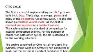
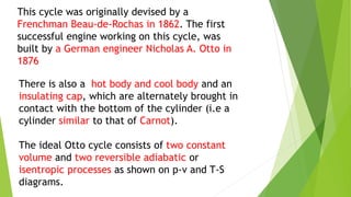
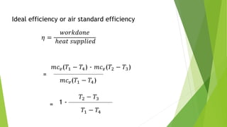
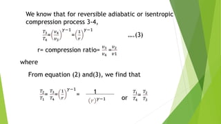
OTTO CYCLE
MAESH KUMAR P
2021017024
I B.Tech (EEE)
OTTO CYCLE
The first successful engine working on this "cycle was
built by A. Otto. These days, many gas, petrol and
many of the oil engines run on this cycle. It is the also
known as constant volume cycle, as the heat is
received and rejected at a constant volume.
This cycle is taken as a standard of comparison for
internal combustion engines. For the purpose of
comparison with other cycles, the air is assumed to
be the working substance.
The engine conceived by Otto has air enclosed in a
cylinder, whose walls are perfectly non-conductor of
This cycle was originally devised by a
Frenchman Beau-de-Rochas in 1862. The first
successful engine working on this cycle, was
built by a German engineer Nicholas A. Otto in
1876
There is also a hot body and cool body and an
insulating cap, which are alternately brought in
contact with the bottom of the cylinder (i.e a
cylinder similar to that of Carnot).
The ideal Otto cycle consists of two constant
volume and two reversible adiabatic or
isentropic processes as shown on p-v and T-S
diagrams.
STAGES
 1-2 reversible adiabatic or isentropic expansion
 2-3 constant volume cooling
 3-4 reversible adiabatic or isentrobic compression
 4-1 constant volume heating
1. REVERSIBLE ADIABATIC OR ISENTROPIC
EXPANSION
 The air is expanded reversibly and adiabatically
from initial temperature 𝑇1 to a temperature 𝑇2
as shown by the curve 1-2. In this process, no
heat is absorbed or rejected by the air.
2.CONSTANT VOLUME COOLING
 The air is cooled at constant volume from
temperature T₂ to a temperature 𝑇3 , as shown by
the curve 2-3 . We know that heat rejected by the
air during this process.
 𝑄2−3 = 𝑚𝑐𝑣(𝑇2 − 𝑇3)
3. REVERSIBLE ADIABATIC OR ISENTROPIC
COMPRESSION
 The air is compressed reversibly and adiabatically
from temperature 𝑇3to a temperature 𝑇4 as shown
in by the curve 3-4 . In this process, no heat is
absorbed or rejected by the air.
4.CONSTANT VOLUME HEATING
 The air is now heated at constant volume from
temperature 𝑇4 to a temperature 𝑇1 as shown by
the curve 4-1. We know that heat absorbed by the
air during this process.
 𝑄4−1 = 𝑚𝑐𝑣(𝑇1 − 𝑇4)
 We see that the air has been brought back to its
original conditions of pressure, volume and
temperature, thus completing the cycle.
 Work done= heat absorbed-heat rejected
= 𝑚𝑐𝑣(𝑇1 − 𝑇4) - 𝑚𝑐𝑣(𝑇2 − 𝑇3)
Ideal efficiency or air standard efficiency
𝜂 =
𝑤𝑜𝑟𝑘𝑑𝑜𝑛𝑒
ℎ𝑒𝑎𝑡 𝑠𝑢𝑝𝑝𝑙𝑖𝑒𝑑
=
𝑚𝑐𝑣(𝑇1 − 𝑇4) - 𝑚𝑐𝑣(𝑇2 − 𝑇3)
𝑚𝑐𝑣(𝑇1 − 𝑇4)
1 -
𝑇2 − 𝑇3
𝑇1 − 𝑇4
=
= 1- ….(1)
𝑇3
𝑇2
𝑇3
− 1
𝑇1
𝑇4
− 1
𝑇4
We know that for reversible adiabatic or isentropic
expansion process 1-2,
𝑇2
𝑇1
=
𝑣1
𝑣2
𝛾−1
=
1
𝑟
𝛾−1
…..(2)
r= compression ratio=
𝑣2
𝑣1
We know that for reversible adiabatic or isentropic
compression process 3-4,
𝑇3
𝑇4
=
𝑣4
𝑣3
𝛾−1
=
1
𝑟
𝛾−1
….(3)
r= compression ratio=
𝑣3
𝑣4
=
𝑣2
𝑣1
where
From equation (2) and(3), we find that
𝑇2
𝑇1
=
𝑇3
𝑇4
=
1
𝑟
𝛾−1
= 1
𝑟 𝛾−1 or
𝑇1
𝑇4
=
𝑇2
𝑇3
Substituting the value of
𝑇1
𝑇4
in equation(1)
Efficiency 𝜂= 1-
𝑇3
𝑇4
= 1-
𝑇2
𝑇1
=1-
1
𝑟 𝛾−1
Efficiency 𝜂= 1 - 1
r γ−1
……
𝑇3
𝑇4
=
𝑇2
𝑇1
…..(4)
OTTO CYCLE

OTTO CYCLE

  • 1.
    OTTO CYCLE MAESH KUMARP 2021017024 I B.Tech (EEE)
  • 2.
    OTTO CYCLE The firstsuccessful engine working on this "cycle was built by A. Otto. These days, many gas, petrol and many of the oil engines run on this cycle. It is the also known as constant volume cycle, as the heat is received and rejected at a constant volume. This cycle is taken as a standard of comparison for internal combustion engines. For the purpose of comparison with other cycles, the air is assumed to be the working substance. The engine conceived by Otto has air enclosed in a cylinder, whose walls are perfectly non-conductor of
  • 3.
    This cycle wasoriginally devised by a Frenchman Beau-de-Rochas in 1862. The first successful engine working on this cycle, was built by a German engineer Nicholas A. Otto in 1876 There is also a hot body and cool body and an insulating cap, which are alternately brought in contact with the bottom of the cylinder (i.e a cylinder similar to that of Carnot). The ideal Otto cycle consists of two constant volume and two reversible adiabatic or isentropic processes as shown on p-v and T-S diagrams.
  • 4.
    STAGES  1-2 reversibleadiabatic or isentropic expansion  2-3 constant volume cooling  3-4 reversible adiabatic or isentrobic compression  4-1 constant volume heating
  • 6.
    1. REVERSIBLE ADIABATICOR ISENTROPIC EXPANSION  The air is expanded reversibly and adiabatically from initial temperature 𝑇1 to a temperature 𝑇2 as shown by the curve 1-2. In this process, no heat is absorbed or rejected by the air.
  • 7.
    2.CONSTANT VOLUME COOLING The air is cooled at constant volume from temperature T₂ to a temperature 𝑇3 , as shown by the curve 2-3 . We know that heat rejected by the air during this process.  𝑄2−3 = 𝑚𝑐𝑣(𝑇2 − 𝑇3)
  • 8.
    3. REVERSIBLE ADIABATICOR ISENTROPIC COMPRESSION  The air is compressed reversibly and adiabatically from temperature 𝑇3to a temperature 𝑇4 as shown in by the curve 3-4 . In this process, no heat is absorbed or rejected by the air.
  • 9.
    4.CONSTANT VOLUME HEATING The air is now heated at constant volume from temperature 𝑇4 to a temperature 𝑇1 as shown by the curve 4-1. We know that heat absorbed by the air during this process.  𝑄4−1 = 𝑚𝑐𝑣(𝑇1 − 𝑇4)  We see that the air has been brought back to its original conditions of pressure, volume and temperature, thus completing the cycle.  Work done= heat absorbed-heat rejected = 𝑚𝑐𝑣(𝑇1 − 𝑇4) - 𝑚𝑐𝑣(𝑇2 − 𝑇3)
  • 10.
    Ideal efficiency orair standard efficiency 𝜂 = 𝑤𝑜𝑟𝑘𝑑𝑜𝑛𝑒 ℎ𝑒𝑎𝑡 𝑠𝑢𝑝𝑝𝑙𝑖𝑒𝑑 = 𝑚𝑐𝑣(𝑇1 − 𝑇4) - 𝑚𝑐𝑣(𝑇2 − 𝑇3) 𝑚𝑐𝑣(𝑇1 − 𝑇4) 1 - 𝑇2 − 𝑇3 𝑇1 − 𝑇4 =
  • 11.
    = 1- ….(1) 𝑇3 𝑇2 𝑇3 −1 𝑇1 𝑇4 − 1 𝑇4 We know that for reversible adiabatic or isentropic expansion process 1-2, 𝑇2 𝑇1 = 𝑣1 𝑣2 𝛾−1 = 1 𝑟 𝛾−1 …..(2) r= compression ratio= 𝑣2 𝑣1
  • 12.
    We know thatfor reversible adiabatic or isentropic compression process 3-4, 𝑇3 𝑇4 = 𝑣4 𝑣3 𝛾−1 = 1 𝑟 𝛾−1 ….(3) r= compression ratio= 𝑣3 𝑣4 = 𝑣2 𝑣1 where From equation (2) and(3), we find that 𝑇2 𝑇1 = 𝑇3 𝑇4 = 1 𝑟 𝛾−1 = 1 𝑟 𝛾−1 or 𝑇1 𝑇4 = 𝑇2 𝑇3
  • 13.
    Substituting the valueof 𝑇1 𝑇4 in equation(1) Efficiency 𝜂= 1- 𝑇3 𝑇4 = 1- 𝑇2 𝑇1 =1- 1 𝑟 𝛾−1 Efficiency 𝜂= 1 - 1 r γ−1 …… 𝑇3 𝑇4 = 𝑇2 𝑇1 …..(4)