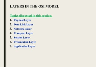
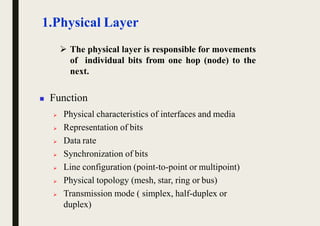
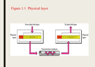
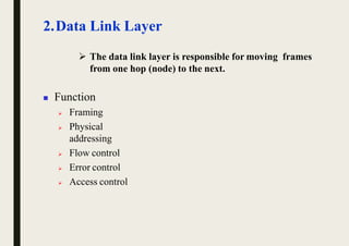
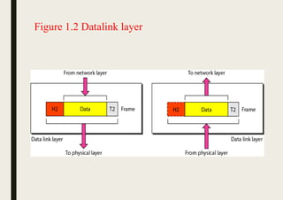
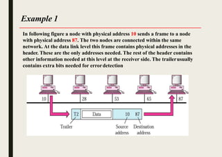
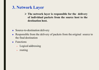
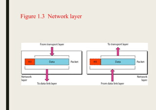
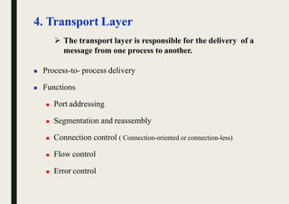
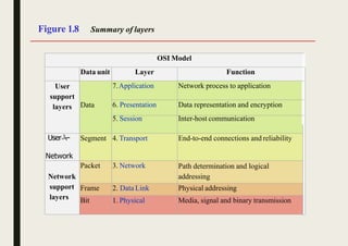
OSI MODEL
Presented by
N.Prakash
Assistant Professor
Department Of ECE
KIT-KalaignarKarunanidhi institute of Technology
INTRODUCTION
 Established in 1947, the International
Standards Organization (ISO) is a
multinational body dedicated to worldwide
agreement on international standards.
 An ISO is the Open Systems Interconnection
(OSI) model is the standard that covers all
aspects of network communications from ISO.
It was first introduced in the late 1970s.
LAYERS IN THE OSI MODEL
Topics discussed in this section:
1. Physical Layer
2. Data Link Layer
3. Network Layer
4. Transport Layer
5. Session Layer
6. Presentation Layer
7. Application Layer
1.Physical Layer
 The physical layer is responsible for movements
of individual bits from one hop (node) to the
next.
 Function
 Physical characteristics of interfaces and media
 Representation of bits
 Data rate
 Synchronization of bits
 Line configuration (point-to-point or multipoint)
 Physical topology (mesh, star, ring or bus)
 Transmission mode ( simplex, half-duplex or
duplex)
Figure 1.1 Physical layer
 The data link layer is responsible for moving frames
from one hop (node) to the next.
2.Data Link Layer
 Function
 Framing
 Physical
addressing
 Flow control
 Error control
 Access control
Figure 1.2 Datalink layer
Example 1
In following figure a node with physical address 10 sends a frame to a node
with physical address 87. The two nodes are connected within the same
network. At the data link level this frame contains physical addresses in the
header. These are the only addresses needed. The rest of the header contains
other information needed at this level at the receiver side. The trailerusually
contains extra bits needed for errordetection
3. Network Layer
 The network layer is responsible for the delivery
of individual packets from the source host to the
destination host.
 Source-to-destination delivery
 Responsible from the delivery of packets from the original source to
the final destination
 Functions
 Logical addressing
 routing
Figure 1.3 Network layer
Example 2
We want to send data from a node
with network address A and
physical address 10, located on
one LAN, to a node with a
network address P and physical
address 95, located on another
LAN. Because the two devices are
located on different networks, we
cannot use physical addresses
only; the physical addresses only
have local influence. What we
need here are universal addresses
that can pass through the LAN
boundaries. The network
addresses have this characteristic.
4. Transport Layer
 The transport layer is responsible for the delivery of a
message from one process to another.
 Process-to- process delivery
 Functions
 Port addressing
 Segmentation and reassembly
 Connection control ( Connection-oriented or connection-less)
 Flow control
 Error control
Figure 1.4 Transport layer
Example 3
Following Figure shows an example of transport layer communication. Data coming
from the upper layers have port addresses j and k (j is the address of the sending
process, and k is the address of the receiving process). Since the data size is larger
than the network layer can handle, the data are split into two packets, each packet
retaining the port addresses (j and k). Then in the network layer, network addresses
(A and P) are added to each packet.
SourceA Destination P
5.Session Layer
 The session layer is responsible for dialog control
and synchronization.
 It establishes, maintains and synchronize the interaction
between communicating system
 Function
 Dialog control
 Synchronization (checkpoints)
Figure 1.5 Session layer
6.Presentation Layer
 The presentation layer is responsible for translation,
compression, and encryption.
 Concerned with the syntax and semantics of the
information exchanged between two system
 Functions
 Translation ( EBCDIC-coded text file  ASCII-coded file)
 Encryption and Decryption
 Compression
Figure 1.6 Presentation layer
7. Application Layer
 The application layer is responsible for providing
services to the user.
 Functions
 Network virtual terminal (Remote log-in)
 File transfer and access
 Mail services
 Directory services (Distributed Database)
 Accessing the World Wide Web
Figure 1.7 Application layer
Figure 1.8 Summary of layers
OSI Model
Data unit Layer Function
User
support
layers Data
7.Application Network process to application
6. Presentation Data representation and encryption
5. Session Inter-host communication
User
Network
Segment 4. Transport End-to-end connections and reliability
Network
support
layers
Packet 3. Network Path determination and logical
addressing
Frame 2. Data Link Physical addressing
Bit 1. Physical Media, signal and binary transmission
THANK YOU

Osi model

  • 1.
    OSI MODEL Presented by N.Prakash AssistantProfessor Department Of ECE KIT-KalaignarKarunanidhi institute of Technology
  • 2.
    INTRODUCTION  Established in1947, the International Standards Organization (ISO) is a multinational body dedicated to worldwide agreement on international standards.  An ISO is the Open Systems Interconnection (OSI) model is the standard that covers all aspects of network communications from ISO. It was first introduced in the late 1970s.
  • 3.
    LAYERS IN THEOSI MODEL Topics discussed in this section: 1. Physical Layer 2. Data Link Layer 3. Network Layer 4. Transport Layer 5. Session Layer 6. Presentation Layer 7. Application Layer
  • 4.
    1.Physical Layer  Thephysical layer is responsible for movements of individual bits from one hop (node) to the next.  Function  Physical characteristics of interfaces and media  Representation of bits  Data rate  Synchronization of bits  Line configuration (point-to-point or multipoint)  Physical topology (mesh, star, ring or bus)  Transmission mode ( simplex, half-duplex or duplex)
  • 5.
  • 6.
     The datalink layer is responsible for moving frames from one hop (node) to the next. 2.Data Link Layer  Function  Framing  Physical addressing  Flow control  Error control  Access control
  • 7.
  • 8.
    Example 1 In followingfigure a node with physical address 10 sends a frame to a node with physical address 87. The two nodes are connected within the same network. At the data link level this frame contains physical addresses in the header. These are the only addresses needed. The rest of the header contains other information needed at this level at the receiver side. The trailerusually contains extra bits needed for errordetection
  • 9.
    3. Network Layer The network layer is responsible for the delivery of individual packets from the source host to the destination host.  Source-to-destination delivery  Responsible from the delivery of packets from the original source to the final destination  Functions  Logical addressing  routing
  • 10.
  • 11.
    Example 2 We wantto send data from a node with network address A and physical address 10, located on one LAN, to a node with a network address P and physical address 95, located on another LAN. Because the two devices are located on different networks, we cannot use physical addresses only; the physical addresses only have local influence. What we need here are universal addresses that can pass through the LAN boundaries. The network addresses have this characteristic.
  • 12.
    4. Transport Layer The transport layer is responsible for the delivery of a message from one process to another.  Process-to- process delivery  Functions  Port addressing  Segmentation and reassembly  Connection control ( Connection-oriented or connection-less)  Flow control  Error control
  • 13.
  • 14.
    Example 3 Following Figureshows an example of transport layer communication. Data coming from the upper layers have port addresses j and k (j is the address of the sending process, and k is the address of the receiving process). Since the data size is larger than the network layer can handle, the data are split into two packets, each packet retaining the port addresses (j and k). Then in the network layer, network addresses (A and P) are added to each packet. SourceA Destination P
  • 15.
    5.Session Layer  Thesession layer is responsible for dialog control and synchronization.  It establishes, maintains and synchronize the interaction between communicating system  Function  Dialog control  Synchronization (checkpoints)
  • 16.
  • 17.
    6.Presentation Layer  Thepresentation layer is responsible for translation, compression, and encryption.  Concerned with the syntax and semantics of the information exchanged between two system  Functions  Translation ( EBCDIC-coded text file  ASCII-coded file)  Encryption and Decryption  Compression
  • 18.
  • 19.
    7. Application Layer The application layer is responsible for providing services to the user.  Functions  Network virtual terminal (Remote log-in)  File transfer and access  Mail services  Directory services (Distributed Database)  Accessing the World Wide Web
  • 20.
  • 21.
    Figure 1.8 Summaryof layers OSI Model Data unit Layer Function User support layers Data 7.Application Network process to application 6. Presentation Data representation and encryption 5. Session Inter-host communication User Network Segment 4. Transport End-to-end connections and reliability Network support layers Packet 3. Network Path determination and logical addressing Frame 2. Data Link Physical addressing Bit 1. Physical Media, signal and binary transmission
  • 22.