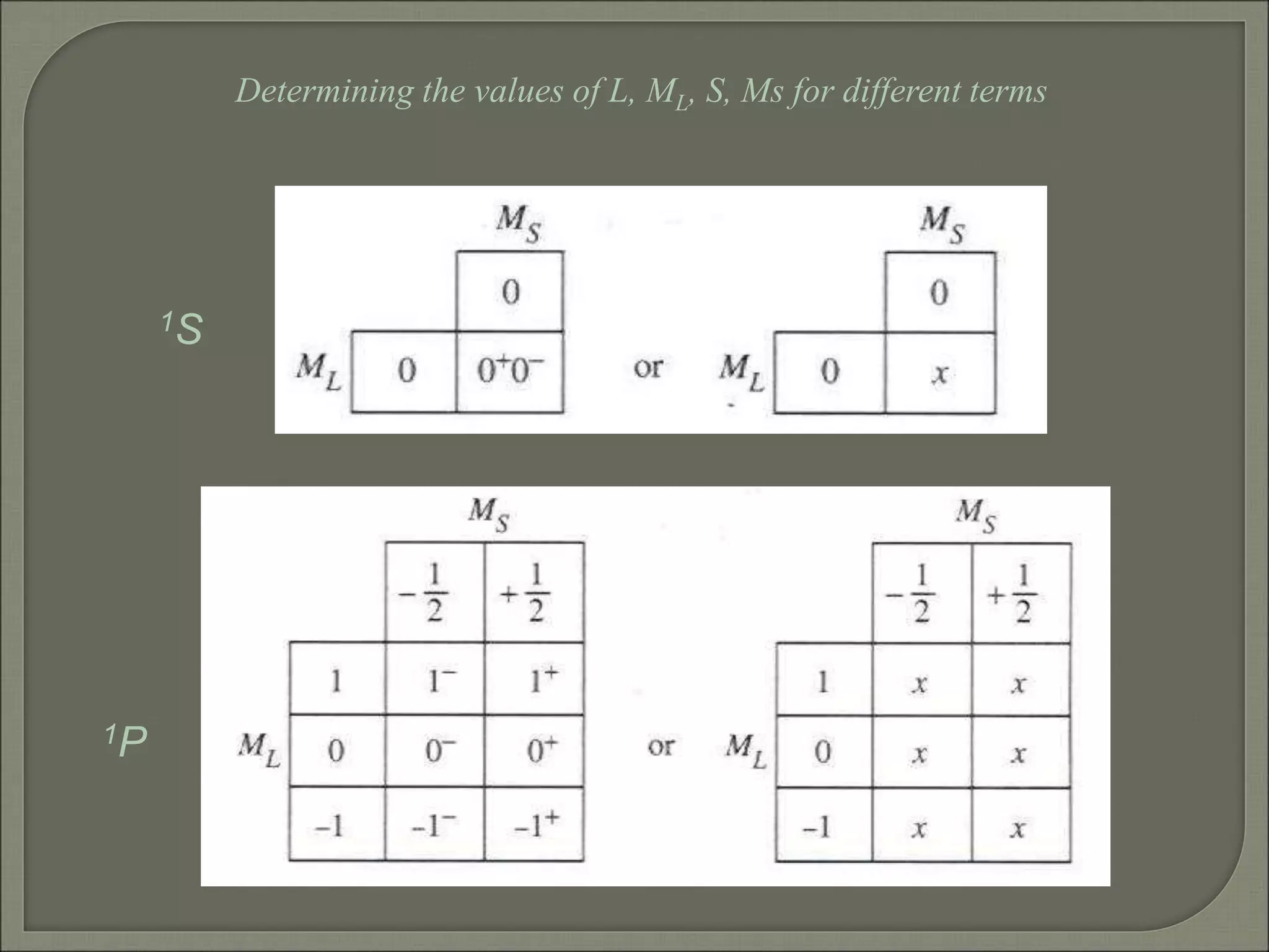
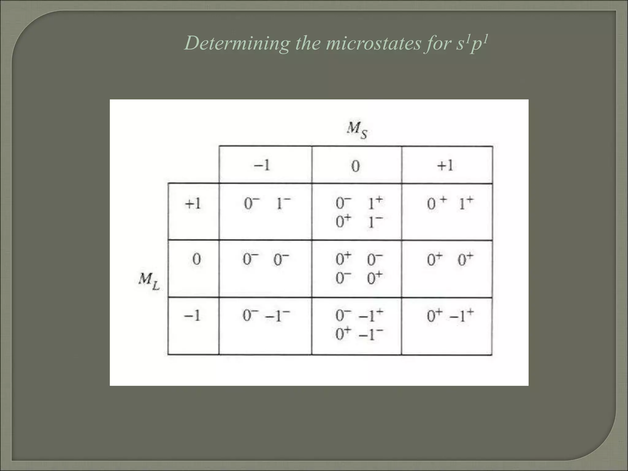
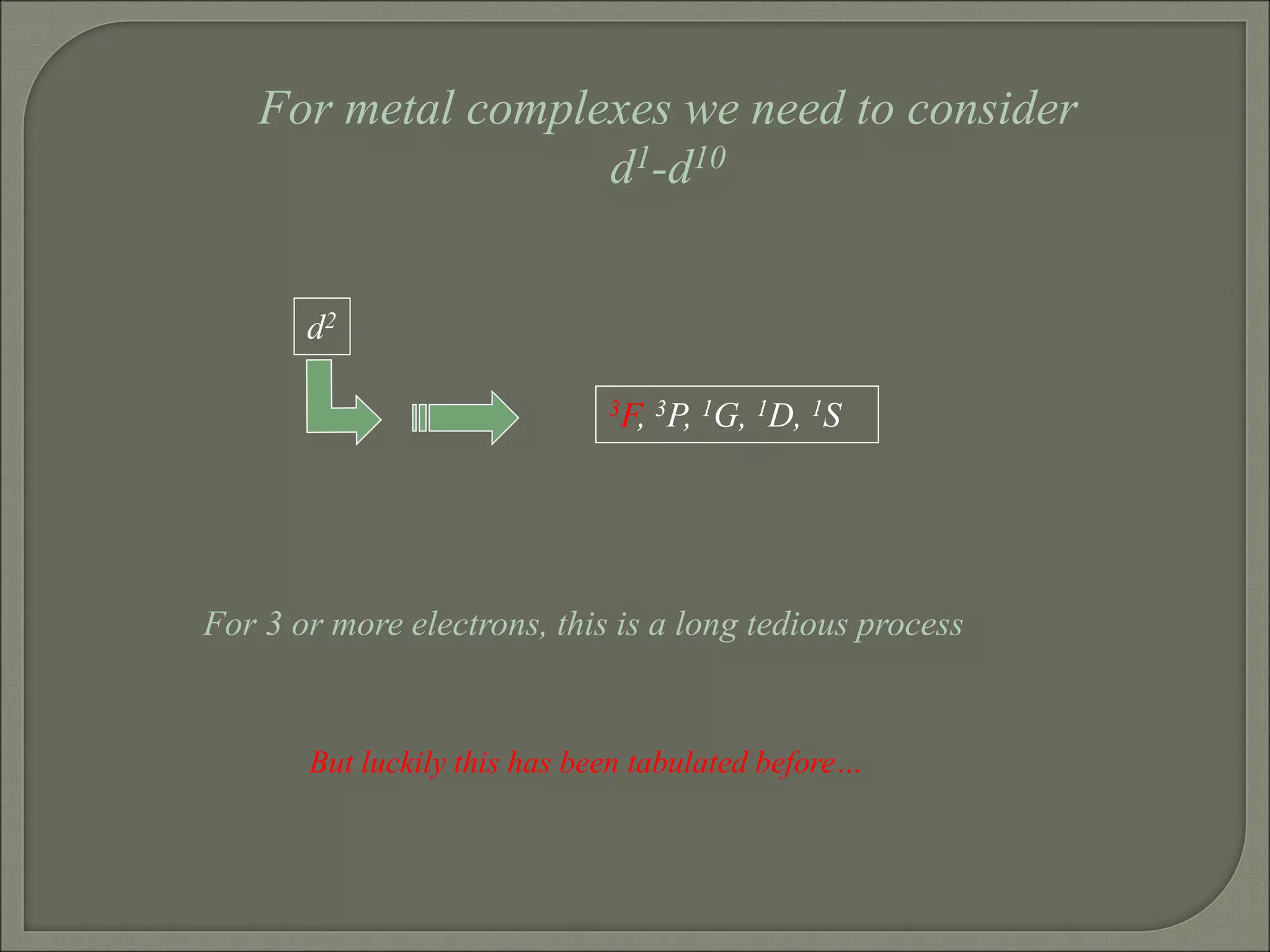
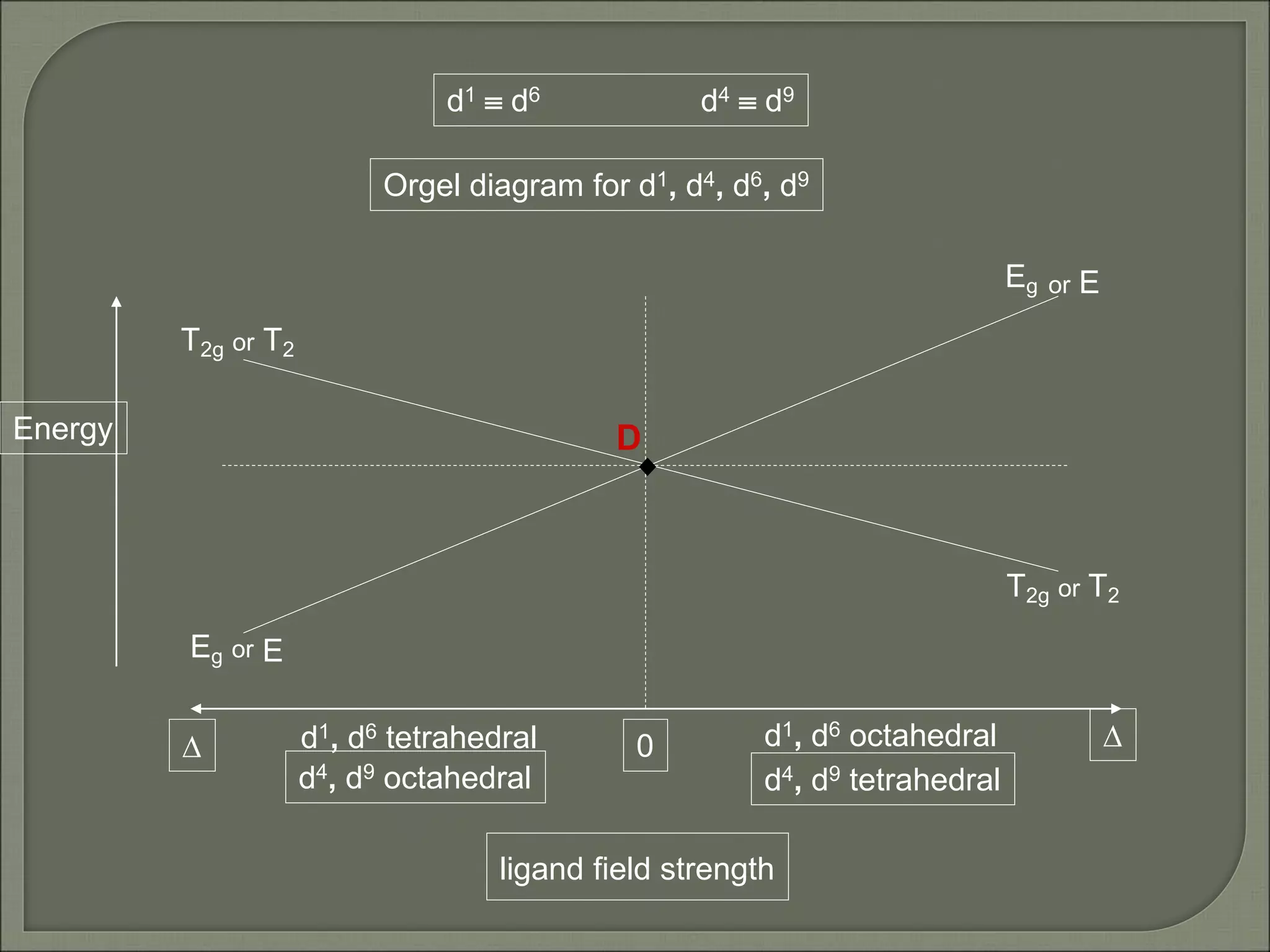
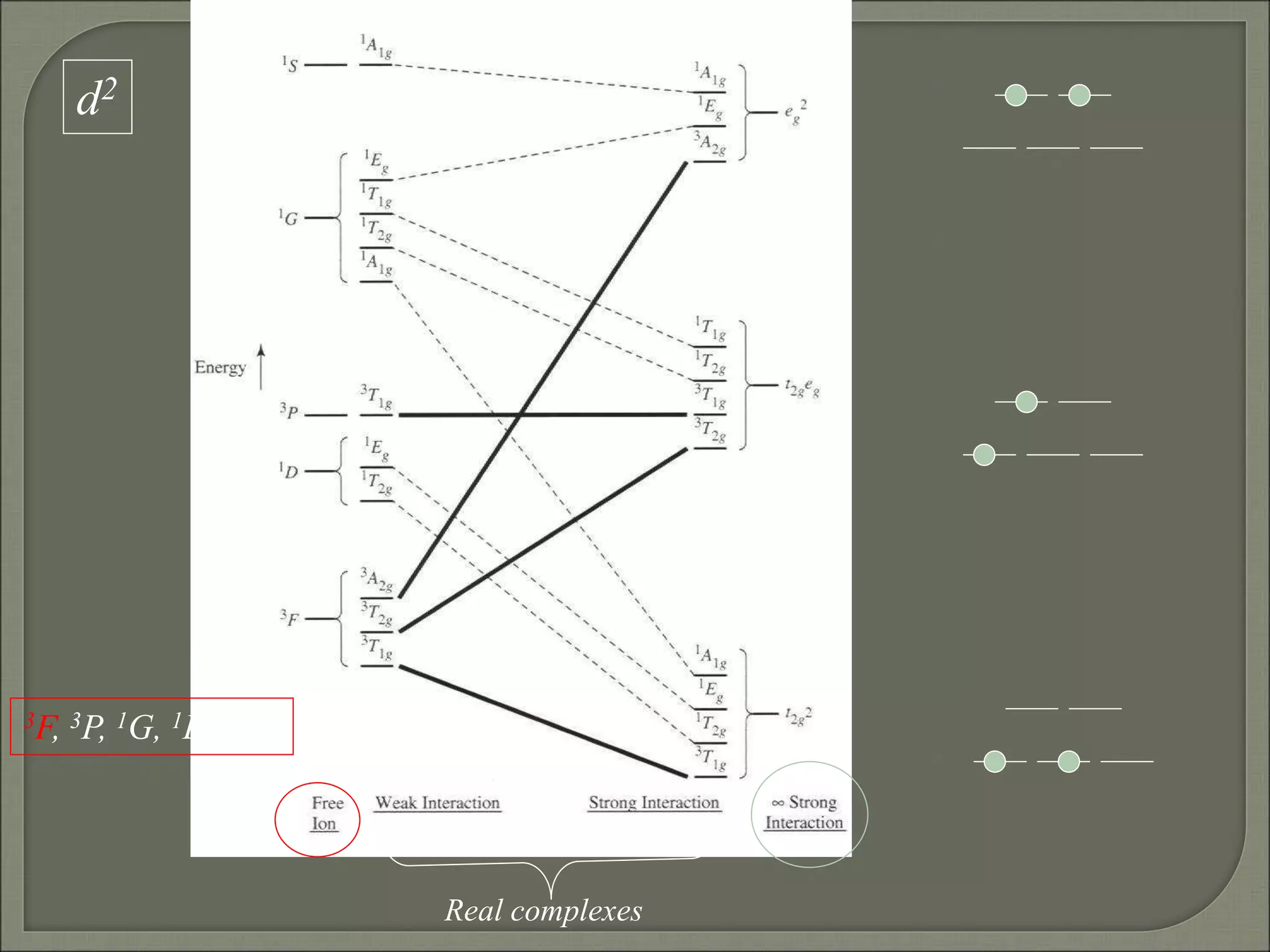
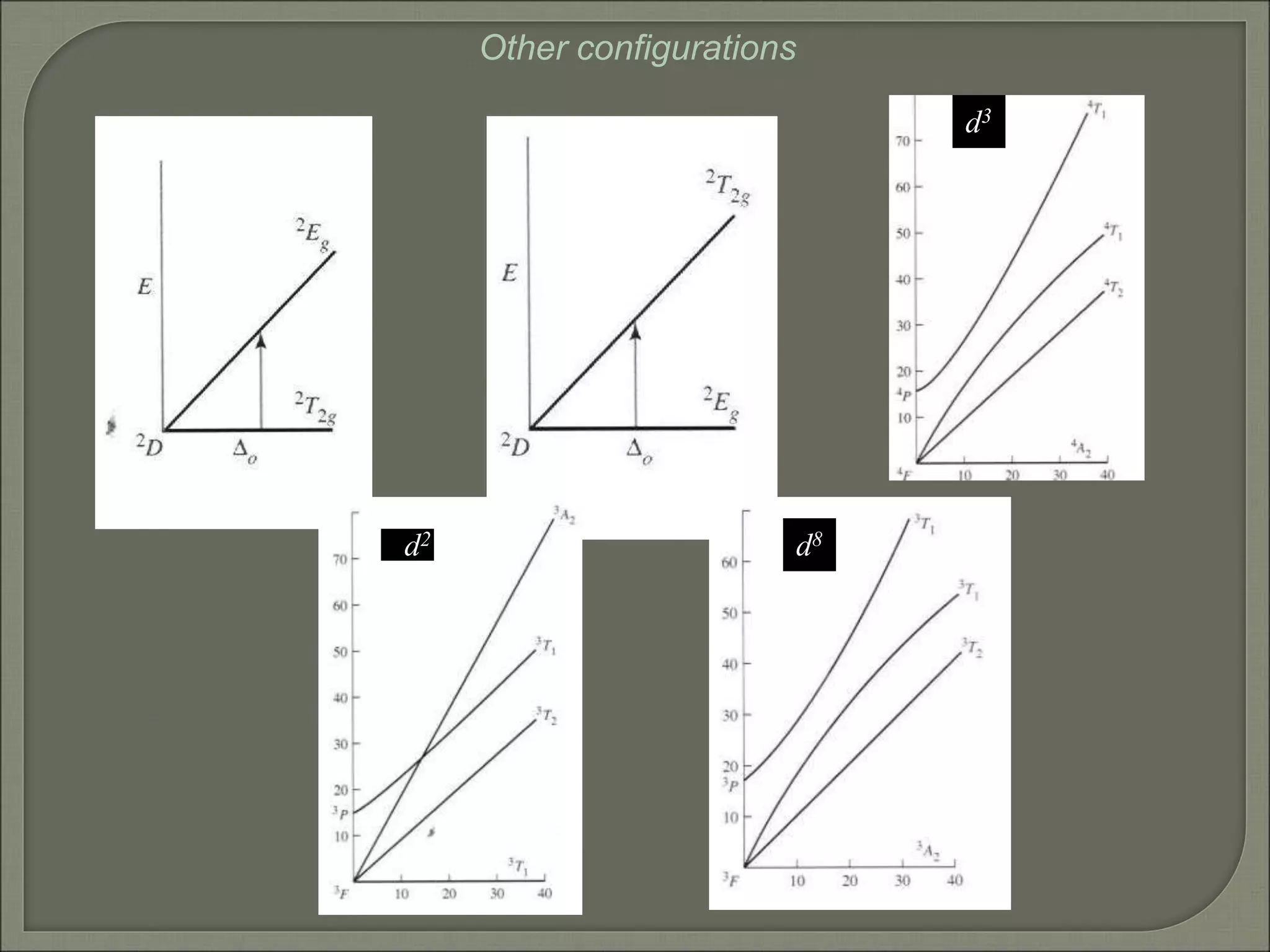
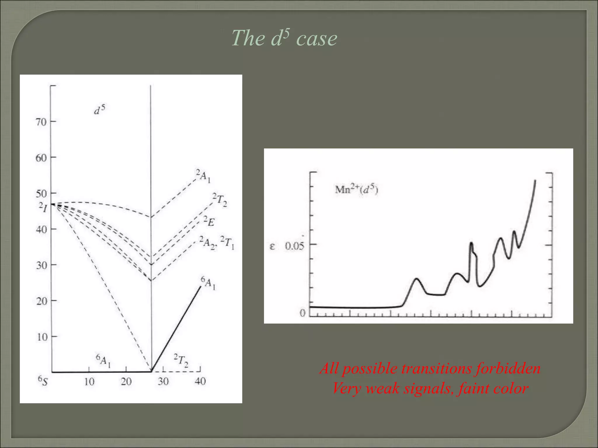
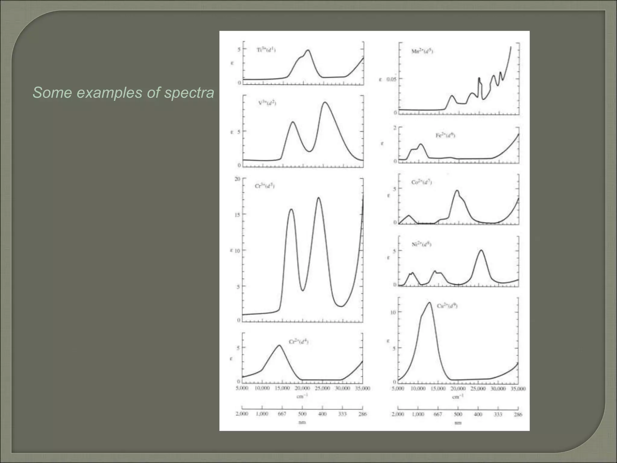
SARAH TUCKER COLLEGE
TIRUNELVELI.
6 s ligands x 2e each
12 s bonding e
“ligand character”
“d0-d10 electrons”
non bonding
anti bonding
“metal character”
ML6 s-only bonding
The bonding orbitals, essentially the ligand lone pairs,
will not be worked with further.
t2g
eg
t2g
ML6
s-only
ML6
s + π
Stabilization
(empty π-orbitals on ligands)
Do
D’o
Do has increased
π-bonding may be introduced
as a perturbation of the t2g/eg set:
Case 1 (CN-, CO, C2H4)
empty π-orbitals on the ligands
ML π-bonding (π-back bonding)
t2g (π)
t2g (π*)
eg
These are the SALC
formed from the p
orbitals of the ligands
that can interac with
the d on the metal.
t2g
eg
t2g
ML6
s-only
ML6
s + π
π-bonding may be introduced
as a perturbation of the t2g/eg set.
Case 2 (Cl-, F-)
filled π-orbitals on the ligands
LM π-bonding
(filled π-orbitals)
Stabilization
Destabilization
t2g (π)
t2g (π*)
eg
D’o
Do
Do has decreased
Strong field / low spin Weak field / high spin
Putting it all on one
diagram.
Purely s ligands:
D: en > NH3 (order of proton basicity)
 donating which decreases splitting and causes high spin:
D: H2O > F > RCO2 > OH > Cl > Br > I (also proton basicity)
 accepting ligands increase splitting and may be low spin
D: CO, CN-, > phenanthroline > NO2
- > NCS-
CO, CN- > phen > en > NH3 > NCS- > H2O > F- > RCO2
- > OH- > Cl- > Br- > I-
Strong field,
 acceptors
large D
low spin
s only
Weak field,
 donors
small D
high spin
y
x
z
Most convenient to use a local coordinate
system on each ligand with
y pointing in towards the metal. py to be used
for s bonding.
z being perpendicular to the molecular plane. pz
to be used for  bonding perpendicular to the
plane, ^.
x lying in the molecular plane. px to be used
for  bonding in the molecular plane, |.
ML4 square planar complexes
ligand group orbitals and matching metal orbitals
s bonding
 bonding (in)
 bonding
(perp)
ML4 square planar complexes
MO diagram
s-only bonding Sample -
bonding
eg
An attempt to systematize the interactions for all geometries.
M
1
6
5
4
2
3
M
10
9
7
8
M 2
6
1
12
11
The various complexes may be fashioned out of the ligands
above
Linear: 1,6
Trigonal: 2,11,12
T-shape: 1,3,5
Tetrahedral: 7,8,9,10
Square planar: 2,3,4,5
Trigonal bipyramid: 1,2,6,11,12
Square pyramid: 1,2,3,4,5
Octahedral: 1,2,3,4,5,6
All s interactions with the ligands are stabilizing to the
ligands and destabilizing to the d orbitals. The interaction of a
ligand with a d orbital depends on their orientation with
respect to each other, estimated by their overlap which can be
calculated.
The total destabilization of a d orbital comes from all the
interactions with the set of ligands.
For any particular complex geometry we can obtain the
overlaps of a particular d orbital with all the various ligands
and thus the destabilization.
ligand dz2 dx2-y2
dxy dxz dyz
1 1 es 0 0 0 0
2 ¼ ¾ 0 0 0
3 ¼ ¾ 0 0 0
4 ¼ ¾ 0 0 0
5 ¼ ¾ 0 0 0
6 1 0 0 0 0
7 0 0 1/3 1/3 1/3
8 0 0 1/3 1/3 1/3
9 0 0 1/3 1/3 1/3
10 0 0 1/3 1/3 1/3
11 ¼ 3/16 9/16 0 0
12 1/4 3/16 9/16 0 0
Thus, for example a dx2-y2 orbital is destabilized by (3/4 +6/16) es
= 18/16 es in a trigonal bipyramid complex due to s interaction.
The dxy, equivalent by symmetry, is destabilized by the same
amount. The dz2 is destabililzed by 11/4 es.
Coordination Chemistry
Electronic Spectra of Metal Complexes
Electronic spectra (UV-vis spectroscopy)
DE
hn
The colors of metal complexes
Electronic configurations of multi-electron atoms
What is a 2p2 configuration?
n = 2; l = 1; ml = -1, 0, +1; ms = ± 1/2
Many configurations fit that description
These configurations are called microstates
and they have different energies
because of inter-electronic repulsions
Electronic configurations of multi-electron atoms
Russell-Saunders (or LS) coupling
For each 2p electron
n = 1; l = 1
ml = -1, 0, +1
ms = ± 1/2
For the multi-electron atom
L = total orbital angular momentum quantum number
S = total spin angular momentum quantum number
Spin multiplicity = 2S+1
ML = ∑ml (-L,…0,…+L)
MS = ∑ms (S, S-1, …,0,…-S)
ML/MS define microstates and L/S define
states (collections of microstates)
Groups of microstates with the same
energy are called terms
Determining the microstates for p2
Spin multiplicity 2S + 1
Determining the values of L, ML, S, Ms for different terms
1S
1P
Classifying the microstates for p2
Spin multiplicity = # columns of microstates
Next largest ML is +1,
so L = 1 (a P term)
and MS = 0, ±1/2 for ML = +1,
2S +1 = 3
3P
One remaining microstate
ML is 0, L = 0 (an S term)
and MS = 0 for ML = 0,
2S +1 = 1
1S
Largest ML is +2,
so L = 2 (a D term)
and MS = 0 for ML = +2,
2S +1 = 1 (S = 0)
1D
Largest ML is +2,
so L = 2 (a D term)
and MS = 0 for ML = +2,
2S +1 = 1 (S = 0)
1D
Next largest ML is +1,
so L = 1 (a P term)
and MS = 0, ±1/2 for ML = +1,
2S +1 = 3
3P
ML is 0, L = 0
2S +1 = 1
1S
Energy of terms (Hund’s rules)
Lowest energy (ground term)
Highest spin multiplicity
3P term for p2 case
If two states have
the same maximum spin multiplicity
Ground term is that of highest L
3P has S = 1, L = 1
Determining the microstates for s1p1
Determining the terms for s1p1
Ground-state term
Coordination Chemistry
Electronic Spectra of Metal Complexes
cont.
Electronic configurations of multi-electron atoms
Russell-Saunders (or LS) coupling
For each 2p electron
n = 1; l = 1
ml = -1, 0, +1
ms = ± 1/2
For the multi-electron atom
L = total orbital angular momentum quantum number
S = total spin angular momentum quantum number
Spin multiplicity = 2S+1
ML = ∑ml (-L,…0,…+L)
MS = ∑ms (S, S-1, …,0,…-S)
ML/MS define microstates and L/S define
states (collections of microstates)
Groups of microstates with the same
energy are called terms
before we did:
p2
ML & MS
Microstate
Table
States (S, P, D)
Spin multiplicity
Terms
3P, 1D, 1S
Ground state term
3P
For metal complexes we need to consider
d1-d10
d2
3F, 3P, 1G, 1D, 1S
For 3 or more electrons, this is a long tedious process
But luckily this has been tabulated before…
Transitions between electronic terms will give rise to spectra
Selection rules
(determine intensities)
Laporte rule
g  g forbidden (that is, d-d forbidden)
but g  u allowed (that is, d-p allowed)
Spin rule
Transitions between states of different multiplicities forbidden
Transitions between states of same multiplicities allowed
These rules are relaxed by molecular vibrations, and spin-orbit coupling
Group theory analysis of term splitting
dn Free ion GS Oct. complex Tet complex
d0 1S t2g
0eg
0 e0t2
0
d1 2D t2g
1eg
0 e1t2
0
d2 3F t2g
2eg
0 e2t2
0
d3 4F t2g
3eg
0 e2t2
1
d4 5D t2g
3eg
1 e2t2
2
d5 6S t2g
3eg
2 e2t2
3
d6 5D t2g
4eg
2 e3t2
3
d7 4F t2g
5eg
2 e4t2
3
d8 3F t2g
6eg
2 e4t2
4
d9 2D t2g
6eg
3 e4t2
5
d10 1S t2g
6eg
4 e4t2
6
Holes: dn = d10-n and neglecting spin dn = d5+n; same
splitting but reversed energies because positive.
A t2 hole in d5,
reversed energies,
reversed again
relative to
octahedral since tet.
Holes in d5
and d10,
reversing
energies
relative to
d1
An e electron
superimposed
on a spherical
distribution
energies
reversed
because
tetrahedral
Expect oct d1 and d6 to behave same as tet d4 and d9
Expect oct d4 and d9 (holes), tet d1 and d6 to be reverse of oct d1
Energy
ligand field strength
d1  d6 d4  d9
Orgel diagram for d1, d4, d6, d9
0 D
D
D
d4, d9 tetrahedral
or T2
or E
T2g or
Eg or
d4, d9 octahedral
T2
E
d1, d6 tetrahedral
Eg
T2g
d1, d6 octahedral
F
P
Ligand field strength (Dq)
Energy
Orgel diagram for d2, d3, d7, d8 ions
d2, d7 tetrahedral d2, d7 octahedral
d3, d8 octahedral d3, d8 tetrahedral
0
A2 or A2g
T1 or T1g
T2 or T2g
A2 or A2g
T2 or T2g
T1 or T1g
T1 or T1g
T1 or T1g
d2
3F, 3P, 1G, 1D, 1S
Real complexes
Tanabe-Sugano diagrams
Electronic transitions and spectra
Other configurations
d1 d9
d3
d2 d8
d3
Other configurations
The limit between
high spin and low spin
Determining Do from spectra
d1
d9
One transition allowed of energy Do
Lowest energy transition = Do
mixing
mixing
Determining Do from spectra
Ground state is mixing
E (T1gA2g) - E (T1gT2g) = Do
The d5 case
All possible transitions forbidden
Very weak signals, faint color
Some examples of spectra
Charge transfer spectra
LMCT
MLCT
Ligand character
Metal character
Metal character
Ligand character
Much more intense bands
Orgel diagram

Orgel diagram

  • 1.
  • 2.
    6 s ligandsx 2e each 12 s bonding e “ligand character” “d0-d10 electrons” non bonding anti bonding “metal character” ML6 s-only bonding The bonding orbitals, essentially the ligand lone pairs, will not be worked with further.
  • 3.
    t2g eg t2g ML6 s-only ML6 s + π Stabilization (emptyπ-orbitals on ligands) Do D’o Do has increased π-bonding may be introduced as a perturbation of the t2g/eg set: Case 1 (CN-, CO, C2H4) empty π-orbitals on the ligands ML π-bonding (π-back bonding) t2g (π) t2g (π*) eg These are the SALC formed from the p orbitals of the ligands that can interac with the d on the metal.
  • 4.
    t2g eg t2g ML6 s-only ML6 s + π π-bondingmay be introduced as a perturbation of the t2g/eg set. Case 2 (Cl-, F-) filled π-orbitals on the ligands LM π-bonding (filled π-orbitals) Stabilization Destabilization t2g (π) t2g (π*) eg D’o Do Do has decreased
  • 5.
    Strong field /low spin Weak field / high spin Putting it all on one diagram.
  • 6.
    Purely s ligands: D:en > NH3 (order of proton basicity)  donating which decreases splitting and causes high spin: D: H2O > F > RCO2 > OH > Cl > Br > I (also proton basicity)  accepting ligands increase splitting and may be low spin D: CO, CN-, > phenanthroline > NO2 - > NCS-
  • 7.
    CO, CN- >phen > en > NH3 > NCS- > H2O > F- > RCO2 - > OH- > Cl- > Br- > I- Strong field,  acceptors large D low spin s only Weak field,  donors small D high spin
  • 8.
    y x z Most convenient touse a local coordinate system on each ligand with y pointing in towards the metal. py to be used for s bonding. z being perpendicular to the molecular plane. pz to be used for  bonding perpendicular to the plane, ^. x lying in the molecular plane. px to be used for  bonding in the molecular plane, |.
  • 9.
    ML4 square planarcomplexes ligand group orbitals and matching metal orbitals s bonding  bonding (in)  bonding (perp)
  • 10.
    ML4 square planarcomplexes MO diagram s-only bonding Sample - bonding eg
  • 11.
    An attempt tosystematize the interactions for all geometries. M 1 6 5 4 2 3 M 10 9 7 8 M 2 6 1 12 11 The various complexes may be fashioned out of the ligands above Linear: 1,6 Trigonal: 2,11,12 T-shape: 1,3,5 Tetrahedral: 7,8,9,10 Square planar: 2,3,4,5 Trigonal bipyramid: 1,2,6,11,12 Square pyramid: 1,2,3,4,5 Octahedral: 1,2,3,4,5,6
  • 12.
    All s interactionswith the ligands are stabilizing to the ligands and destabilizing to the d orbitals. The interaction of a ligand with a d orbital depends on their orientation with respect to each other, estimated by their overlap which can be calculated. The total destabilization of a d orbital comes from all the interactions with the set of ligands. For any particular complex geometry we can obtain the overlaps of a particular d orbital with all the various ligands and thus the destabilization.
  • 13.
    ligand dz2 dx2-y2 dxydxz dyz 1 1 es 0 0 0 0 2 ¼ ¾ 0 0 0 3 ¼ ¾ 0 0 0 4 ¼ ¾ 0 0 0 5 ¼ ¾ 0 0 0 6 1 0 0 0 0 7 0 0 1/3 1/3 1/3 8 0 0 1/3 1/3 1/3 9 0 0 1/3 1/3 1/3 10 0 0 1/3 1/3 1/3 11 ¼ 3/16 9/16 0 0 12 1/4 3/16 9/16 0 0 Thus, for example a dx2-y2 orbital is destabilized by (3/4 +6/16) es = 18/16 es in a trigonal bipyramid complex due to s interaction. The dxy, equivalent by symmetry, is destabilized by the same amount. The dz2 is destabililzed by 11/4 es.
  • 14.
  • 15.
  • 16.
    Electronic spectra (UV-visspectroscopy) DE hn
  • 17.
    The colors ofmetal complexes
  • 19.
    Electronic configurations ofmulti-electron atoms What is a 2p2 configuration? n = 2; l = 1; ml = -1, 0, +1; ms = ± 1/2 Many configurations fit that description These configurations are called microstates and they have different energies because of inter-electronic repulsions
  • 20.
    Electronic configurations ofmulti-electron atoms Russell-Saunders (or LS) coupling For each 2p electron n = 1; l = 1 ml = -1, 0, +1 ms = ± 1/2 For the multi-electron atom L = total orbital angular momentum quantum number S = total spin angular momentum quantum number Spin multiplicity = 2S+1 ML = ∑ml (-L,…0,…+L) MS = ∑ms (S, S-1, …,0,…-S) ML/MS define microstates and L/S define states (collections of microstates) Groups of microstates with the same energy are called terms
  • 21.
  • 22.
  • 23.
    Determining the valuesof L, ML, S, Ms for different terms 1S 1P
  • 24.
    Classifying the microstatesfor p2 Spin multiplicity = # columns of microstates Next largest ML is +1, so L = 1 (a P term) and MS = 0, ±1/2 for ML = +1, 2S +1 = 3 3P One remaining microstate ML is 0, L = 0 (an S term) and MS = 0 for ML = 0, 2S +1 = 1 1S Largest ML is +2, so L = 2 (a D term) and MS = 0 for ML = +2, 2S +1 = 1 (S = 0) 1D
  • 25.
    Largest ML is+2, so L = 2 (a D term) and MS = 0 for ML = +2, 2S +1 = 1 (S = 0) 1D Next largest ML is +1, so L = 1 (a P term) and MS = 0, ±1/2 for ML = +1, 2S +1 = 3 3P ML is 0, L = 0 2S +1 = 1 1S
  • 26.
    Energy of terms(Hund’s rules) Lowest energy (ground term) Highest spin multiplicity 3P term for p2 case If two states have the same maximum spin multiplicity Ground term is that of highest L 3P has S = 1, L = 1
  • 27.
  • 28.
    Determining the termsfor s1p1 Ground-state term
  • 29.
  • 30.
    Electronic configurations ofmulti-electron atoms Russell-Saunders (or LS) coupling For each 2p electron n = 1; l = 1 ml = -1, 0, +1 ms = ± 1/2 For the multi-electron atom L = total orbital angular momentum quantum number S = total spin angular momentum quantum number Spin multiplicity = 2S+1 ML = ∑ml (-L,…0,…+L) MS = ∑ms (S, S-1, …,0,…-S) ML/MS define microstates and L/S define states (collections of microstates) Groups of microstates with the same energy are called terms
  • 31.
    before we did: p2 ML& MS Microstate Table States (S, P, D) Spin multiplicity Terms 3P, 1D, 1S Ground state term 3P
  • 32.
    For metal complexeswe need to consider d1-d10 d2 3F, 3P, 1G, 1D, 1S For 3 or more electrons, this is a long tedious process But luckily this has been tabulated before…
  • 33.
    Transitions between electronicterms will give rise to spectra
  • 34.
    Selection rules (determine intensities) Laporterule g  g forbidden (that is, d-d forbidden) but g  u allowed (that is, d-p allowed) Spin rule Transitions between states of different multiplicities forbidden Transitions between states of same multiplicities allowed These rules are relaxed by molecular vibrations, and spin-orbit coupling
  • 35.
    Group theory analysisof term splitting
  • 36.
    dn Free ionGS Oct. complex Tet complex d0 1S t2g 0eg 0 e0t2 0 d1 2D t2g 1eg 0 e1t2 0 d2 3F t2g 2eg 0 e2t2 0 d3 4F t2g 3eg 0 e2t2 1 d4 5D t2g 3eg 1 e2t2 2 d5 6S t2g 3eg 2 e2t2 3 d6 5D t2g 4eg 2 e3t2 3 d7 4F t2g 5eg 2 e4t2 3 d8 3F t2g 6eg 2 e4t2 4 d9 2D t2g 6eg 3 e4t2 5 d10 1S t2g 6eg 4 e4t2 6 Holes: dn = d10-n and neglecting spin dn = d5+n; same splitting but reversed energies because positive. A t2 hole in d5, reversed energies, reversed again relative to octahedral since tet. Holes in d5 and d10, reversing energies relative to d1 An e electron superimposed on a spherical distribution energies reversed because tetrahedral Expect oct d1 and d6 to behave same as tet d4 and d9 Expect oct d4 and d9 (holes), tet d1 and d6 to be reverse of oct d1
  • 37.
    Energy ligand field strength d1 d6 d4  d9 Orgel diagram for d1, d4, d6, d9 0 D D D d4, d9 tetrahedral or T2 or E T2g or Eg or d4, d9 octahedral T2 E d1, d6 tetrahedral Eg T2g d1, d6 octahedral
  • 38.
    F P Ligand field strength(Dq) Energy Orgel diagram for d2, d3, d7, d8 ions d2, d7 tetrahedral d2, d7 octahedral d3, d8 octahedral d3, d8 tetrahedral 0 A2 or A2g T1 or T1g T2 or T2g A2 or A2g T2 or T2g T1 or T1g T1 or T1g T1 or T1g
  • 39.
    d2 3F, 3P, 1G,1D, 1S Real complexes
  • 40.
  • 41.
  • 42.
  • 43.
    d3 Other configurations The limitbetween high spin and low spin
  • 44.
    Determining Do fromspectra d1 d9 One transition allowed of energy Do
  • 45.
    Lowest energy transition= Do mixing mixing Determining Do from spectra
  • 46.
    Ground state ismixing E (T1gA2g) - E (T1gT2g) = Do
  • 47.
    The d5 case Allpossible transitions forbidden Very weak signals, faint color
  • 48.
  • 49.
    Charge transfer spectra LMCT MLCT Ligandcharacter Metal character Metal character Ligand character Much more intense bands