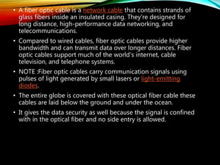
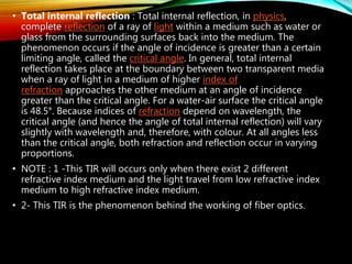
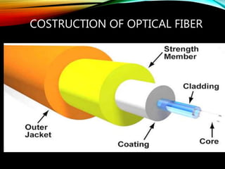
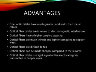
Fiber optic cables transmit data in the form of light pulses. They contain glass fibers that guide light through total internal reflection. Compared to metal cables, fiber optic cables provide higher bandwidth and can transmit data over longer distances, supporting modern internet, cable TV, and telephone systems. Fiber optic networks now span the globe and undersea, connecting cities worldwide through a vast optical fiber infrastructure.
A brief presentation about optical fiber technology. Presented by Abdessalam BENHARIRA and Laurent PANEK.
Summary
1. What is optical fiber ?
2. How it works ?
3. Different types
4. Uses
5. Advantages and disadvantages
6. Conclusion
A brief presentation about optical fiber technology. Presented by Abdessalam BENHARIRA and Laurent PANEK.
Summary
1. What is optical fiber ?
2. How it works ?
3. Different types
4. Uses
5. Advantages and disadvantages
6. Conclusion
Optical Fiber Basic Concept Which May Help You To Understand More Easily. The Slide Is Specially For Engineering Background. Anyone can get easily understand by studying this material. Thank you.
An optical fiber is a hair thin cylindrical fiber of glass or any transparent dielectric medium.
The fiber which are used for optical communication are wave guides made of transparent dielectrics.
Its function is to guide visible and infrared light over long distances.
Fiber-optic communication is a method of transmitting information from one place to another by sending pulses of light through an optical fiber. The light forms anelectromagnetic carrier wave that is modulated to carry information.
Optical fiber is used by many telecommunications companies to transmit telephone signals, Internet communication, and cable television signals.
The process of communicating using fiber-optics involves the following basic steps: Creating the optical signal involving the use of a transmitter, relaying the signal along the fiber, ensuring that the signal does not become too distorted or weak, receiving the optical signal, and converting it into an electrical signal.
Optical cable: It serves as transmission medium.
Optical detector: It is responsible for optical to electrical conversion of data and hence responsible for demodulation of the optical carrier. It may be a photodiodes, phototransistor, and photoconductors.
Electrical receiver: It is used for electrical interfacing at the receiver end of the optical link and to perform the signal processing electrically.
Destination: It is the final point at which we receive the information in the form of electrical signal.
Applications -In telecommunication field
In space applications
Broadband applications
Computer applications industrial applications
Mining applications
In medical applications
In military applications etc.
Describes Fiber Optics using Optical Ray Theory.
For comments please contact me at solo.hermelin@gmail.com.
For more presentations visit my website at http://www.solohermelin.com.
Fiber optic systems are important telecommunication
infrastructure for world-wide broadband networks. Wide
bandwidth signal transmission with low delay is a key
requirement in present day applications. Optical fibers provide
enormous and unsurpassed transmission bandwidth with
negligible latency, and are now the transmission medium of
choice for long distance and high data rate transmission in
telecommunication networks.
Garth naar - optical fibre communication telecommunicationsgarthnaar
Fibre optic communication has revolutionised the telecommunications industry. It has also made its presence widely felt within the data networking community as well. Using fibre optic cable, optical communications have enabled telecommunications links to be made over much greater distances and with much lower levels of loss in the transmission medium and possibly most important of all, fiber optical communications has enabled much higher data rates to be accommodated.
Optical communication, also known as optical telecommunication, is communication at a distance using light to carry information. It can be performed visually or by using electronic devices. The earliest basic forms of optical communication date back several millennia, while the earliest electrical device created to do so was the photophone, invented in 1880.
An optical communication system uses a transmitter, which encodes a message into an optical signal, a channel, which carries the signal to its destination, and a receiver, which reproduces the message from the received optical signal. When electronic equipment is not employed the 'receiver' is a person visually observing and interpreting a signal, which may be either simple (such as the presence of a beacon fire) or complex (such as lights using color codes or flashed in a Morse code sequence).
Modern communication relies on optical networking systems using optical fiber, optical amplifiers, lasers, switches, routers, and other related technologies. Free-space optical communication use lasers to transmit signals in space, while terrestrial forms are naturally limited by geography and weather. This article provides a basic introduction to different forms of optical communication.
Visual forms
Visual techniques such as smoke signals, beacon fires, hydraulic telegraphs, ship flags and semaphore lines were the earliest forms of optical communication.[1][2][3][4] Hydraulic telegraph semaphores date back to the 4th century BCE Greece. Distress flares are still used by mariners in emergencies, while lighthouses and navigation lights are used to communicate navigation hazards.
The heliograph uses a mirror to reflect sunlight to a distant observer.[5] When a signaler tilts the mirror to reflect sunlight, the distant observer sees flashes of light that can be used to transmit a prearranged signaling code. Naval ships often use signal lamps and Morse code in a similar way.
Aircraft pilots often use visual approach slope indicator (VASI) projected light systems to land safely, especially at night. Military aircraft landing on an aircraft carrier use a similar system to land correctly on a carrier deck. The coloured light system communicates the aircraft's height relative to a standard landing glideslope. As well, airport control towers still use Aldis lamps to transmit instructions to aircraft whose radios have failed.
Explore the innovative world of trenchless pipe repair with our comprehensive guide, "The Benefits and Techniques of Trenchless Pipe Repair." This document delves into the modern methods of repairing underground pipes without the need for extensive excavation, highlighting the numerous advantages and the latest techniques used in the industry.
Learn about the cost savings, reduced environmental impact, and minimal disruption associated with trenchless technology. Discover detailed explanations of popular techniques such as pipe bursting, cured-in-place pipe (CIPP) lining, and directional drilling. Understand how these methods can be applied to various types of infrastructure, from residential plumbing to large-scale municipal systems.
Ideal for homeowners, contractors, engineers, and anyone interested in modern plumbing solutions, this guide provides valuable insights into why trenchless pipe repair is becoming the preferred choice for pipe rehabilitation. Stay informed about the latest advancements and best practices in the field.
CFD Simulation of By-pass Flow in a HRSG module by R&R Consult.pptxR&R Consult
CFD analysis is incredibly effective at solving mysteries and improving the performance of complex systems!
Here's a great example: At a large natural gas-fired power plant, where they use waste heat to generate steam and energy, they were puzzled that their boiler wasn't producing as much steam as expected.
R&R and Tetra Engineering Group Inc. were asked to solve the issue with reduced steam production.
An inspection had shown that a significant amount of hot flue gas was bypassing the boiler tubes, where the heat was supposed to be transferred.
R&R Consult conducted a CFD analysis, which revealed that 6.3% of the flue gas was bypassing the boiler tubes without transferring heat. The analysis also showed that the flue gas was instead being directed along the sides of the boiler and between the modules that were supposed to capture the heat. This was the cause of the reduced performance.
Based on our results, Tetra Engineering installed covering plates to reduce the bypass flow. This improved the boiler's performance and increased electricity production.
It is always satisfying when we can help solve complex challenges like this. Do your systems also need a check-up or optimization? Give us a call!
Work done in cooperation with James Malloy and David Moelling from Tetra Engineering.
More examples of our work https://www.r-r-consult.dk/en/cases-en/
Industrial Training at Shahjalal Fertilizer Company Limited (SFCL)MdTanvirMahtab2
This presentation is about the working procedure of Shahjalal Fertilizer Company Limited (SFCL). A Govt. owned Company of Bangladesh Chemical Industries Corporation under Ministry of Industries.
About
Indigenized remote control interface card suitable for MAFI system CCR equipment. Compatible for IDM8000 CCR. Backplane mounted serial and TCP/Ethernet communication module for CCR remote access. IDM 8000 CCR remote control on serial and TCP protocol.
• Remote control: Parallel or serial interface.
• Compatible with MAFI CCR system.
• Compatible with IDM8000 CCR.
• Compatible with Backplane mount serial communication.
• Compatible with commercial and Defence aviation CCR system.
• Remote control system for accessing CCR and allied system over serial or TCP.
• Indigenized local Support/presence in India.
• Easy in configuration using DIP switches.
Technical Specifications
Indigenized remote control interface card suitable for MAFI system CCR equipment. Compatible for IDM8000 CCR. Backplane mounted serial and TCP/Ethernet communication module for CCR remote access. IDM 8000 CCR remote control on serial and TCP protocol.
Key Features
Indigenized remote control interface card suitable for MAFI system CCR equipment. Compatible for IDM8000 CCR. Backplane mounted serial and TCP/Ethernet communication module for CCR remote access. IDM 8000 CCR remote control on serial and TCP protocol.
• Remote control: Parallel or serial interface
• Compatible with MAFI CCR system
• Copatiable with IDM8000 CCR
• Compatible with Backplane mount serial communication.
• Compatible with commercial and Defence aviation CCR system.
• Remote control system for accessing CCR and allied system over serial or TCP.
• Indigenized local Support/presence in India.
Application
• Remote control: Parallel or serial interface.
• Compatible with MAFI CCR system.
• Compatible with IDM8000 CCR.
• Compatible with Backplane mount serial communication.
• Compatible with commercial and Defence aviation CCR system.
• Remote control system for accessing CCR and allied system over serial or TCP.
• Indigenized local Support/presence in India.
• Easy in configuration using DIP switches.
Welcome to WIPAC Monthly the magazine brought to you by the LinkedIn Group Water Industry Process Automation & Control.
In this month's edition, along with this month's industry news to celebrate the 13 years since the group was created we have articles including
A case study of the used of Advanced Process Control at the Wastewater Treatment works at Lleida in Spain
A look back on an article on smart wastewater networks in order to see how the industry has measured up in the interim around the adoption of Digital Transformation in the Water Industry.
Hybrid optimization of pumped hydro system and solar- Engr. Abdul-Azeez.pdffxintegritypublishin
Advancements in technology unveil a myriad of electrical and electronic breakthroughs geared towards efficiently harnessing limited resources to meet human energy demands. The optimization of hybrid solar PV panels and pumped hydro energy supply systems plays a pivotal role in utilizing natural resources effectively. This initiative not only benefits humanity but also fosters environmental sustainability. The study investigated the design optimization of these hybrid systems, focusing on understanding solar radiation patterns, identifying geographical influences on solar radiation, formulating a mathematical model for system optimization, and determining the optimal configuration of PV panels and pumped hydro storage. Through a comparative analysis approach and eight weeks of data collection, the study addressed key research questions related to solar radiation patterns and optimal system design. The findings highlighted regions with heightened solar radiation levels, showcasing substantial potential for power generation and emphasizing the system's efficiency. Optimizing system design significantly boosted power generation, promoted renewable energy utilization, and enhanced energy storage capacity. The study underscored the benefits of optimizing hybrid solar PV panels and pumped hydro energy supply systems for sustainable energy usage. Optimizing the design of solar PV panels and pumped hydro energy supply systems as examined across diverse climatic conditions in a developing country, not only enhances power generation but also improves the integration of renewable energy sources and boosts energy storage capacities, particularly beneficial for less economically prosperous regions. Additionally, the study provides valuable insights for advancing energy research in economically viable areas. Recommendations included conducting site-specific assessments, utilizing advanced modeling tools, implementing regular maintenance protocols, and enhancing communication among system components.
Student information management system project report ii.pdfKamal Acharya
Our project explains about the student management. This project mainly explains the various actions related to student details. This project shows some ease in adding, editing and deleting the student details. It also provides a less time consuming process for viewing, adding, editing and deleting the marks of the students.
2. • A fiber optic cable is a network cable that contains strands of
glass fibers inside an insulated casing. They're designed for
long distance, high-performance data networking, and
telecommunications.
• Compared to wired cables, fiber optic cables provide higher
bandwidth and can transmit data over longer distances. Fiber
optic cables support much of the world's internet, cable
television, and telephone systems.
• NOTE :Fiber optic cables carry communication signals using
pulses of light generated by small lasers or light-emitting
diodes.
• The entire globe is covered with these optical fiber cable these
cables are laid below the ground and under the ocean.
• It gives the data security as well because the signal is confined
with in the optical fiber and no side entry is allowed.
3. • Total internal reflection : Total internal reflection, in physics,
complete reflection of a ray of light within a medium such as water or
glass from the surrounding surfaces back into the medium. The
phenomenon occurs if the angle of incidence is greater than a certain
limiting angle, called the critical angle. In general, total internal
reflection takes place at the boundary between two transparent media
when a ray of light in a medium of higher index of
refraction approaches the other medium at an angle of incidence
greater than the critical angle. For a water-air surface the critical angle
is 48.5°. Because indices of refraction depend on wavelength, the
critical angle (and hence the angle of total internal reflection) will vary
slightly with wavelength and, therefore, with colour. At all angles less
than the critical angle, both refraction and reflection occur in varying
proportions.
• NOTE : 1 -This TIR will occurs only when there exist 2 different
refractive index medium and the light travel from low refractive index
medium to high refractive index medium.
• 2- This TIR is the phenomenon behind the working of fiber optics.
5. WORKING OF OPTICAL FIBER CABLES
• Fiber optics transmit data in the form of light particles --
or photons -- that pulse through a fiber optic cable. The glass
fiber core and the cladding each have a different refractive index
that bends incoming light at a certain angle. When light signals
are sent through the fiber optic cable, they reflect off the core
and cladding in a series of zig-zag bounces, adhering to a
process called total internal reflection. The light signals do not
travel at the speed of light because of the denser glass layers,
instead traveling about 30% slower than the speed of light. To
renew, or boost, the signal throughout its journey, fiber optics
transmission sometimes requires repeaters at distant intervals to
regenerate the optical signal by converting it to an electrical
signal, processing that electrical signal and retransmitting the
optical signal.
• Fiber optic cables are moving toward supporting up to 10-Gbps
signals. Typically, as the bandwidth capacity of a fiber optic cable
increases, the more expensive it becomes.
6.
7.
8.
9.
10.
11. OPTICAL FIBER IN LAN
• MULTI – MODE
1. Multi-mode optical fiber is a type of optical fiber mostly
used for communication over short distances
2. Typical multi-mode links have data rates of 10 Mbit/s to 10
Gbit/s over link lengths of up to 600 meters
12. • The core size of multimode fiber is very large as compared to
single mode so it allows light to bounce around inside the fiber
optics
• The amplitude of the signal in the input is drastically reduced at
the output
• It can only be used for short distances
13.
14. FAST ETHERNET
• 100BASE-FX is a version of fast ethernet over optical
fiber.
• Transmission distance
a) Half duplex – 400meters because of collision detection
b) Full duplex – Up to 2 km
16. ADVANTAGES
• Fiber optic cables have much greater band width than metal
cables.
• Optical fiber cables are immune to electromagnetic interferance.
• Optical fibers have a higher carrying capacity.
• Optical fibers are much thinner and lighter compared to copper
wires.
• Optical fibers are difficult to tap
• Optical fibers can be made cheaper compared to metal wires.
• Optical fiber cables use light signal unlike electrical signals
transmitted in copper wires.
17. DISADVANTAGES
• Optical fibers are difficult to splice.
• Optical fibers are more expensive to install.
• Optical fiber cables are highly susceptible to
being damaged.
• Optical fibers are highly fragile.
• Optical cables can't be curved.
18. OPTICAL FIBER NETWORKS
Virtually every phone call we make today, every text message we
send, every internet-based application and service we use is at
some point converted to photons that travel down a vast
network of optical fibers. more than two billion kilometers of
optical fibers have been deployed, a string of glass that could be
wrapped around the globe more than 50,000 times. well over
100 million people now enjoy fiber optic connections directly to
their homes.
• Optical fibers also link up the majority of cell towers, where the
radio frequency photons picked up from billions of mobile
phone users are immediately converted to infrared photons for
efficient fiber optic backhaul into all-fiber metropolitan,
regional, long-haul and submarine networks that connect cities,
span countries and bridge continents.
19. The role of optical fiber communication technologies is to ensure that
cost-effective network traffic scaling can continue to enable future
communications services as an underpinning of today’s digital
information society. this article overviews the scaling of optical fiber
communications, highlights practical as well as fundamental problems
in network scalability, and points to some solutions currently being
explored by the global fiber optic communications community.
20. THE MODERN TRANSPORT NETWORK
• An optical transport network (see figure on facing page)
interconnects Internet Protocol (IP) packet routers that pass
data packets from a data source to the intended recipient,
preferably along minimum-hop transmission paths.
• These routers are connected through optical client
interfaces, which today offer connections of up to 100
Gbit/s over distances of around 40 km. Compact and low-
cost client interfaces can directly tie a router to other
nearby routers or connect a router to an optical transport
system that in turn establishes a connection to distant
routers.
21. • These signals can traverse thousands of kilometers of fiber
without any intermediate electronic processing, passing
only through optical amplifiers and optical filter
components that can be dynamically reconfigured to add
and drop signals or to switch them to different parts of the
network, through reconfigurable optical add-drop
multiplexers.
• In contrast to optical client signals, optical line signals are
designed with spectral stacking in mind. Modern
wavelength division multiplexed (WDM) optical transport
systems carry about 100 optical signals at up to 200 Gbit/s
each, on a 50 GHz optical frequency grid, for an overall
capacity of about 20 Tbit/s on a single optical fiber.