Download as PDF, PPTX
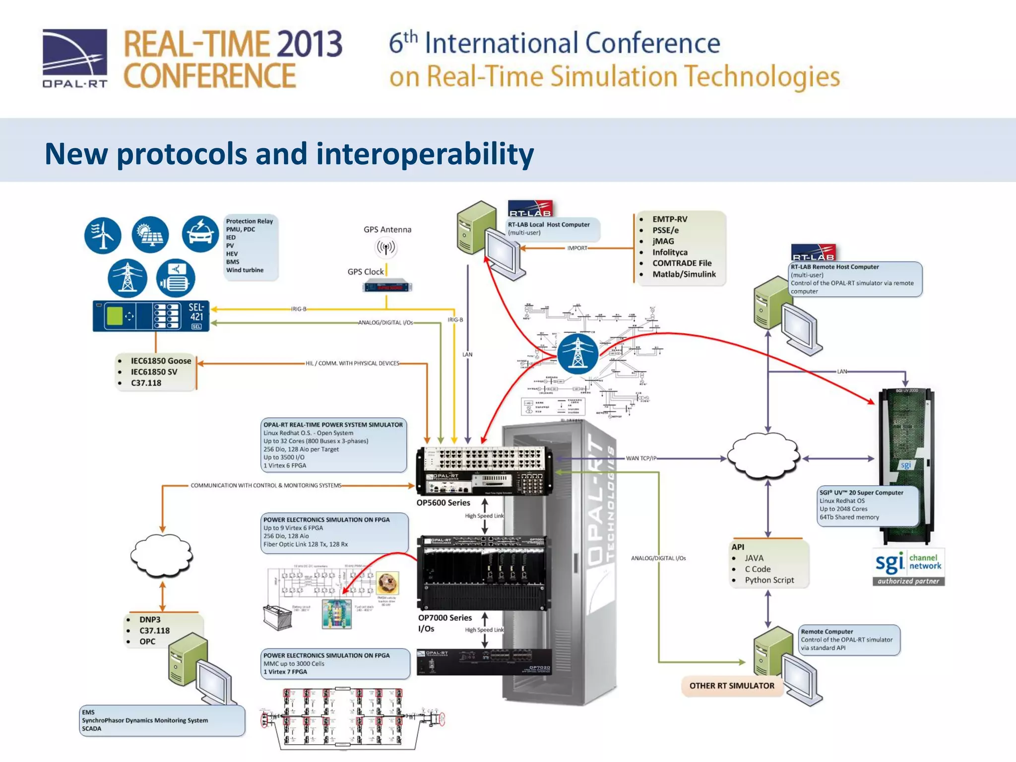
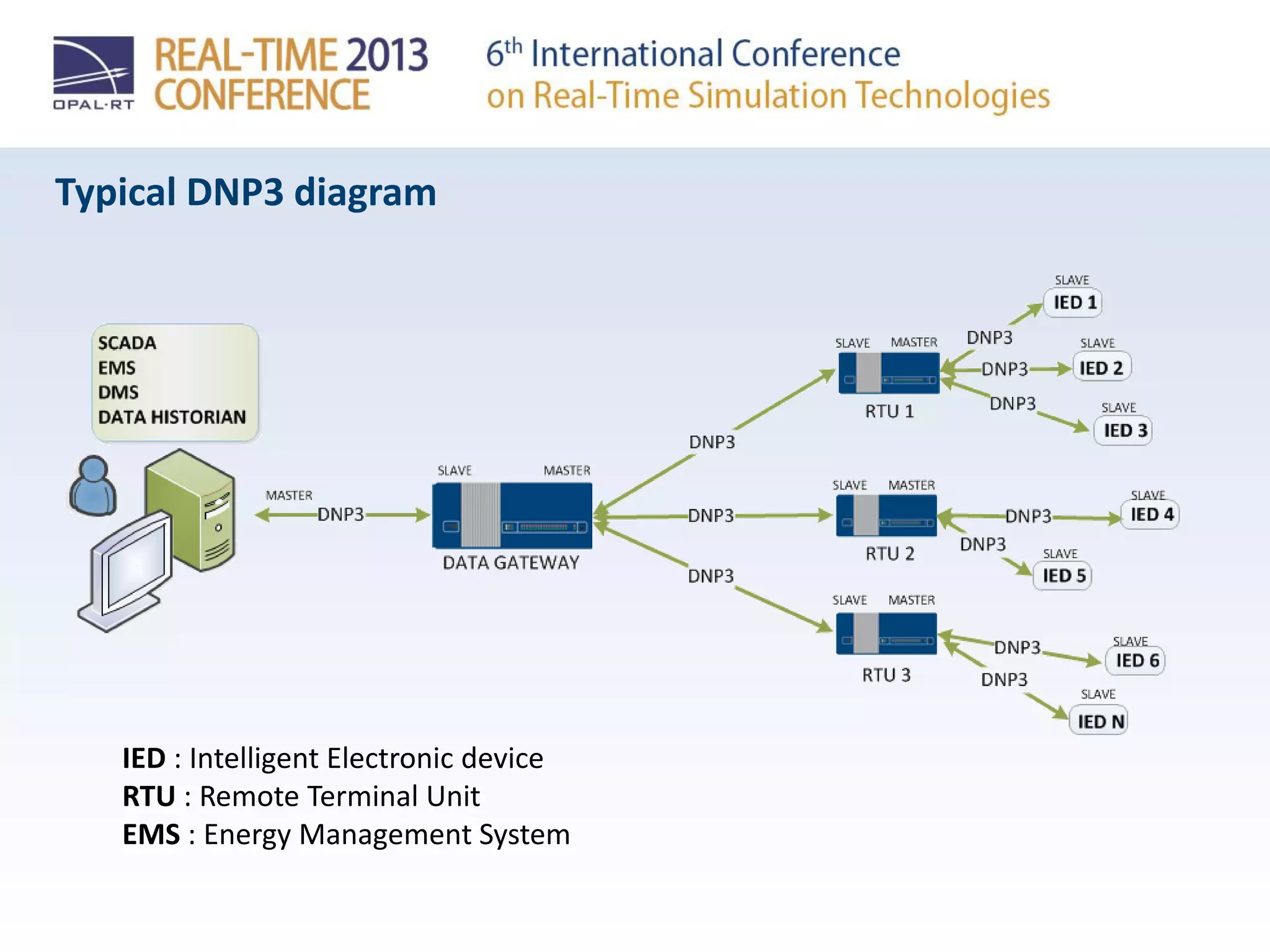
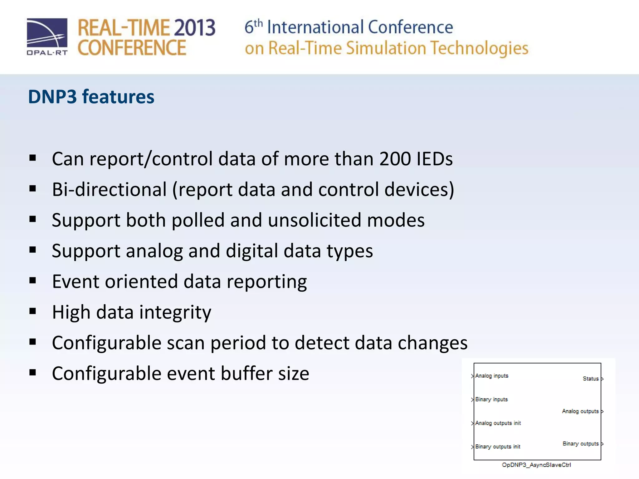
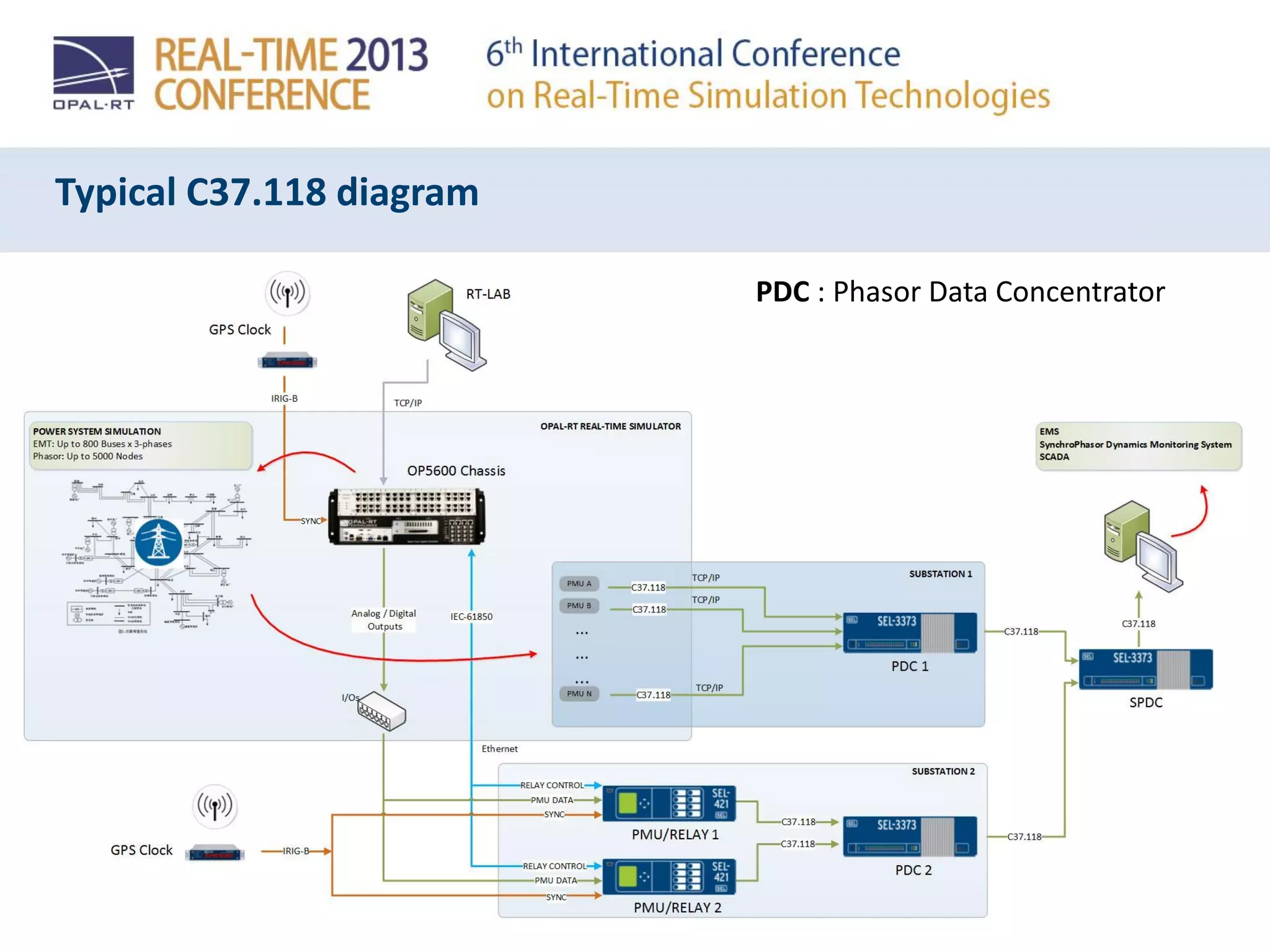
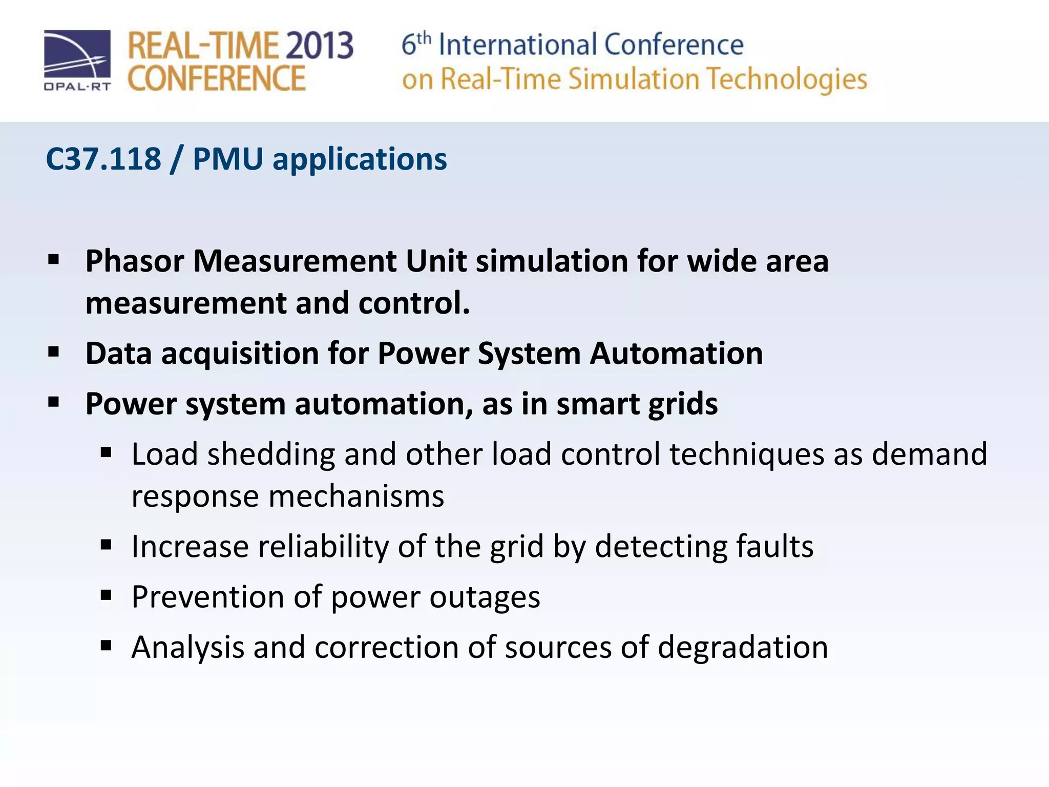
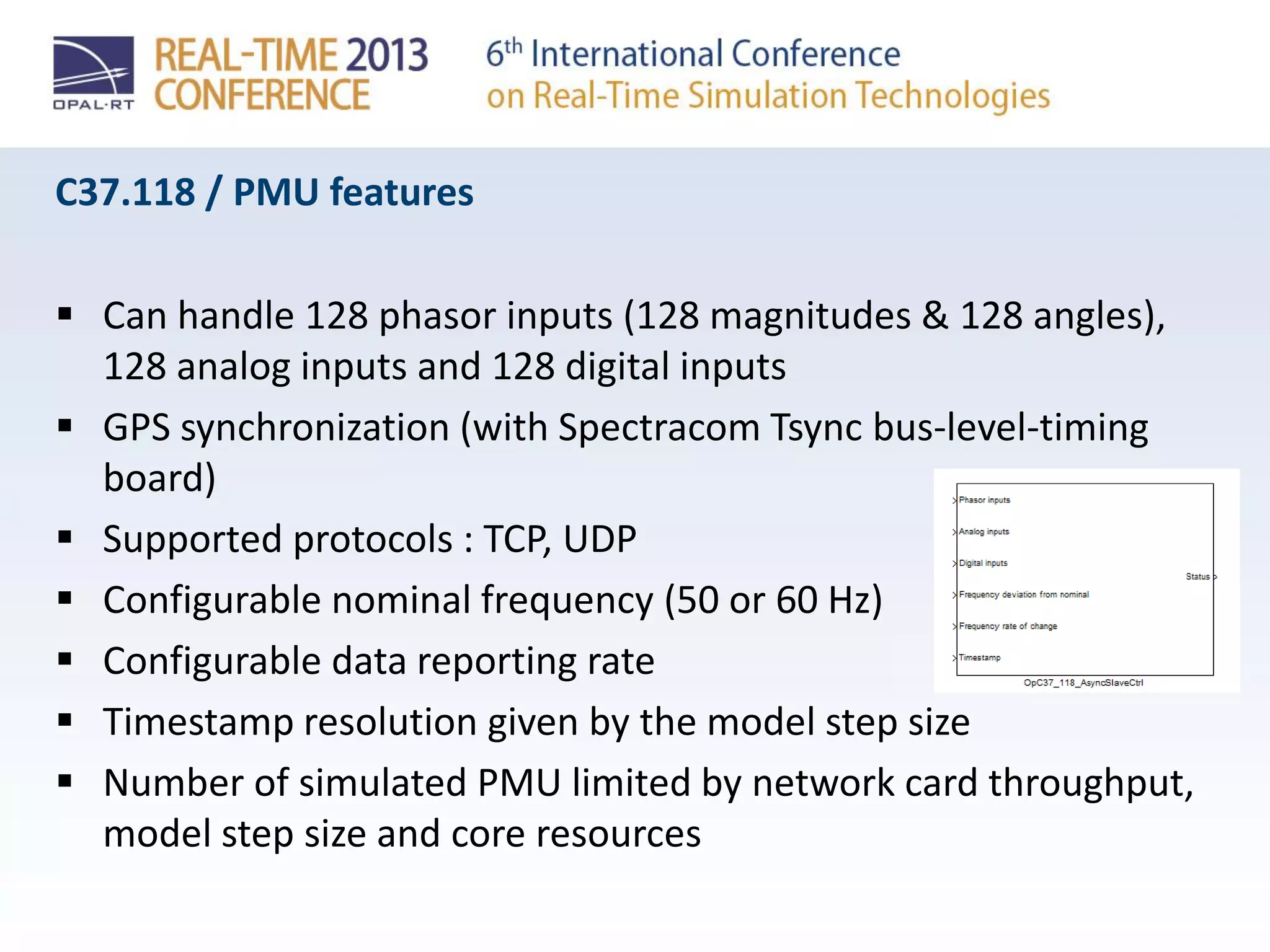
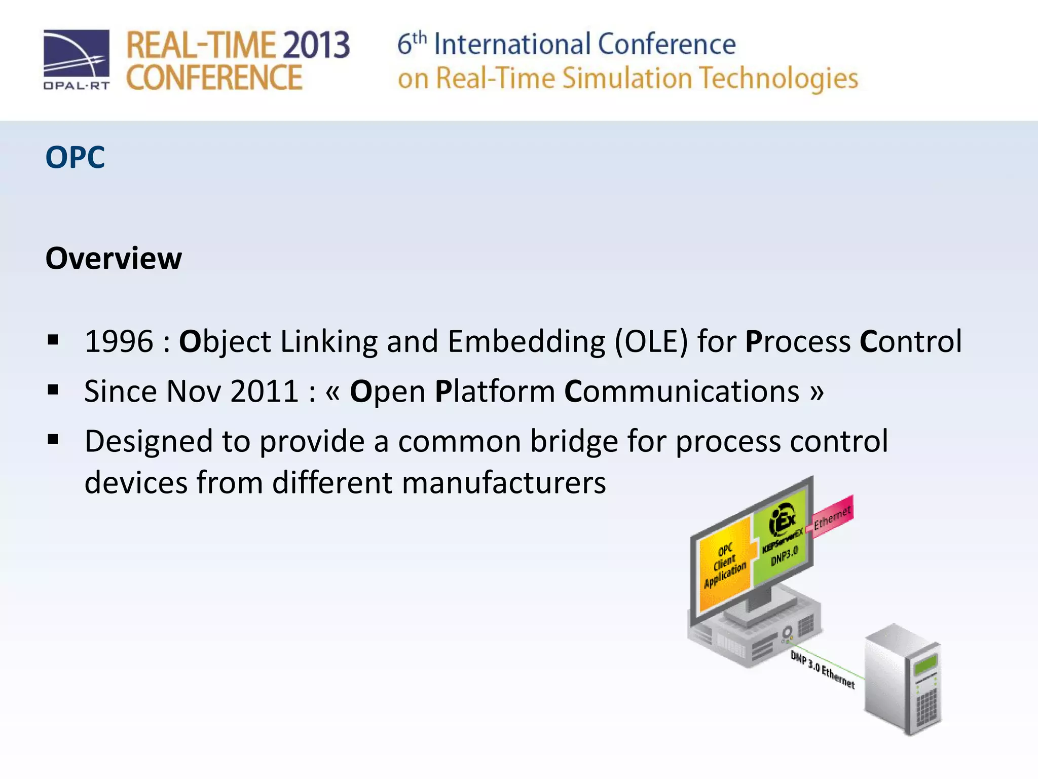
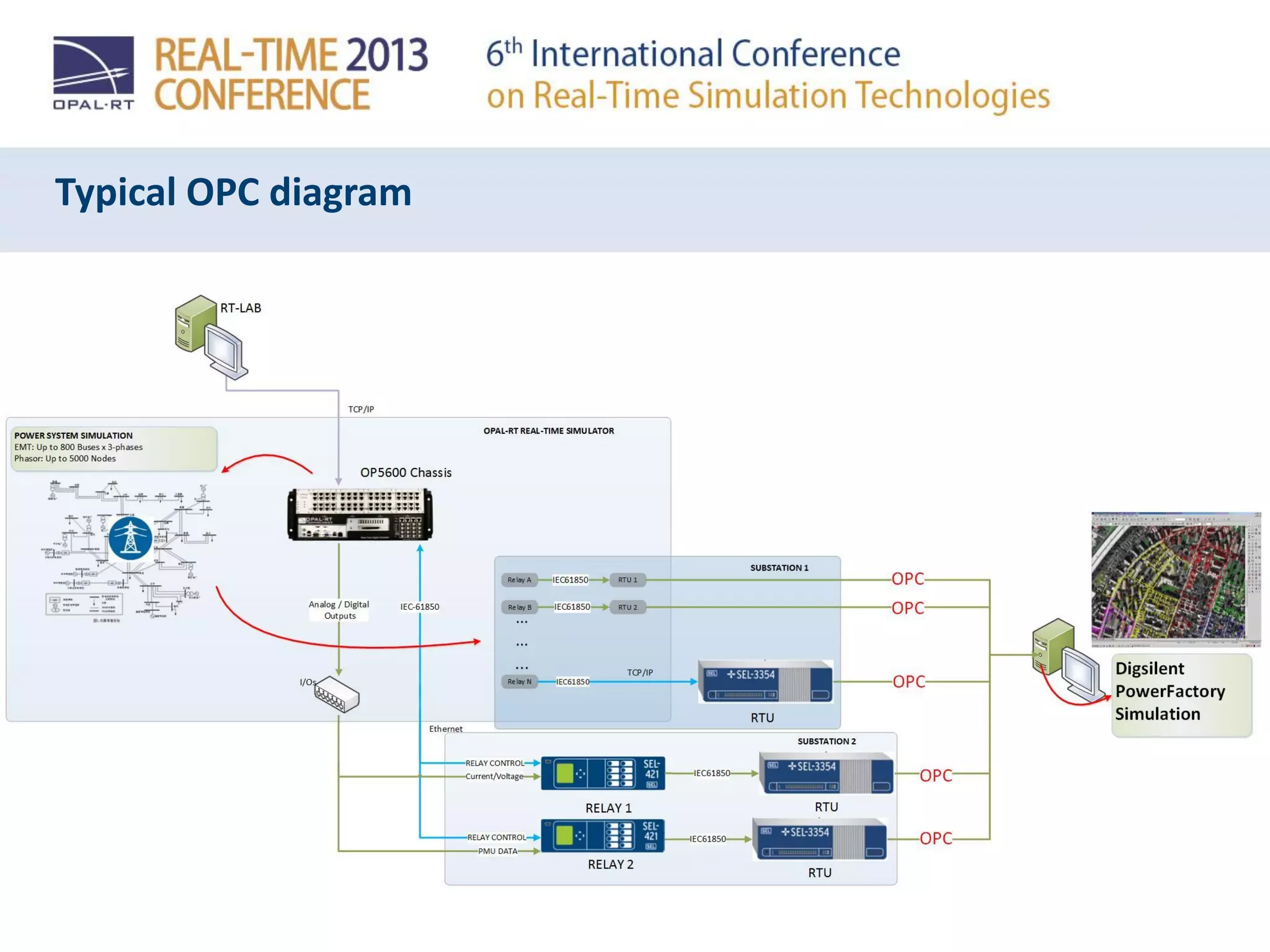
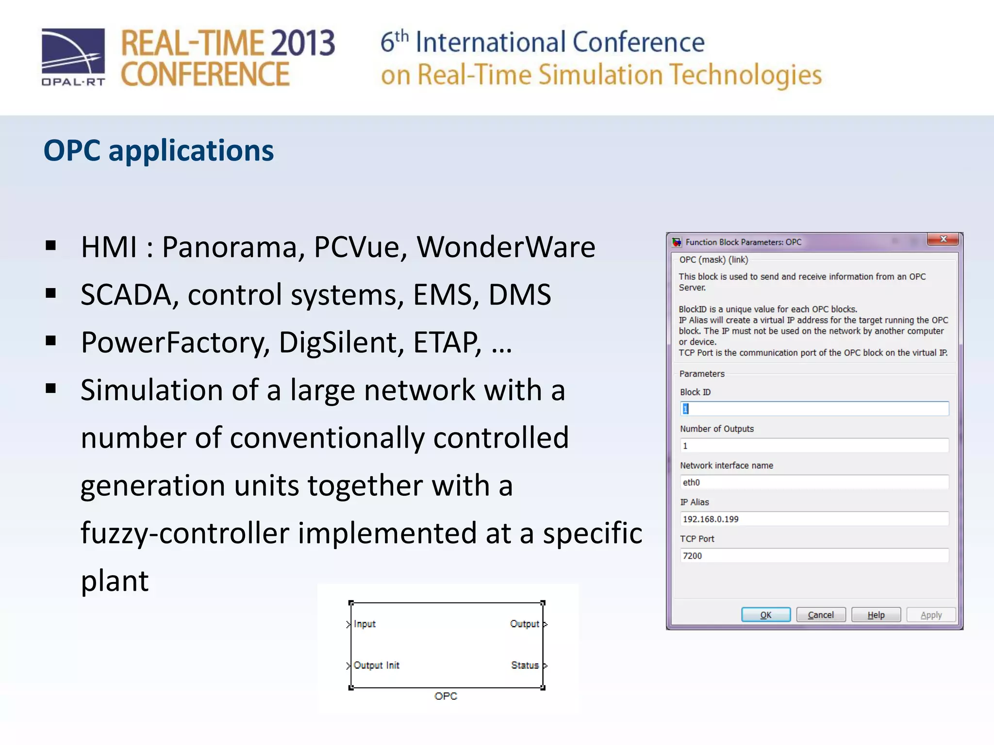
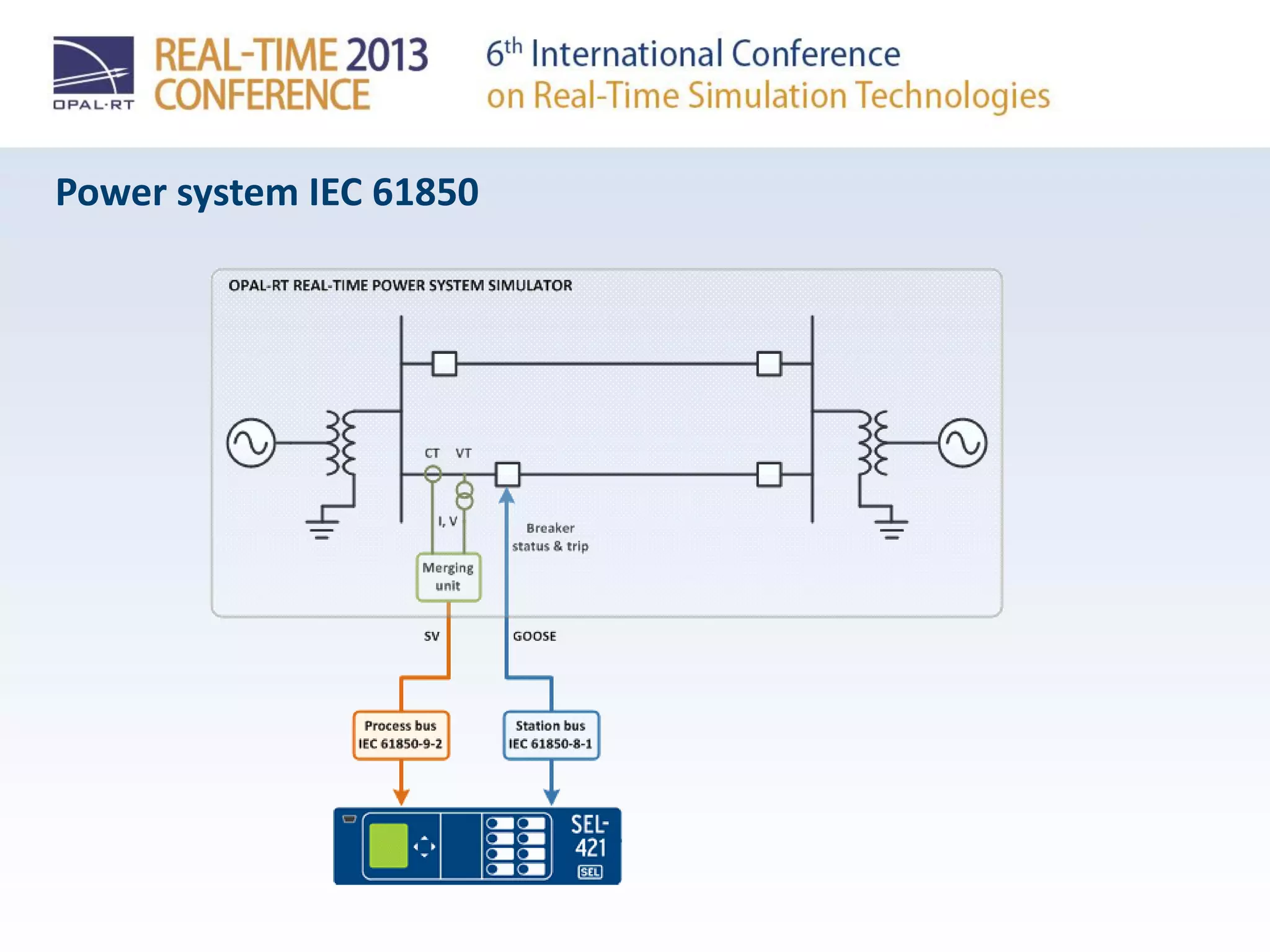
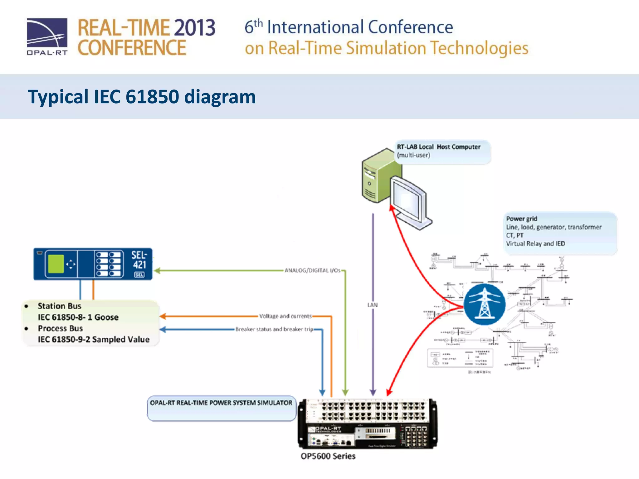
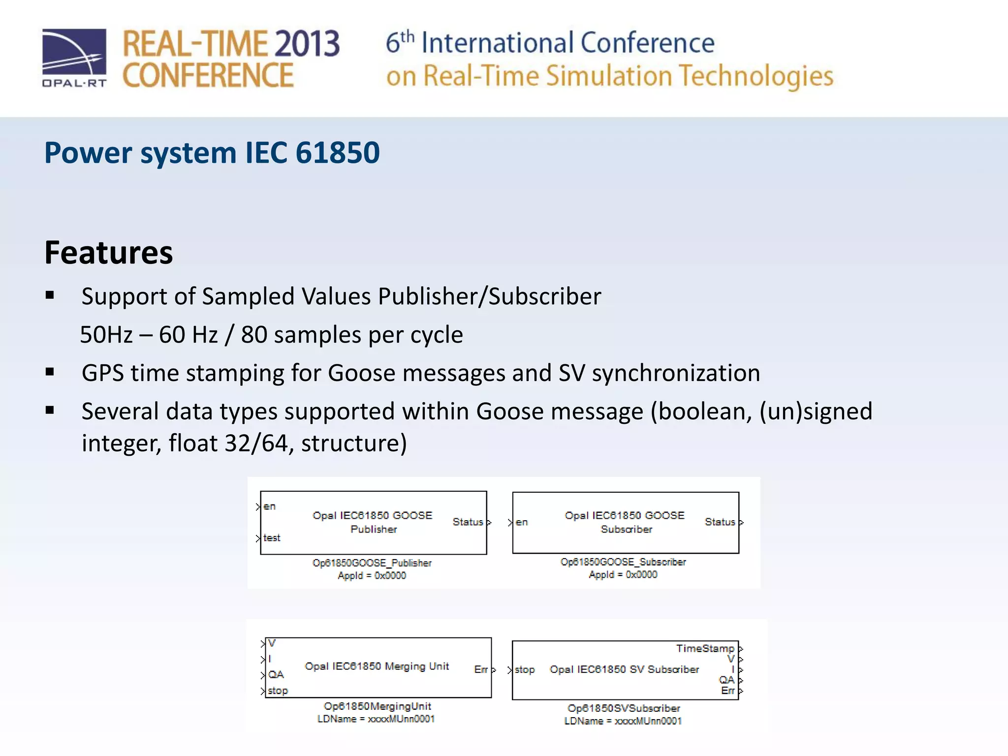
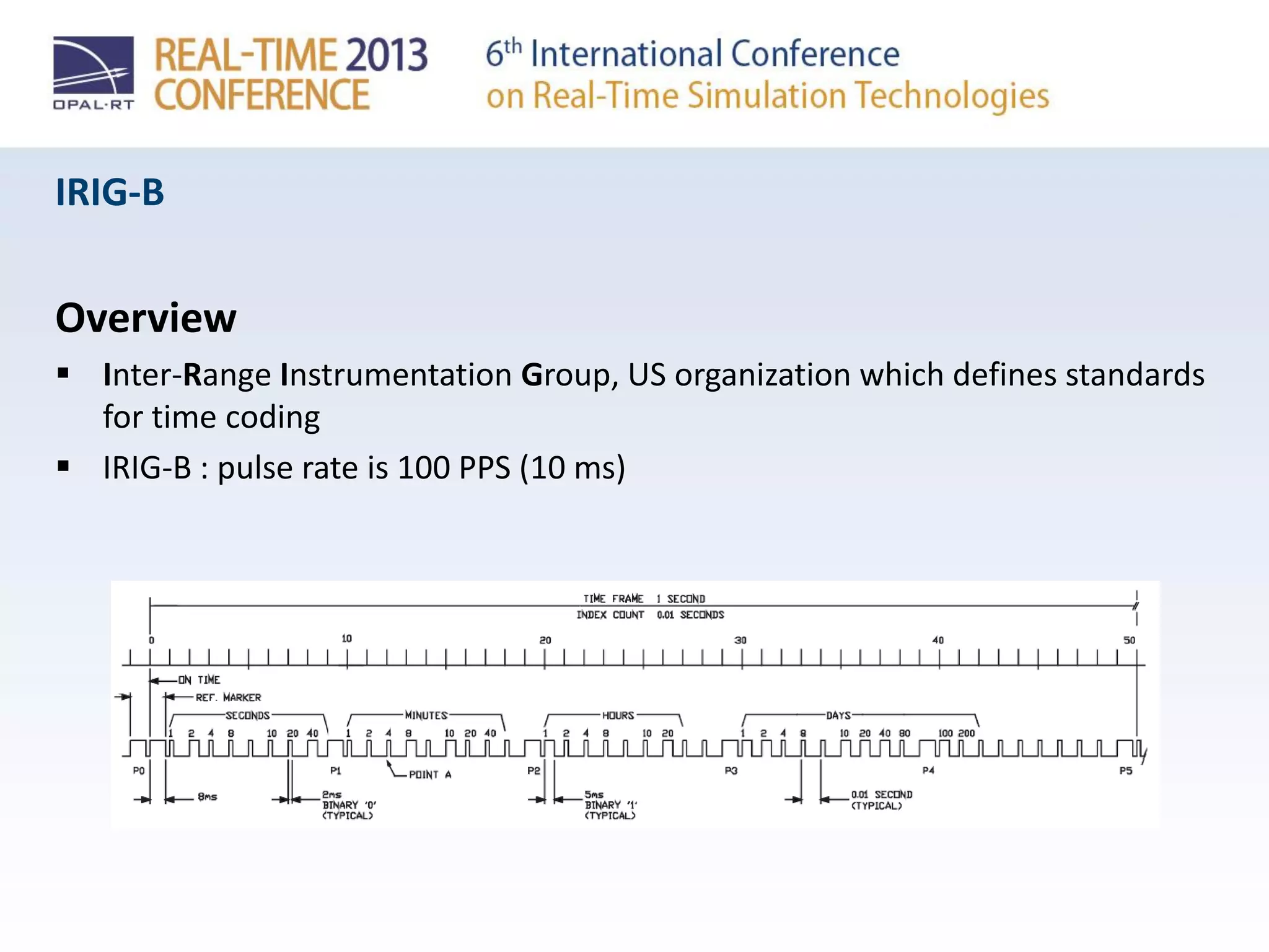
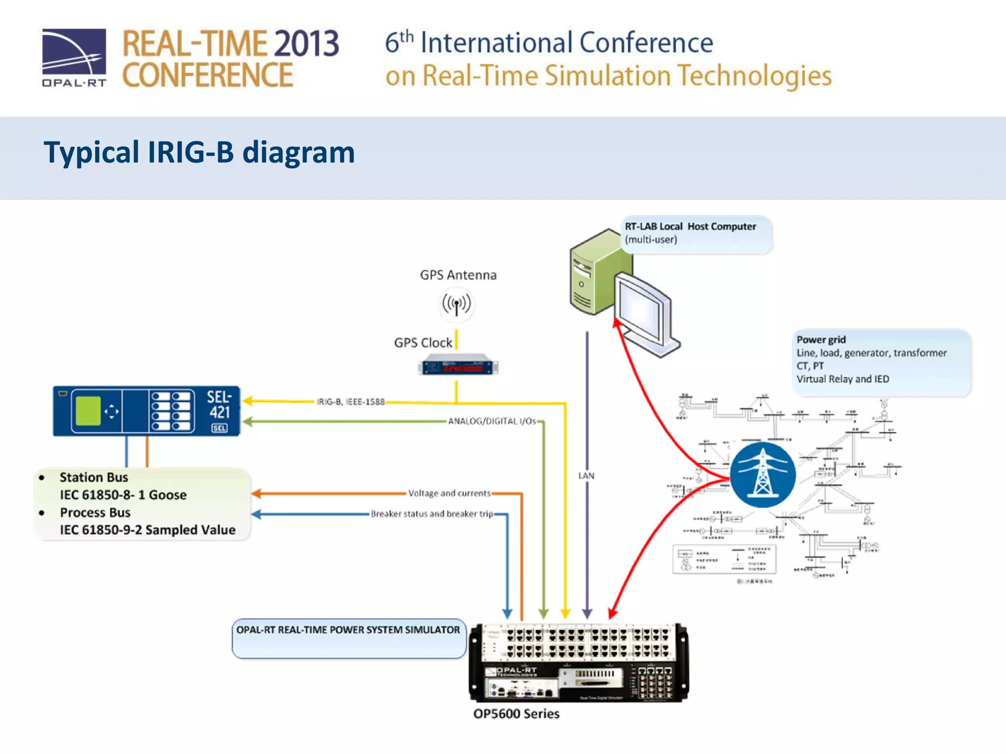

This document discusses various communication protocols used in power systems and smart grids. It provides overviews of DNP3, C37.118, OPC, IEC 61850 and IRIG-B protocols. DNP3 allows communication between intelligent electronic devices and SCADA/EMS systems to monitor and control electrical networks. C37.118 defines synchronized phasor measurements for wide area monitoring. OPC provides a common interface for process control devices. IEC 61850 specifies communication for substation automation. IRIG-B transmits a timecode signal for synchronization. The protocols support bidirectional communication of measurements and enable interoperability between different devices.


![Vibe Coding vs. Spec-Driven Development [Free Meetup]](https://cdn.slidesharecdn.com/ss_thumbnails/vibecodingvsspecdrivendevelopment-251209105622-43f455e7-thumbnail.jpg?width=640&height=640&fit=bounds)

