The document discusses communication protocols for embedded and real-time systems. It begins by introducing real-time systems and distributed real-time systems. It then discusses the Open Systems Interconnection model and its layers. The document covers different network architectures, concepts in embedded communication like event-based and state-based systems. It analyzes different network protocols and their properties. Finally, it discusses several standards used in automotive, manufacturing, and military applications.


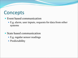

![15
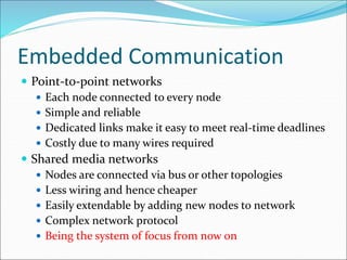
Advanced communication principles [6]
Layering
Break complexity of communication protocol into pieces easier to design and
understand
Lower levels provide services to higher level
Lower level might work with bits while higher level might work with packets of data
Physical layer
Lowest level in hierarchy
Medium to carry data from one actor (device or node) to another
Parallel communication
Physical layer capable of transporting multiple bits of data
Serial communication
Physical layer transports one bit of data at a time
Wireless communication
No physical connection needed for transport at physical layer](https://image.slidesharecdn.com/embeddedsystemcommunication-240221085959-46452d0e/85/Embedded-System-serial-Communication-ppt-15-320.jpg)
![16
Parallel communication [6]
Multiple data, control, and possibly power wires
One bit per wire
High data throughput with short distances
Typically used when connecting devices on same IC or
same circuit board
Bus must be kept short
long parallel wires result in high capacitance values which requires more
time to charge/discharge
Data misalignment between wires increases as length increases
Higher cost, bulky](https://image.slidesharecdn.com/embeddedsystemcommunication-240221085959-46452d0e/85/Embedded-System-serial-Communication-ppt-16-320.jpg)
![17
Serial communication [6]
Single data wire, possibly also control and power wires
Words transmitted one bit at a time
Higher data throughput with long distances
Less average capacitance, so more bits per unit of time
Cheaper, less bulky
More complex interfacing logic and communication protocol
Sender needs to decompose word into bits
Receiver needs to recompose bits into word
Control signals often sent on same wire as data increasing protocol
complexity](https://image.slidesharecdn.com/embeddedsystemcommunication-240221085959-46452d0e/85/Embedded-System-serial-Communication-ppt-17-320.jpg)
![18
Wireless communication [6]
Infrared (IR)
Electronic wave frequencies just below visible light spectrum
Diode emits infrared light to generate signal
Infrared transistor detects signal, conducts when exposed to
infrared light
Cheap to build
Need line of sight, limited range
Radio frequency (RF)
Electromagnetic wave frequencies in radio spectrum
Analog circuitry and antenna needed on both sides of transmission
Line of sight not needed, transmitter power determines range](https://image.slidesharecdn.com/embeddedsystemcommunication-240221085959-46452d0e/85/Embedded-System-serial-Communication-ppt-18-320.jpg)
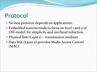
![Protocol overview [1]](https://image.slidesharecdn.com/embeddedsystemcommunication-240221085959-46452d0e/85/Embedded-System-serial-Communication-ppt-20-320.jpg)
![Connection oriented protocols
[5]
2 nodes per each connection only
If nodes are not directly connected, data is relayed
Deterministic delay between directly connected nodes,
high delay for indirectly connected nodes](https://image.slidesharecdn.com/embeddedsystemcommunication-240221085959-46452d0e/85/Embedded-System-serial-Communication-ppt-21-320.jpg)
![Polling [5]
Simple and deterministic
Needs a master node
Master periodically polls slave nodes
Consumes bandwidth
E.g. military aircraft communication
Simple slave nodes, complex master](https://image.slidesharecdn.com/embeddedsystemcommunication-240221085959-46452d0e/85/Embedded-System-serial-Communication-ppt-23-320.jpg)
![Time Division Multiple Access (TDMA)
[5]
Masters broadcasts sync signal to synchronise all
clocks
Then each node sends data on its time slot.
Similar but more efficient than polling (synchronise
once vs polling all nodes individually.
more complex nodes due to timing requirements.](https://image.slidesharecdn.com/embeddedsystemcommunication-240221085959-46452d0e/85/Embedded-System-serial-Communication-ppt-24-320.jpg)
![Token ring [5]
Ring shape network
Token (signal) is passed from node to node
Node can hold token, send message all the way round
the ring, and pass token on
Deterministic under heavy load
.](https://image.slidesharecdn.com/embeddedsystemcommunication-240221085959-46452d0e/85/Embedded-System-serial-Communication-ppt-26-320.jpg)
![Token bus [5]
Similar to token ring
Token is passed via bus simultaneously
Cable break can be dealt with by reconfiguration (like
when a node is added to or taken off the network.
Applied in manufacturing](https://image.slidesharecdn.com/embeddedsystemcommunication-240221085959-46452d0e/85/Embedded-System-serial-Communication-ppt-28-320.jpg)
![Binary countdown cont. [5]](https://image.slidesharecdn.com/embeddedsystemcommunication-240221085959-46452d0e/85/Embedded-System-serial-Communication-ppt-30-320.jpg)
![Carrier Sense Multiple Access with
Collision Dectection (CSMA/CD) [5]
Nodes wait for idle channel before transmitting.
When simultaneously transmission is detected, each
node stops and waits for random time before
resending.](https://image.slidesharecdn.com/embeddedsystemcommunication-240221085959-46452d0e/85/Embedded-System-serial-Communication-ppt-32-320.jpg)
![Carrier Sense Multiple Access with
Collision Avoidance (SCMA/CA) [5]](https://image.slidesharecdn.com/embeddedsystemcommunication-240221085959-46452d0e/85/Embedded-System-serial-Communication-ppt-34-320.jpg)
![Media access comparison [5]](https://image.slidesharecdn.com/embeddedsystemcommunication-240221085959-46452d0e/85/Embedded-System-serial-Communication-ppt-37-320.jpg)
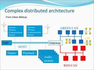
![Automotive standards [7]
Controller Area Network (CAN)
Event triggered, Arbitration
Time Triggered Protocol (TTP)
Time triggered, TDMA
Local Interconnect Network (LIN)
Time triggered, master-slave
Media Oriented System Transport (MOST)](https://image.slidesharecdn.com/embeddedsystemcommunication-240221085959-46452d0e/85/Embedded-System-serial-Communication-ppt-38-320.jpg)
![Manufacturing Automation
Standards [7]
Controller Area Network (CAN)
Arbitration
Process Network (P-NET)
Token passing and master-slave
PROcess Field Bus (PROFIBUS)
Token passing and master-slave
Factory Instrumentation Protocol (World FIP)
Centralised arbitration](https://image.slidesharecdn.com/embeddedsystemcommunication-240221085959-46452d0e/85/Embedded-System-serial-Communication-ppt-39-320.jpg)
![Military Standards [7]
MIL-STD 1553
The current 1553 data bus is widely used in military applications, with a
nominal throughput of 1 Mb/s.
MIL-STD 1773
Mil-Std-1773 defines a fiber optic bus. This system is widely used for on-
board command and telemetry transfer between military spacecraft
components, subsystems and instruments, and within complex
components themselves. 1773 AS, has a dual rate of 1 Mb/s or 20 Mb/s.
ARINC 429
A commercial aircraft data bus. It is widely implemented in the
commercial aircraft avionics industry. Performance is 100Kb/s or 12.5Kb/s.](https://image.slidesharecdn.com/embeddedsystemcommunication-240221085959-46452d0e/85/Embedded-System-serial-Communication-ppt-40-320.jpg)