Downloaded 802 times

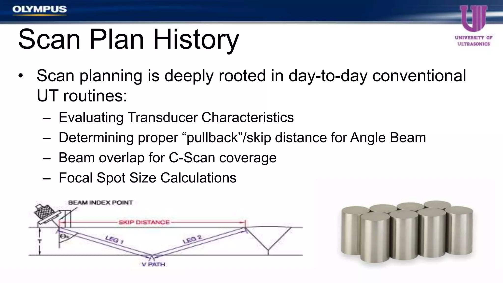
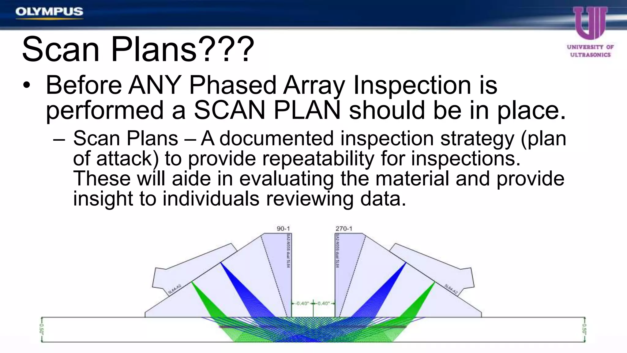
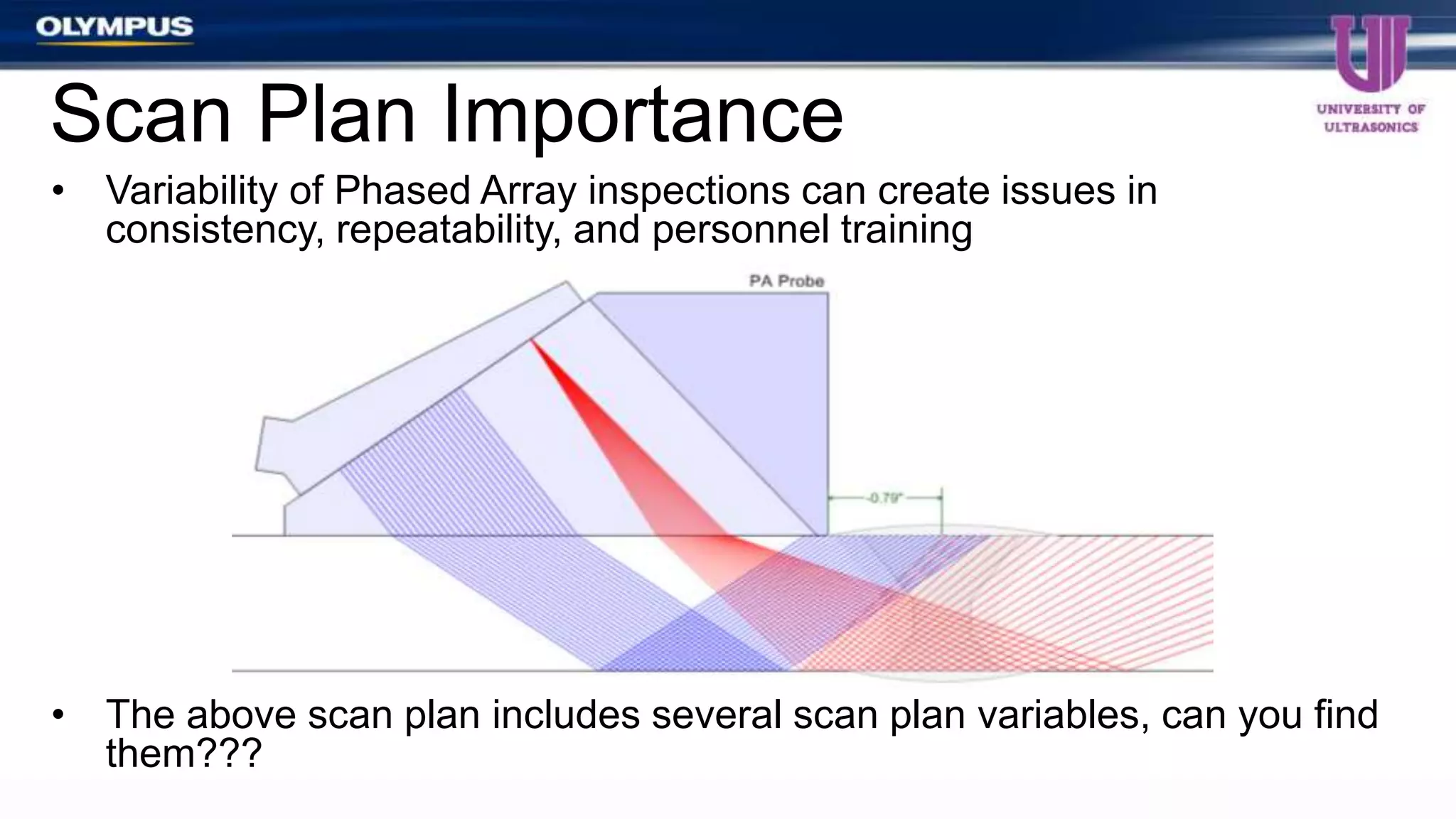
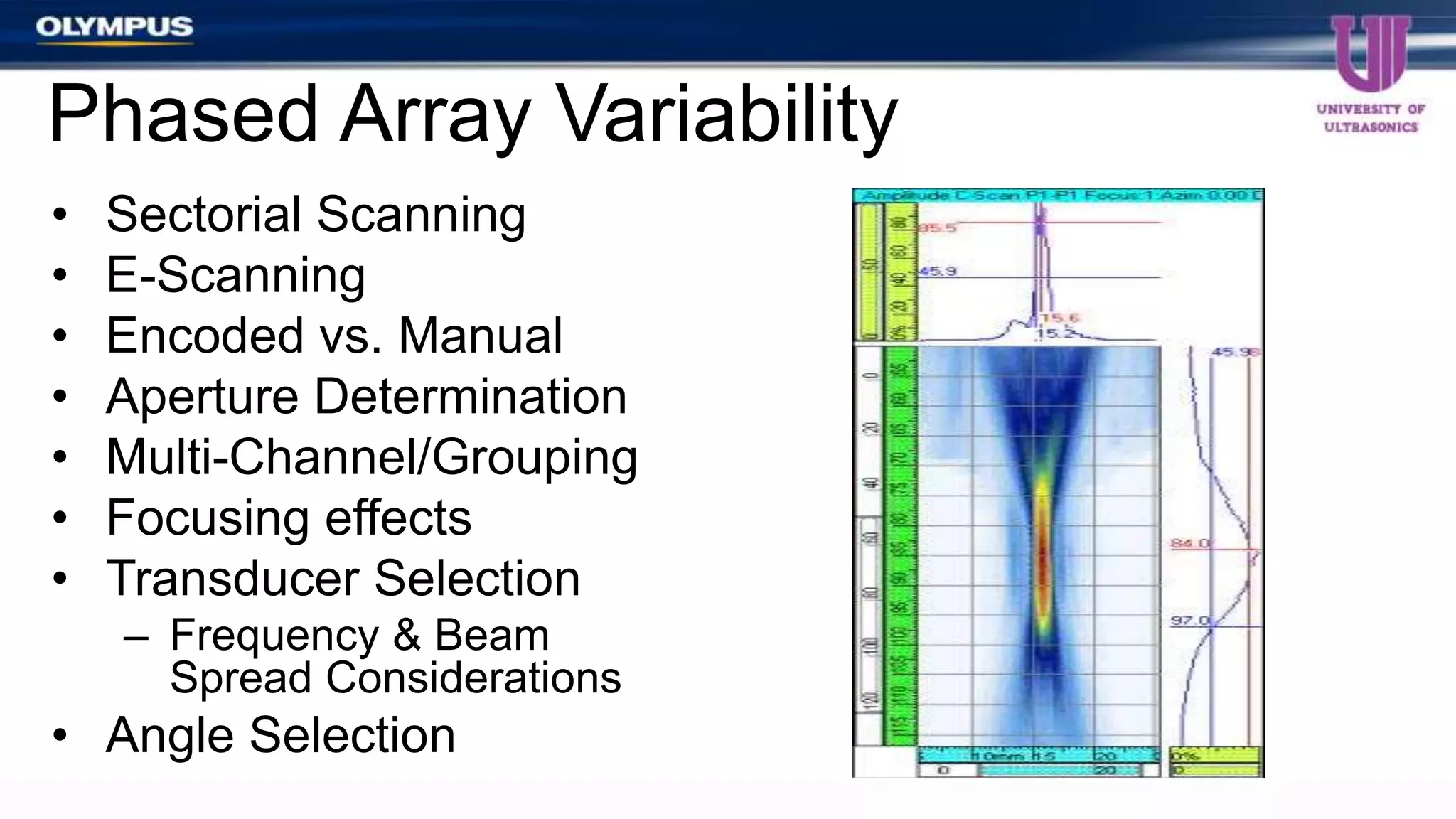
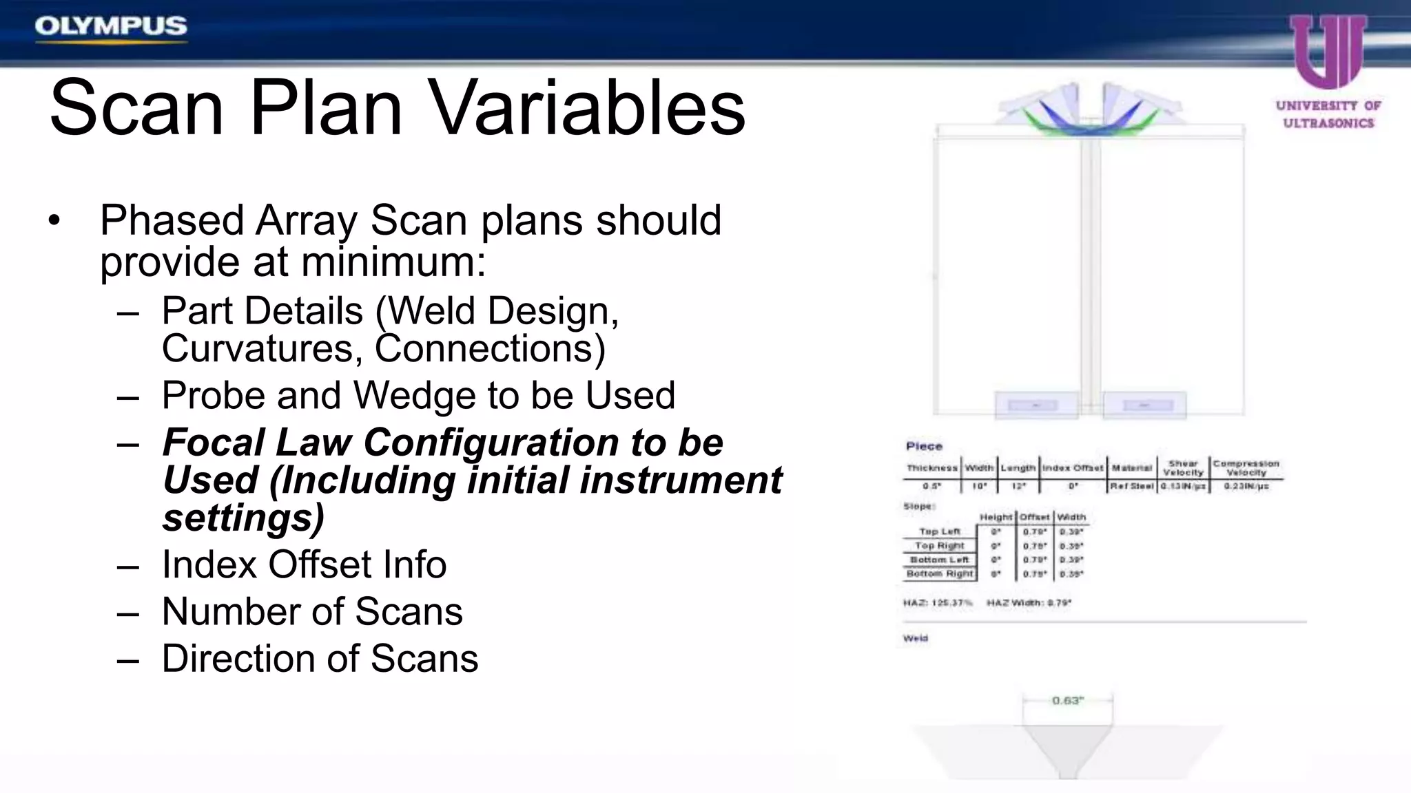
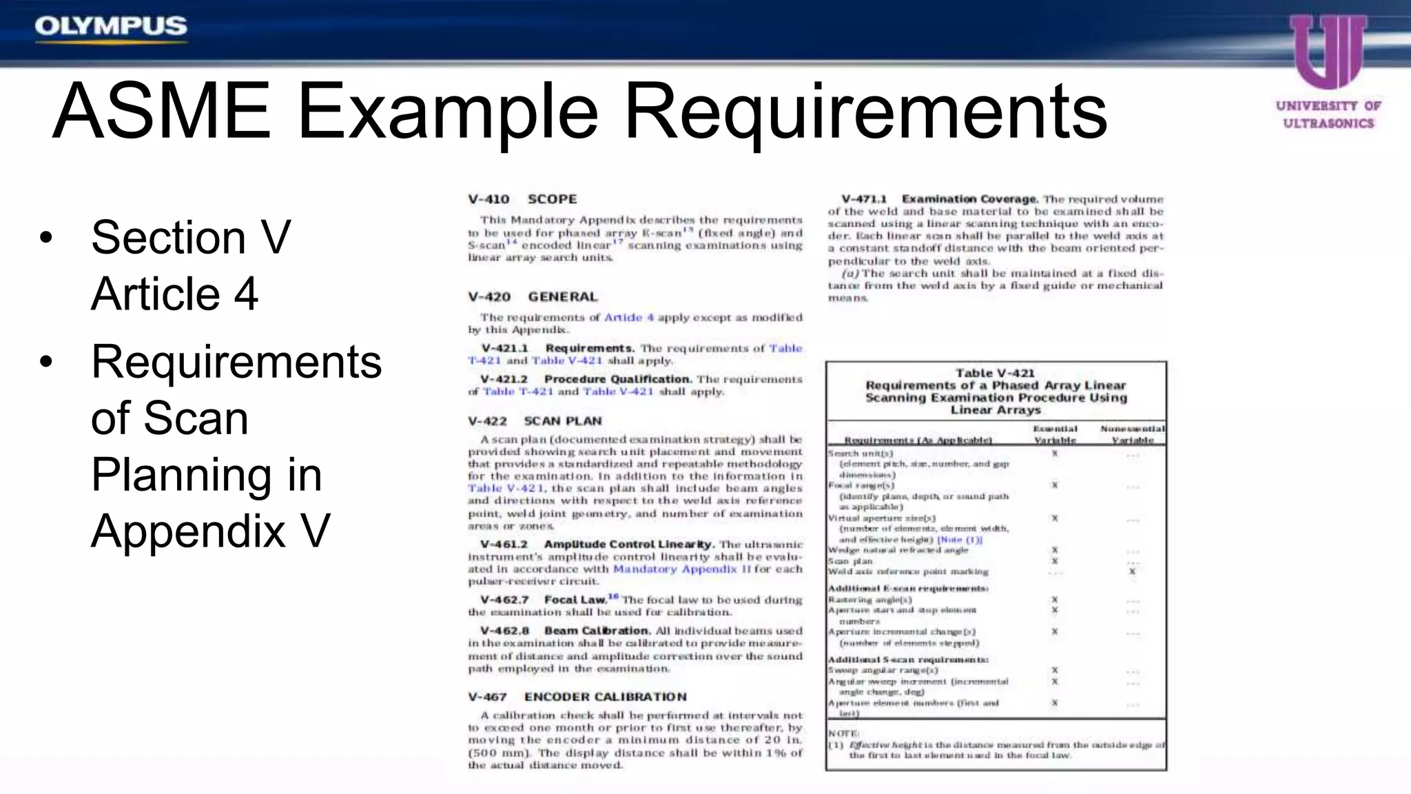
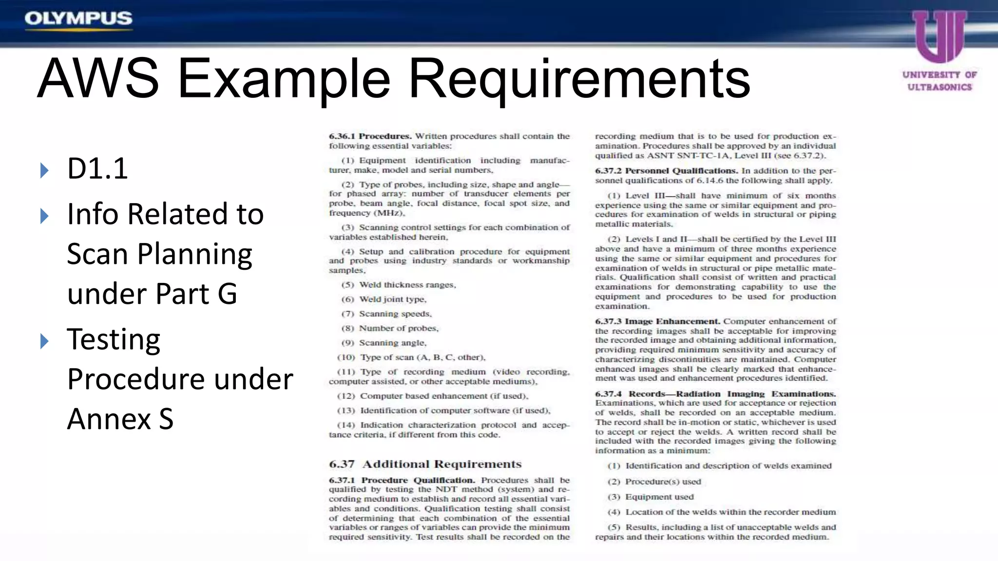
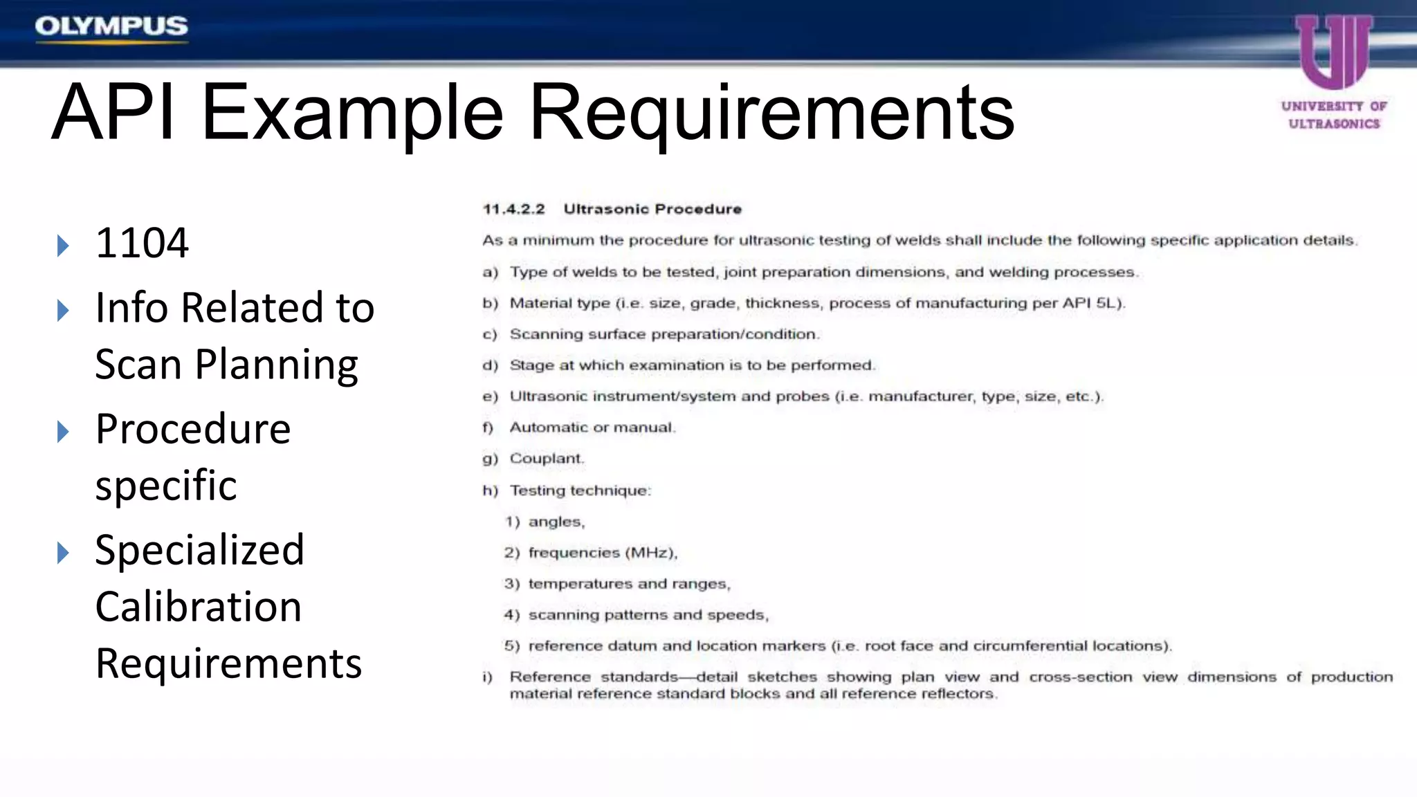
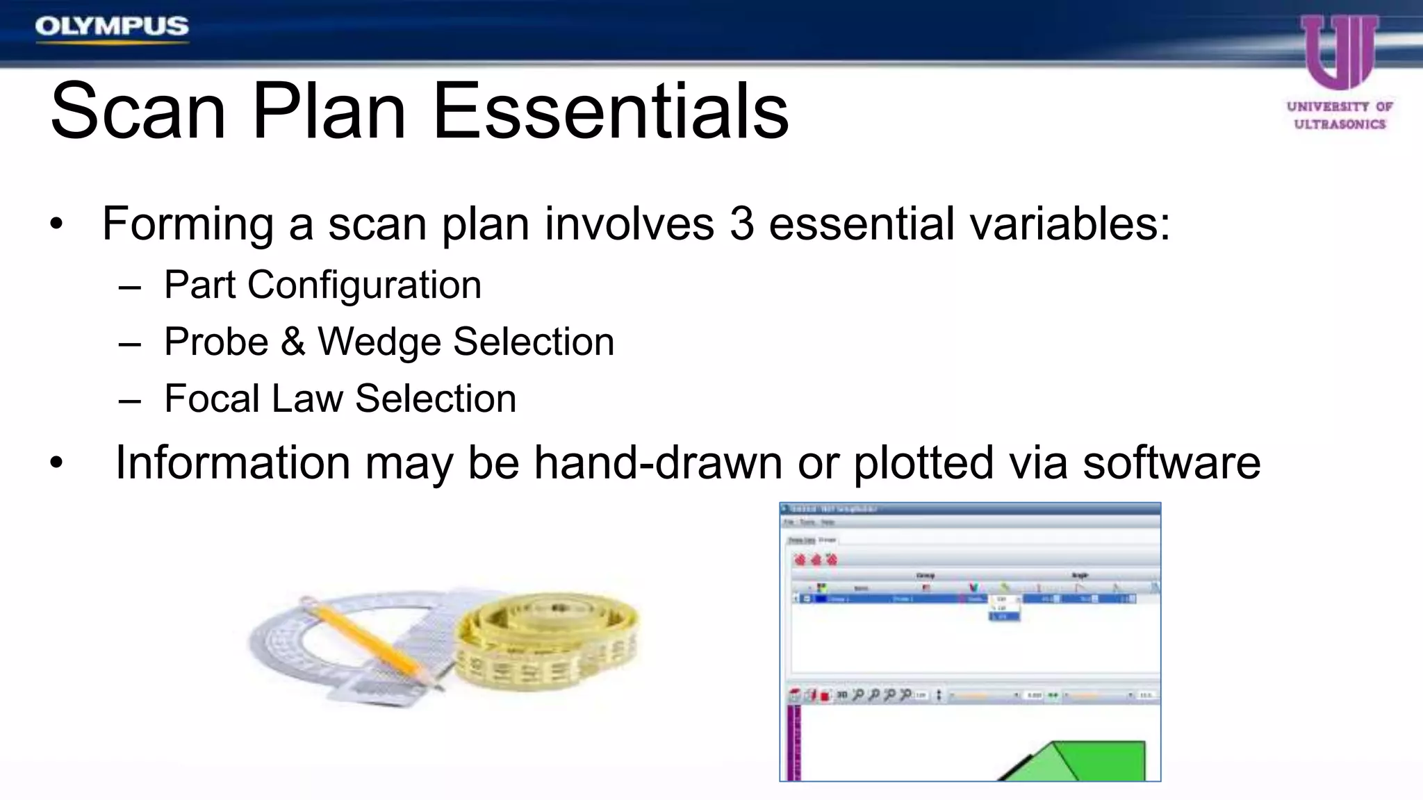
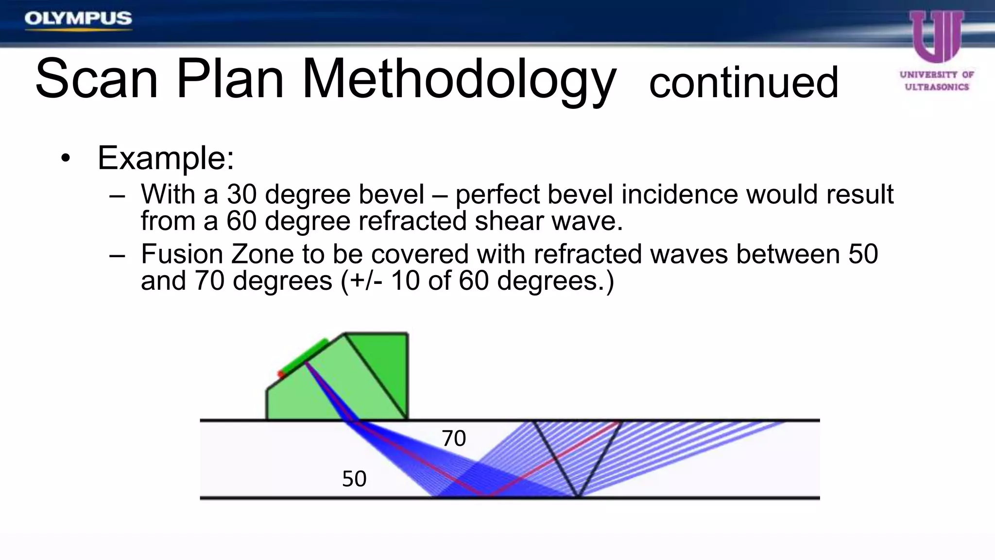


The document outlines key considerations for phased array scan planning in weld inspections, emphasizing the importance of a documented inspection strategy to ensure consistency and repeatability. It discusses variables such as probe selection, focal law configuration, and scanning methodologies, detailing the essential steps for effective coverage of weld joints. Additionally, it examines the complexities and variability inherent in phased array inspections, encouraging meticulous planning to optimize detection of potential flaws.