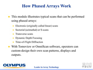
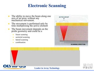
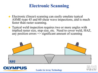
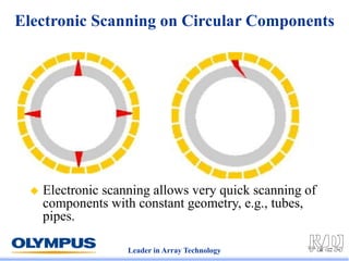
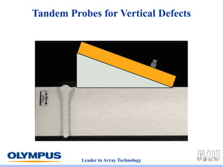
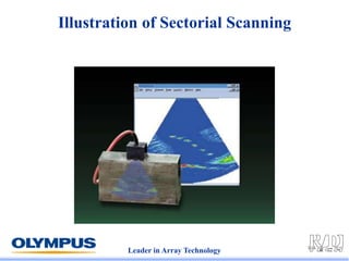
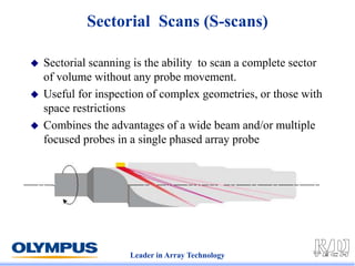
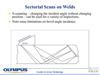
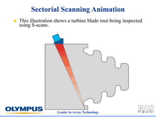
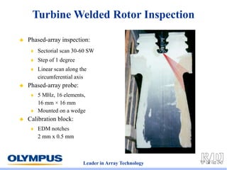
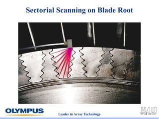
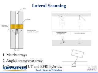
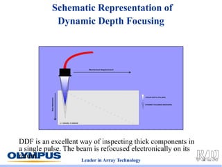
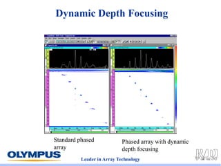
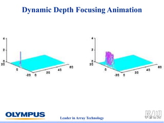
info@rd-tech.com • www.rd-tech.com
What Phased Arrays Can Do
Leader in Array Technology
How Phased Arrays Work
 This module illustrates typical scans that can be performed
using phased arrays:
 Electronic (originally called linear) scans
 Sectorial (azimuthal) or S-scans
 Transverse scans
 Dynamic Depth Focusing
 Time-of-Flight Diffraction
 With Tomoview or OmniScan software, operators can
custom-design their own scan patterns, displays and
outputs.
info@rd-tech.com • www.rd-tech.com
Electronic Scanning
Multiplex A Single Focal Law
Across the Array
Leader in Array Technology
Electronic Scanning
 The ability to move the beam along one
axis of an array without any
mechanical movement.
 The movement is performed only by
time multiplexing the active element
 The beam movement depends on the
probe geometry and could be a
 linear scanning
 sectorial scanning
 lateral scanning
 combination
Leader in Array Technology
Electronic Scanning
 Electronic (linear) scanning can easily emulate typical
ASME-type 45 and 60 shear wave inspections, and is much
faster than raster scanning.
 Typical weld inspection requires two or more angles with
implied raster size, step size, etc. Need to cover weld, HAZ,
any position errors => significant amount of scanning
Leader in Array Technology
Electronic Scanning on Circular Components
 Electronic scanning allows very quick scanning of
components with constant geometry, e.g., tubes,
pipes.
Leader in Array Technology
Tandem Probes for Vertical Defects
Leader in Array Technology
TOFD using Phased Arrays
Transmitter Receiver
Lateral wave
LW
Upper tip Lower tip
Back-wall reflection
BW
info@rd-tech.com • www.rd-tech.com
Sectorial (Azimuthal) or S-Scans
Changing the Inspection Angle
without Moving the Array
Leader in Array Technology
Illustration of Sectorial Scanning
Leader in Array Technology
Sectorial Scans (S-scans)
 Sectorial scanning is the ability to scan a complete sector
of volume without any probe movement.
 Useful for inspection of complex geometries, or those with
space restrictions
 Combines the advantages of a wide beam and/or multiple
focused probes in a single phased array probe
Leader in Array Technology
Sectorial Scans on Welds
 S-scanning – changing the incident angle without changing
position – can be used for a variety of inspections.
 Note some limitations on bevel angle incidence
Leader in Array Technology
Sectorial Scanning Animation
 This illustration shows a turbine blade root being inspected
using S-scans.
Leader in Array Technology
Turbine Welded Rotor Inspection
 Phased-array inspection:
 Sectorial scan 30-60 SW
 Step of 1 degree
 Linear scan along the
circumferential axis
 Phased-array probe:
 5 MHz, 16 elements,
16 mm × 16 mm
 Mounted on a wedge
 Calibration block:
 EDM notches
2 mm x 0.5 mm
Leader in Array Technology
Sectorial Scanning on Blade Root
Leader in Array Technology
Determining Defect Location
Leader in Array Technology
Defect Analysis using S-scans (1)
Crown
defect –
clearly
located
Defect tip
signal – easy
to identify
and size
T1 designation shows “top” or cap
Leader in Array Technology
Defect Analysis using S-scans (2)
B0 designation shows “bottom” or root
Corner
reflector
and crack
tip easily
measured
Leader in Array Technology
Combined scans -> improved POD
Leader in Array Technology
Combined S-Scan and Electronic Scan
 Combined scans
offer unique
imaging
possibilities
 Tomoview
software
enables
straightforward
set-ups
info@rd-tech.com • www.rd-tech.com
Lateral Scanning
Detecting Transverse Weld Defects
Leader in Array Technology
Lateral Scanning
1. Matrix arrays
2. Angled transverse array
3. Conventional UT and EPRI hybrids.
info@rd-tech.com • www.rd-tech.com
Dynamic Depth Focusing
Extending the Focal Range
Electronically
Leader in Array Technology
Schematic Representation of
Dynamic Depth Focusing
Mechanical Displacement
c = velocity in material
FOCUS DEPTH (PULSER)
DYNAMIC FOCUSING (RECEIVER)
Beam
displacement
DDF is an excellent way of inspecting thick components in
a single pulse. The beam is refocused electronically on its
return.
Leader in Array Technology
Dynamic Depth Focusing
Standard phased
array
Phased array with dynamic
depth focusing
Leader in Array Technology
Dynamic Depth Focusing Animation

004-What PA Can Do Phased Array Ultrasonic

  • 1.
  • 2.
    Leader in ArrayTechnology How Phased Arrays Work  This module illustrates typical scans that can be performed using phased arrays:  Electronic (originally called linear) scans  Sectorial (azimuthal) or S-scans  Transverse scans  Dynamic Depth Focusing  Time-of-Flight Diffraction  With Tomoview or OmniScan software, operators can custom-design their own scan patterns, displays and outputs.
  • 3.
    info@rd-tech.com • www.rd-tech.com ElectronicScanning Multiplex A Single Focal Law Across the Array
  • 4.
    Leader in ArrayTechnology Electronic Scanning  The ability to move the beam along one axis of an array without any mechanical movement.  The movement is performed only by time multiplexing the active element  The beam movement depends on the probe geometry and could be a  linear scanning  sectorial scanning  lateral scanning  combination
  • 5.
    Leader in ArrayTechnology Electronic Scanning  Electronic (linear) scanning can easily emulate typical ASME-type 45 and 60 shear wave inspections, and is much faster than raster scanning.  Typical weld inspection requires two or more angles with implied raster size, step size, etc. Need to cover weld, HAZ, any position errors => significant amount of scanning
  • 6.
    Leader in ArrayTechnology Electronic Scanning on Circular Components  Electronic scanning allows very quick scanning of components with constant geometry, e.g., tubes, pipes.
  • 7.
    Leader in ArrayTechnology Tandem Probes for Vertical Defects
  • 8.
    Leader in ArrayTechnology TOFD using Phased Arrays Transmitter Receiver Lateral wave LW Upper tip Lower tip Back-wall reflection BW
  • 9.
    info@rd-tech.com • www.rd-tech.com Sectorial(Azimuthal) or S-Scans Changing the Inspection Angle without Moving the Array
  • 10.
    Leader in ArrayTechnology Illustration of Sectorial Scanning
  • 11.
    Leader in ArrayTechnology Sectorial Scans (S-scans)  Sectorial scanning is the ability to scan a complete sector of volume without any probe movement.  Useful for inspection of complex geometries, or those with space restrictions  Combines the advantages of a wide beam and/or multiple focused probes in a single phased array probe
  • 12.
    Leader in ArrayTechnology Sectorial Scans on Welds  S-scanning – changing the incident angle without changing position – can be used for a variety of inspections.  Note some limitations on bevel angle incidence
  • 13.
    Leader in ArrayTechnology Sectorial Scanning Animation  This illustration shows a turbine blade root being inspected using S-scans.
  • 14.
    Leader in ArrayTechnology Turbine Welded Rotor Inspection  Phased-array inspection:  Sectorial scan 30-60 SW  Step of 1 degree  Linear scan along the circumferential axis  Phased-array probe:  5 MHz, 16 elements, 16 mm × 16 mm  Mounted on a wedge  Calibration block:  EDM notches 2 mm x 0.5 mm
  • 15.
    Leader in ArrayTechnology Sectorial Scanning on Blade Root
  • 16.
    Leader in ArrayTechnology Determining Defect Location
  • 17.
    Leader in ArrayTechnology Defect Analysis using S-scans (1) Crown defect – clearly located Defect tip signal – easy to identify and size T1 designation shows “top” or cap
  • 18.
    Leader in ArrayTechnology Defect Analysis using S-scans (2) B0 designation shows “bottom” or root Corner reflector and crack tip easily measured
  • 19.
    Leader in ArrayTechnology Combined scans -> improved POD
  • 20.
    Leader in ArrayTechnology Combined S-Scan and Electronic Scan  Combined scans offer unique imaging possibilities  Tomoview software enables straightforward set-ups
  • 21.
    info@rd-tech.com • www.rd-tech.com LateralScanning Detecting Transverse Weld Defects
  • 22.
    Leader in ArrayTechnology Lateral Scanning 1. Matrix arrays 2. Angled transverse array 3. Conventional UT and EPRI hybrids.
  • 23.
    info@rd-tech.com • www.rd-tech.com DynamicDepth Focusing Extending the Focal Range Electronically
  • 24.
    Leader in ArrayTechnology Schematic Representation of Dynamic Depth Focusing Mechanical Displacement c = velocity in material FOCUS DEPTH (PULSER) DYNAMIC FOCUSING (RECEIVER) Beam displacement DDF is an excellent way of inspecting thick components in a single pulse. The beam is refocused electronically on its return.
  • 25.
    Leader in ArrayTechnology Dynamic Depth Focusing Standard phased array Phased array with dynamic depth focusing
  • 26.
    Leader in ArrayTechnology Dynamic Depth Focusing Animation