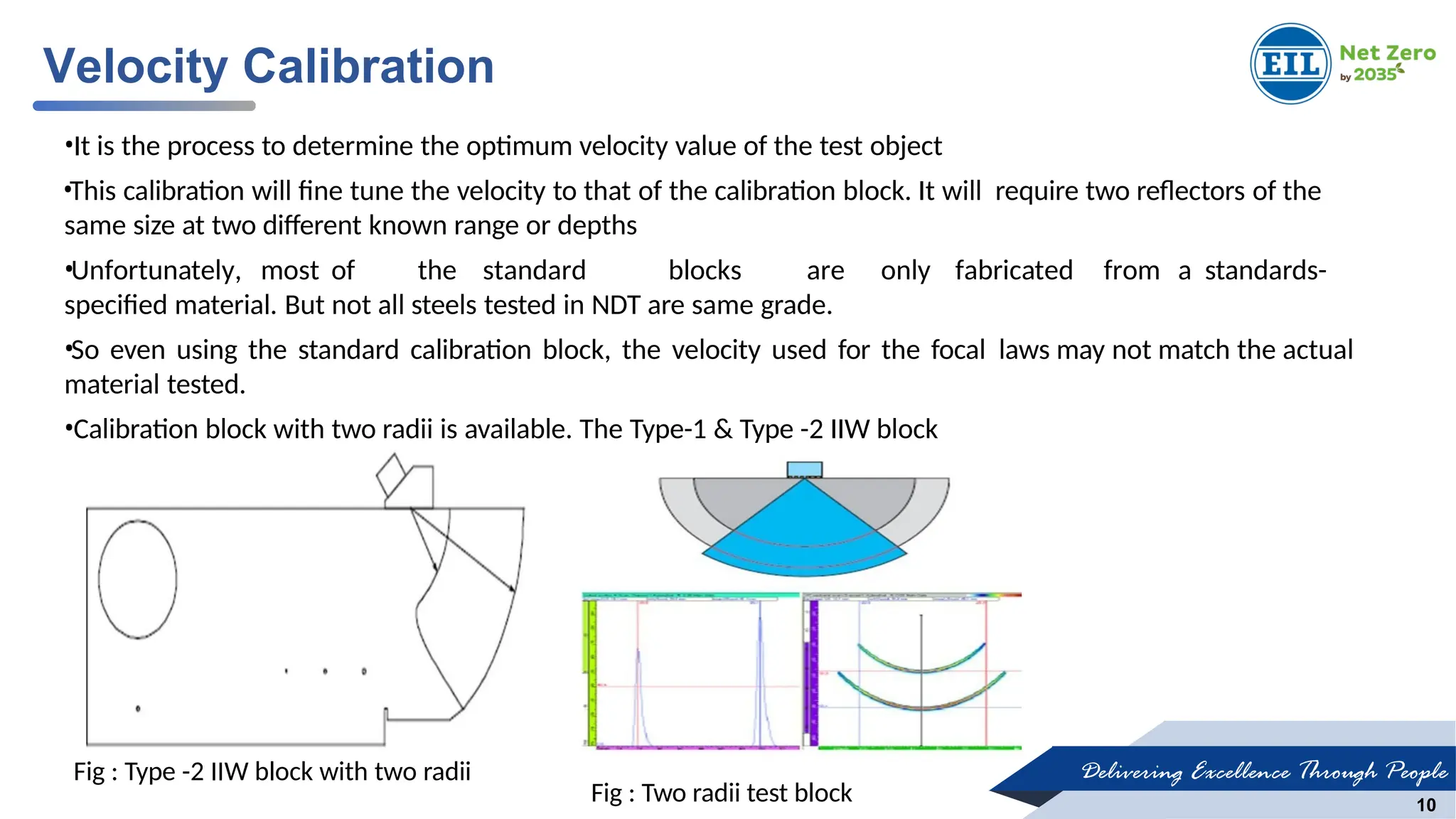
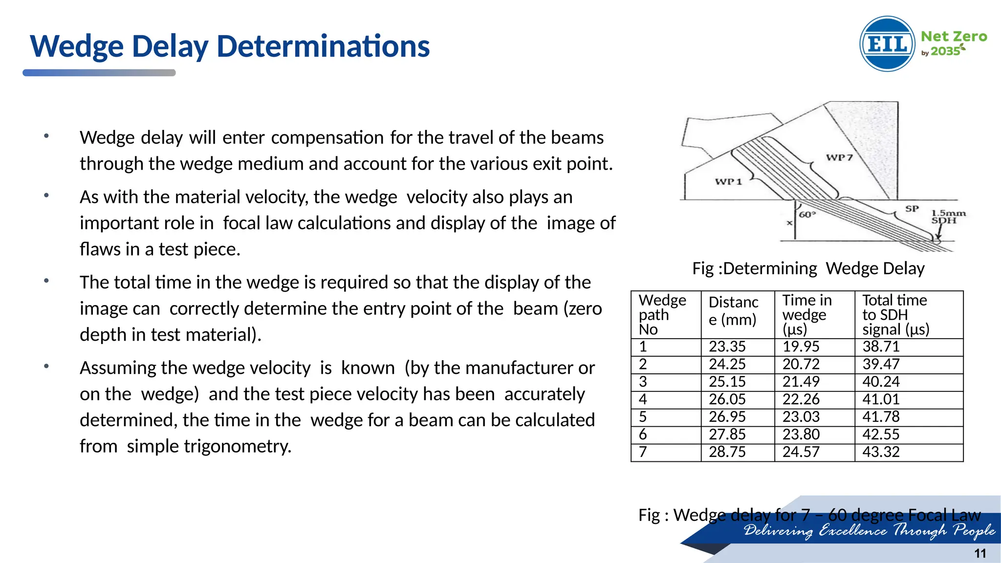
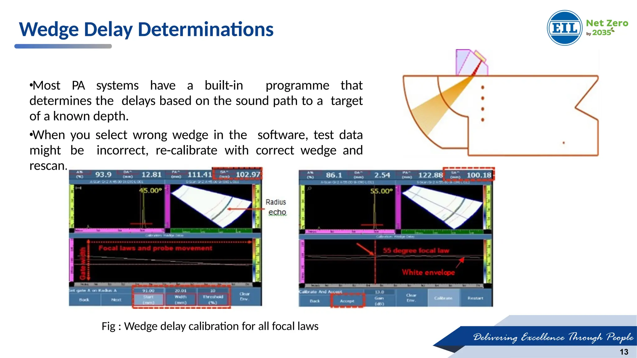
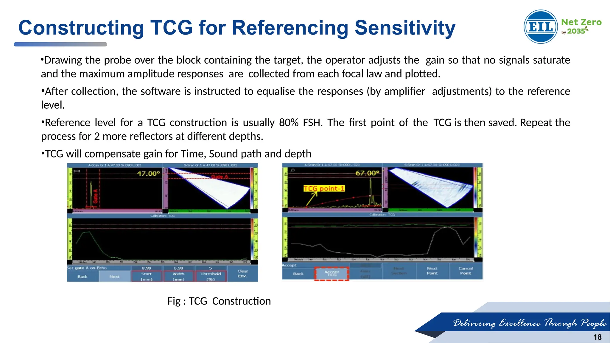
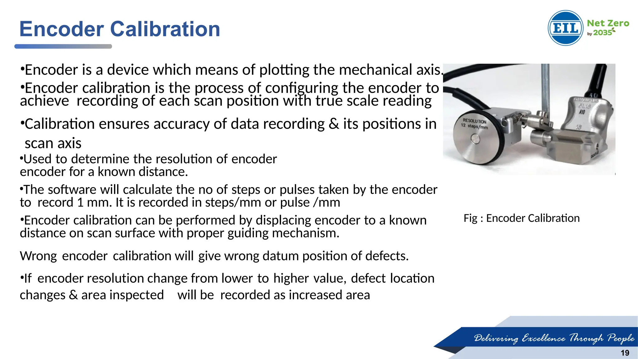
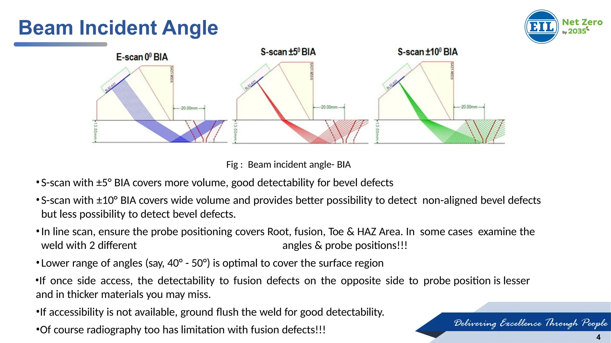
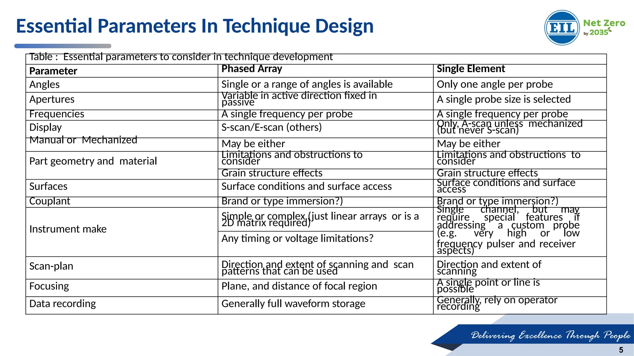
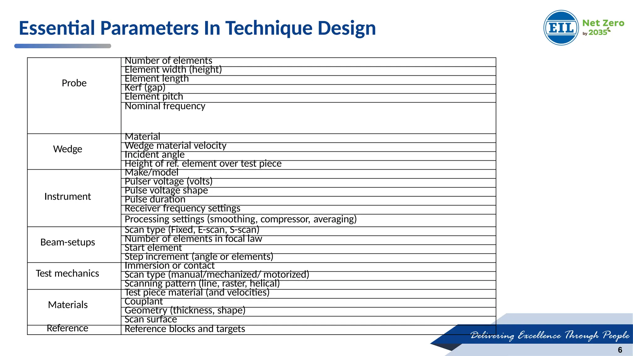
The document details the calibration procedures for Phased Array Ultrasonic Testing (PAUT) and Time of Flight Diffraction (TOFD), emphasizing parameters such as velocity, wedge delay, and sensitivity adjustments. It covers the importance of selecting appropriate angles and reference blocks for effective inspections, including considerations for welding regions and defect detection sensitivity. It also outlines the calibration steps necessary for accurate data recording and ensures the detection capabilities of inspection systems are optimized.

![Delivering Excellence Through People
9
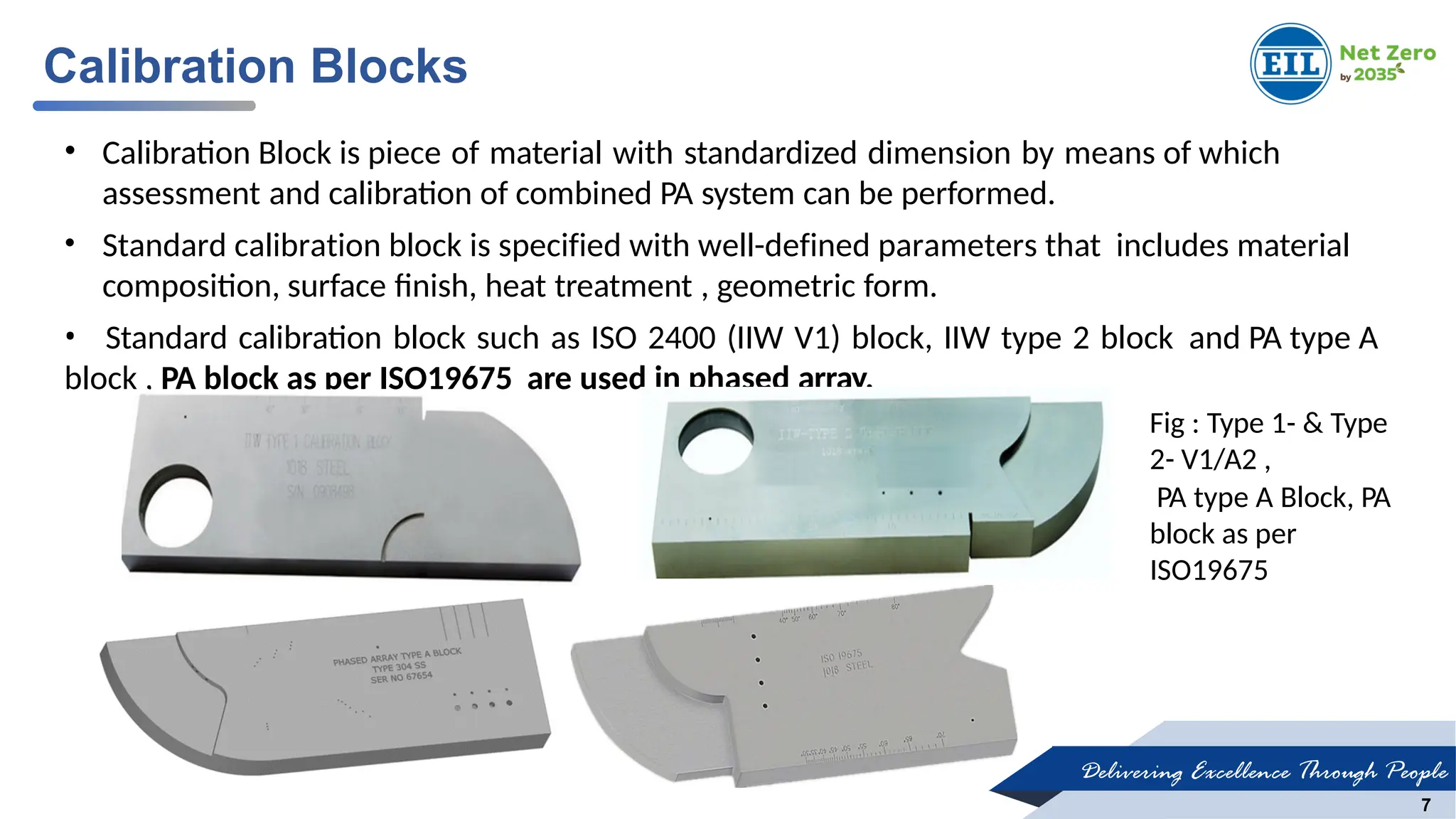
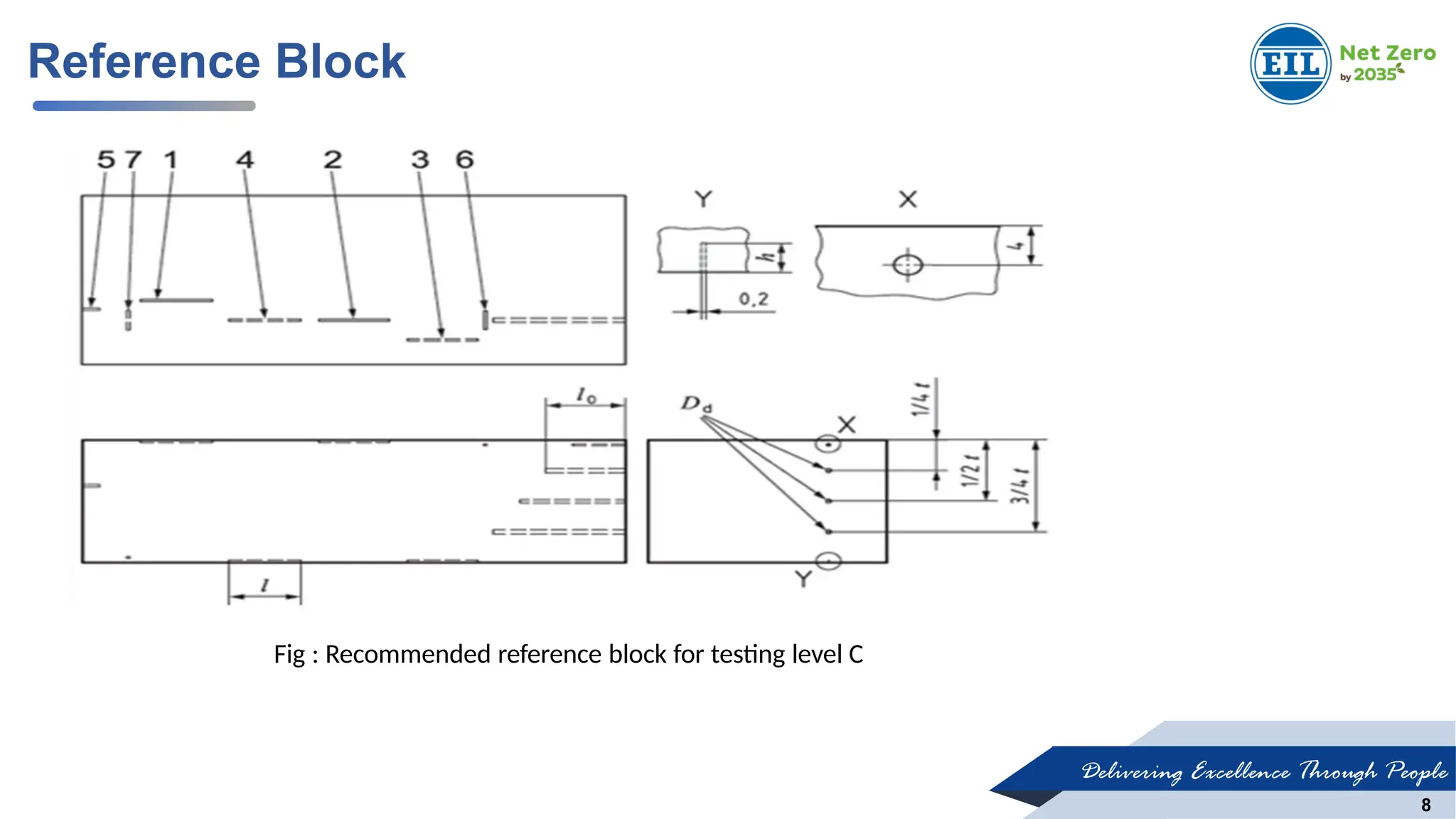
•Made with similar material (with regard to sound velocity, grain structure and surface condition) and shall consist of
well-defined reference reflectors.
•The length and width of the reference block is chosen such that all the reference reflectors can be properly scanned.
•In general SDH, Notch and FBH are used as typical reference reflector.
•The reference block, its length, width, depth of notches and length, depth , diameter of SDH are selected according
to the testing level required for the phased array inspection as per codes and standards.
Calibrations
The following Calibration process sequence involved in inspection setting.
1. Velocity calibration
2. Wedge delay calibration
3. Amplitude balancing (sensitivity calibration)
4. Time corrected gain [TCG]
5. Encoder calibration
Reference Block](https://image.slidesharecdn.com/calibration-pauttofd1-250123085833-d2a7f7fc/75/Calibration-of-Phased-array-UT-and-TOFD-1-pptx-9-2048.jpg)