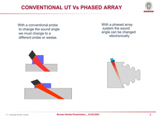
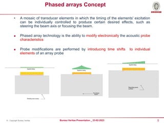
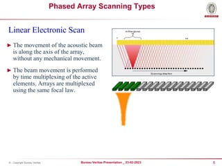
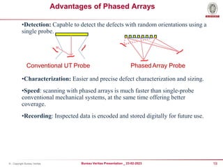
© - Copyright Bureau Veritas
PHASED ARRAY ULTRASONIC TESTING
22/07/2024
2
Bureau Veritas Presentation _ 23-02-2023
© - Copyright Bureau Veritas
CONVENTIONAL UT Vs PHASED ARRAY
With a conventional probe
to change the sound angle
we must change to a
different probe or wedge.
With a phased array
system the sound
angle can be changed
electronically
3
Bureau Veritas Presentation _ 23-02-2023
© - Copyright Bureau Veritas
CONVENTIONAL UT Vs PHASED ARRAY
To focus we must use a
lens or curved element.
To change the focus we
must change the probe.
The focal point can also
be changed electronically
4
Bureau Veritas Presentation _ 23-02-2023
© - Copyright Bureau Veritas
CONVENTIONAL UT Vs PHASED ARRAY
To scan the volume
of a part we must
physically move
the probe.
Physically movement of
the probe not required
to cover entire thickness
5
Bureau Veritas Presentation _ 23-02-2023
© - Copyright Bureau Veritas
Phased arrays Concept
• A mosaic of transducer elements in which the timing of the elements' excitation
can be individually controlled to produce certain desired effects, such as
steering the beam axis or focusing the beam.
 Phased array technology is the ability to modify electronically the acoustic probe
characteristics
 Probe modifications are performed by introducing time shifts to individual
elements of an array probe
6
Bureau Veritas Presentation _ 23-02-2023
© - Copyright Bureau Veritas
Phased Array Scanning Types
Linear Electronic Scan
► The movement of the acoustic beam
is along the axis of the array,
without any mechanical movement.
► The beam movement is performed
by time multiplexing of the active
elements. Arrays are multiplexed
using the same focal law.
7
Bureau Veritas Presentation _ 23-02-2023
© - Copyright Bureau Veritas
Phased Array Scanning Types
Sectorial Scan
► The ability to scan a complete sector
of volume without any probe
movement.
► Useful for inspection of complex
geometries, or geometries with
space restrictions.
► Combines the advantages of a wide
beam and/or multiple focused
probes in a single phased array
probe.
8
Bureau Veritas Presentation _ 23-02-2023
© - Copyright Bureau Veritas
Weld coverage
► Weld inspection
 PA probe in order to cover complete weld
volume.
 1 PA probe on each side of the weld
9
Bureau Veritas Presentation _ 23-02-2023
© - Copyright Bureau Veritas
Data Display
Traditional A-Scan (depth & amplitude)
S-Scan (Section view) Volumetric location, depth, height
C-Scan (Top view) Length, location, width
B-Scan (End view) Length, location, depth
10
Bureau Veritas Presentation _ 23-02-2023
© - Copyright Bureau Veritas
Defect Detection
Index axis
Scan axis
VC-TOP(C)
VIEW
Index axis
Scan axis
Top View
11
Bureau Veritas Presentation _ 23-02-2023
© - Copyright Bureau Veritas
Defect Detection
Index axis
Scan axis
VC-TOP(C)
VIEW
Index axis
Scan axis
Top View
12
Bureau Veritas Presentation _ 23-02-2023
© - Copyright Bureau Veritas
Defect Detection
13
Bureau Veritas Presentation _ 23-02-2023
© - Copyright Bureau Veritas
Defect Detection
CRACK
Radiography
Phased Array technique
14
Bureau Veritas Presentation _ 23-02-2023
© - Copyright Bureau Veritas
Defect Detection
LACK OF ROOT
PENETRATION
Radiography
Phased Array technique
15
Bureau Veritas Presentation _ 23-02-2023
© - Copyright Bureau Veritas
Defect Detection
SIDE WALL LACK
OF FUSION
Radiography
Phased Array technique
16
Bureau Veritas Presentation _ 23-02-2023
© - Copyright Bureau Veritas
Defect Detection
SLAG INCLUSIONS
Radiography
Phased Array technique
17
Bureau Veritas Presentation _ 23-02-2023
© - Copyright Bureau Veritas
Defect Detection
POROSITY Radiography
Phased Array technique
18
Bureau Veritas Presentation _ 23-02-2023
© - Copyright Bureau Veritas
Selection Of Scanners
Depends on the following job parameters
 Job type (Pipe / Vessel/plate)
 Job Conditions (Diameter & thickness of the pipe, accessibility)
 Scanning requirement (Semi automated / Manual)
19
Bureau Veritas Presentation _ 23-02-2023
© - Copyright Bureau Veritas
Advantages of Phased Arrays
•Detection: Capable to detect the defects with random orientations using a
single probe.
•Characterization: Easier and precise defect characterization and sizing.
•Speed: scanning with phased arrays is much faster than single-probe
conventional mechanical systems, at the same time offering better
coverage.
•Recording: Inspected data is encoded and stored digitally for future use.
Conventional UT Probe PhasedArray Probe
20
Bureau Veritas Presentation _ 23-02-2023
© - Copyright Bureau Veritas
Site Requirements
•20
•© - Copyright Bureau
► Client shall provide Job details (WPS, OD & Thickness details)
► Longitudinal or spiral welds must be ground flush a minimum of 250 mm on the
outside and a minimum of 100 mm on the ID side on each side of the weld from
circumferential weld (exact length to be defined).
► Neither coatings nor weld splatters are to be present up to (min) 250 mm on
either side of circumferential & longitudinal welds for the scanning area.
► Circumferential clearance between pipes shall be around 300 mm.
► Temperatures within 55 to 60 degree Celsius are acceptable.
► Clean, debris free fresh water for Inspection as couplant
► Facility to store our equipment and power to keep battery charging
21
Bureau Veritas Presentation _ 23-02-2023
© - Copyright Bureau Veritas

Phased array ultrasonic testing presentation

  • 1.
    © - CopyrightBureau Veritas PHASED ARRAY ULTRASONIC TESTING 22/07/2024
  • 2.
    2 Bureau Veritas Presentation_ 23-02-2023 © - Copyright Bureau Veritas CONVENTIONAL UT Vs PHASED ARRAY With a conventional probe to change the sound angle we must change to a different probe or wedge. With a phased array system the sound angle can be changed electronically
  • 3.
    3 Bureau Veritas Presentation_ 23-02-2023 © - Copyright Bureau Veritas CONVENTIONAL UT Vs PHASED ARRAY To focus we must use a lens or curved element. To change the focus we must change the probe. The focal point can also be changed electronically
  • 4.
    4 Bureau Veritas Presentation_ 23-02-2023 © - Copyright Bureau Veritas CONVENTIONAL UT Vs PHASED ARRAY To scan the volume of a part we must physically move the probe. Physically movement of the probe not required to cover entire thickness
  • 5.
    5 Bureau Veritas Presentation_ 23-02-2023 © - Copyright Bureau Veritas Phased arrays Concept • A mosaic of transducer elements in which the timing of the elements' excitation can be individually controlled to produce certain desired effects, such as steering the beam axis or focusing the beam.  Phased array technology is the ability to modify electronically the acoustic probe characteristics  Probe modifications are performed by introducing time shifts to individual elements of an array probe
  • 6.
    6 Bureau Veritas Presentation_ 23-02-2023 © - Copyright Bureau Veritas Phased Array Scanning Types Linear Electronic Scan ► The movement of the acoustic beam is along the axis of the array, without any mechanical movement. ► The beam movement is performed by time multiplexing of the active elements. Arrays are multiplexed using the same focal law.
  • 7.
    7 Bureau Veritas Presentation_ 23-02-2023 © - Copyright Bureau Veritas Phased Array Scanning Types Sectorial Scan ► The ability to scan a complete sector of volume without any probe movement. ► Useful for inspection of complex geometries, or geometries with space restrictions. ► Combines the advantages of a wide beam and/or multiple focused probes in a single phased array probe.
  • 8.
    8 Bureau Veritas Presentation_ 23-02-2023 © - Copyright Bureau Veritas Weld coverage ► Weld inspection  PA probe in order to cover complete weld volume.  1 PA probe on each side of the weld
  • 9.
    9 Bureau Veritas Presentation_ 23-02-2023 © - Copyright Bureau Veritas Data Display Traditional A-Scan (depth & amplitude) S-Scan (Section view) Volumetric location, depth, height C-Scan (Top view) Length, location, width B-Scan (End view) Length, location, depth
  • 10.
    10 Bureau Veritas Presentation_ 23-02-2023 © - Copyright Bureau Veritas Defect Detection Index axis Scan axis VC-TOP(C) VIEW Index axis Scan axis Top View
  • 11.
    11 Bureau Veritas Presentation_ 23-02-2023 © - Copyright Bureau Veritas Defect Detection Index axis Scan axis VC-TOP(C) VIEW Index axis Scan axis Top View
  • 12.
    12 Bureau Veritas Presentation_ 23-02-2023 © - Copyright Bureau Veritas Defect Detection
  • 13.
    13 Bureau Veritas Presentation_ 23-02-2023 © - Copyright Bureau Veritas Defect Detection CRACK Radiography Phased Array technique
  • 14.
    14 Bureau Veritas Presentation_ 23-02-2023 © - Copyright Bureau Veritas Defect Detection LACK OF ROOT PENETRATION Radiography Phased Array technique
  • 15.
    15 Bureau Veritas Presentation_ 23-02-2023 © - Copyright Bureau Veritas Defect Detection SIDE WALL LACK OF FUSION Radiography Phased Array technique
  • 16.
    16 Bureau Veritas Presentation_ 23-02-2023 © - Copyright Bureau Veritas Defect Detection SLAG INCLUSIONS Radiography Phased Array technique
  • 17.
    17 Bureau Veritas Presentation_ 23-02-2023 © - Copyright Bureau Veritas Defect Detection POROSITY Radiography Phased Array technique
  • 18.
    18 Bureau Veritas Presentation_ 23-02-2023 © - Copyright Bureau Veritas Selection Of Scanners Depends on the following job parameters  Job type (Pipe / Vessel/plate)  Job Conditions (Diameter & thickness of the pipe, accessibility)  Scanning requirement (Semi automated / Manual)
  • 19.
    19 Bureau Veritas Presentation_ 23-02-2023 © - Copyright Bureau Veritas Advantages of Phased Arrays •Detection: Capable to detect the defects with random orientations using a single probe. •Characterization: Easier and precise defect characterization and sizing. •Speed: scanning with phased arrays is much faster than single-probe conventional mechanical systems, at the same time offering better coverage. •Recording: Inspected data is encoded and stored digitally for future use. Conventional UT Probe PhasedArray Probe
  • 20.
    20 Bureau Veritas Presentation_ 23-02-2023 © - Copyright Bureau Veritas Site Requirements •20 •© - Copyright Bureau ► Client shall provide Job details (WPS, OD & Thickness details) ► Longitudinal or spiral welds must be ground flush a minimum of 250 mm on the outside and a minimum of 100 mm on the ID side on each side of the weld from circumferential weld (exact length to be defined). ► Neither coatings nor weld splatters are to be present up to (min) 250 mm on either side of circumferential & longitudinal welds for the scanning area. ► Circumferential clearance between pipes shall be around 300 mm. ► Temperatures within 55 to 60 degree Celsius are acceptable. ► Clean, debris free fresh water for Inspection as couplant ► Facility to store our equipment and power to keep battery charging
  • 21.
    21 Bureau Veritas Presentation_ 23-02-2023 © - Copyright Bureau Veritas