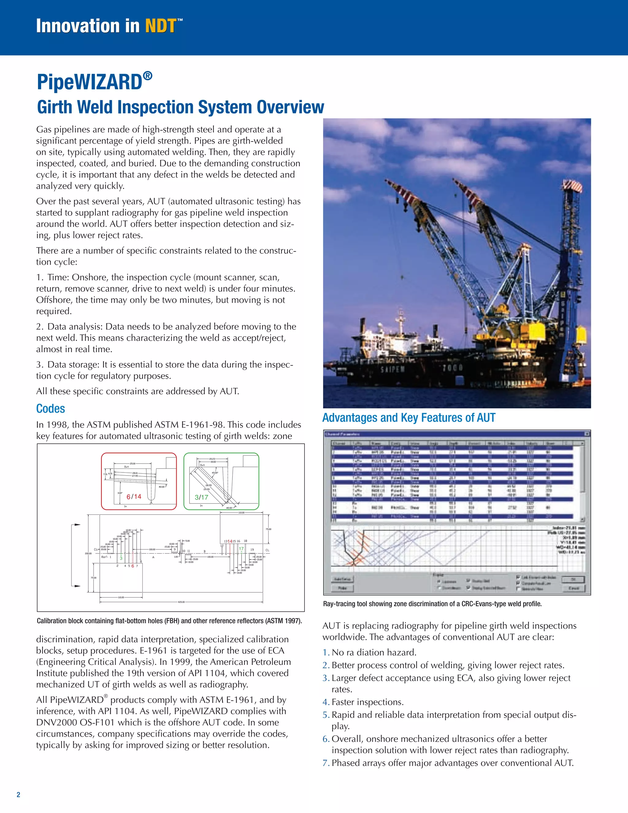
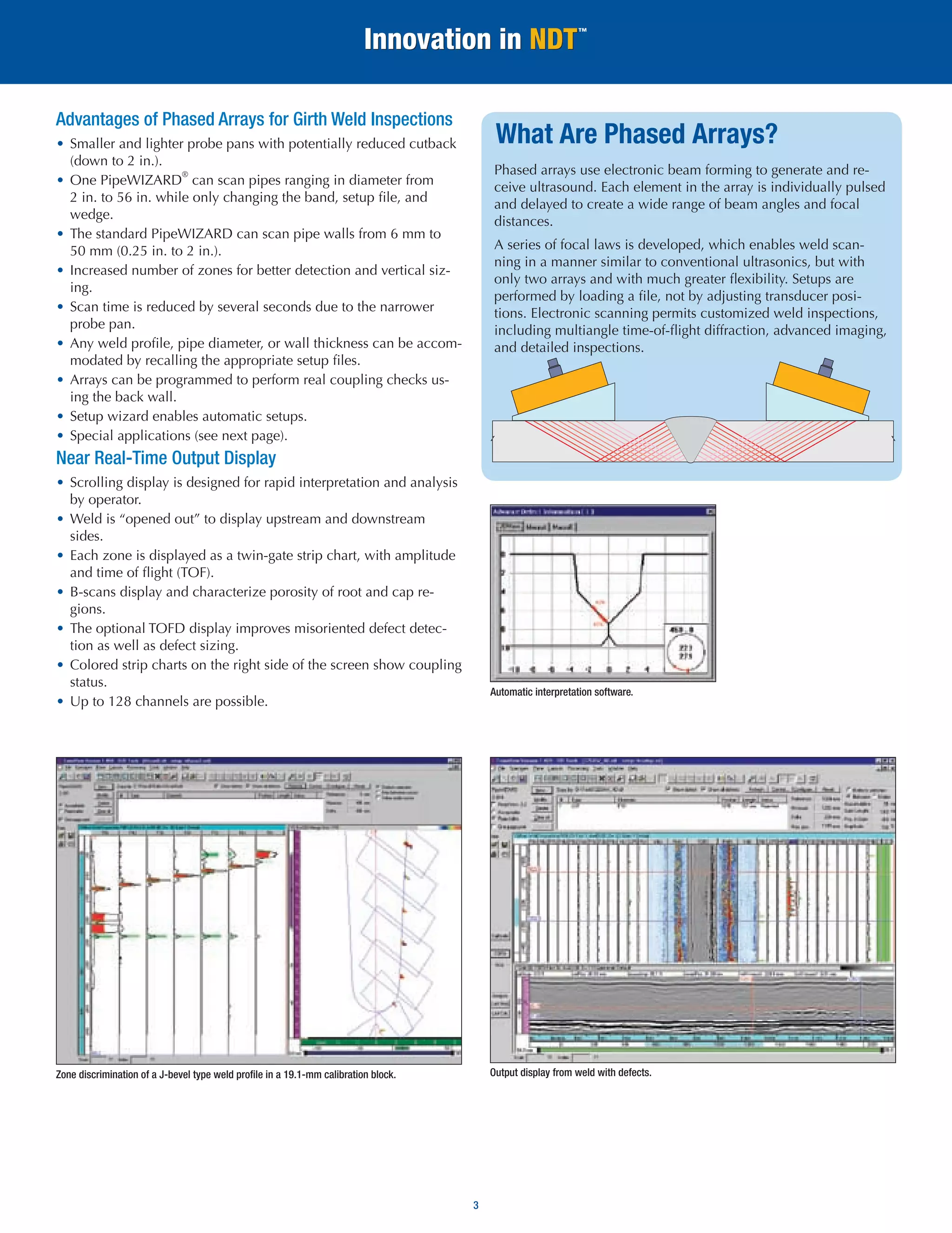
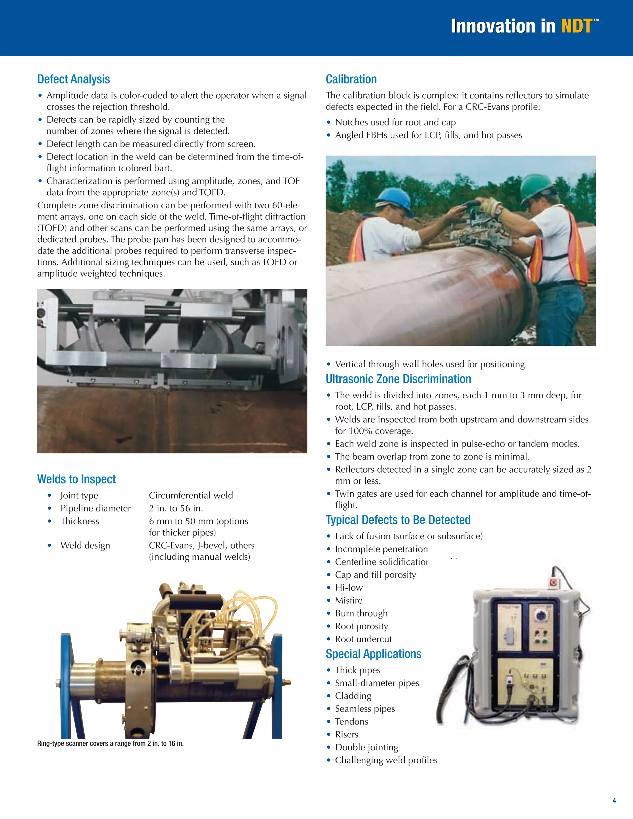
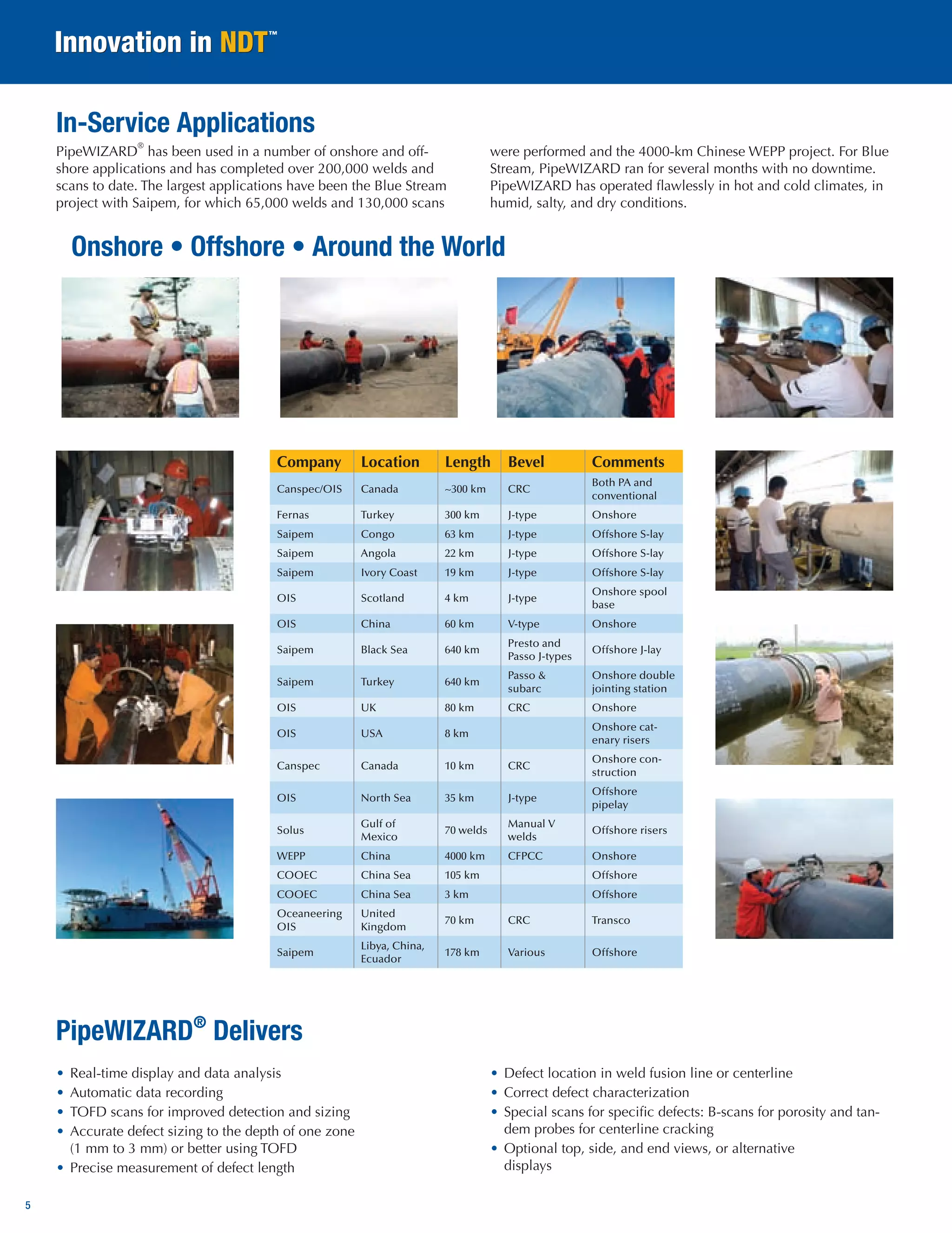
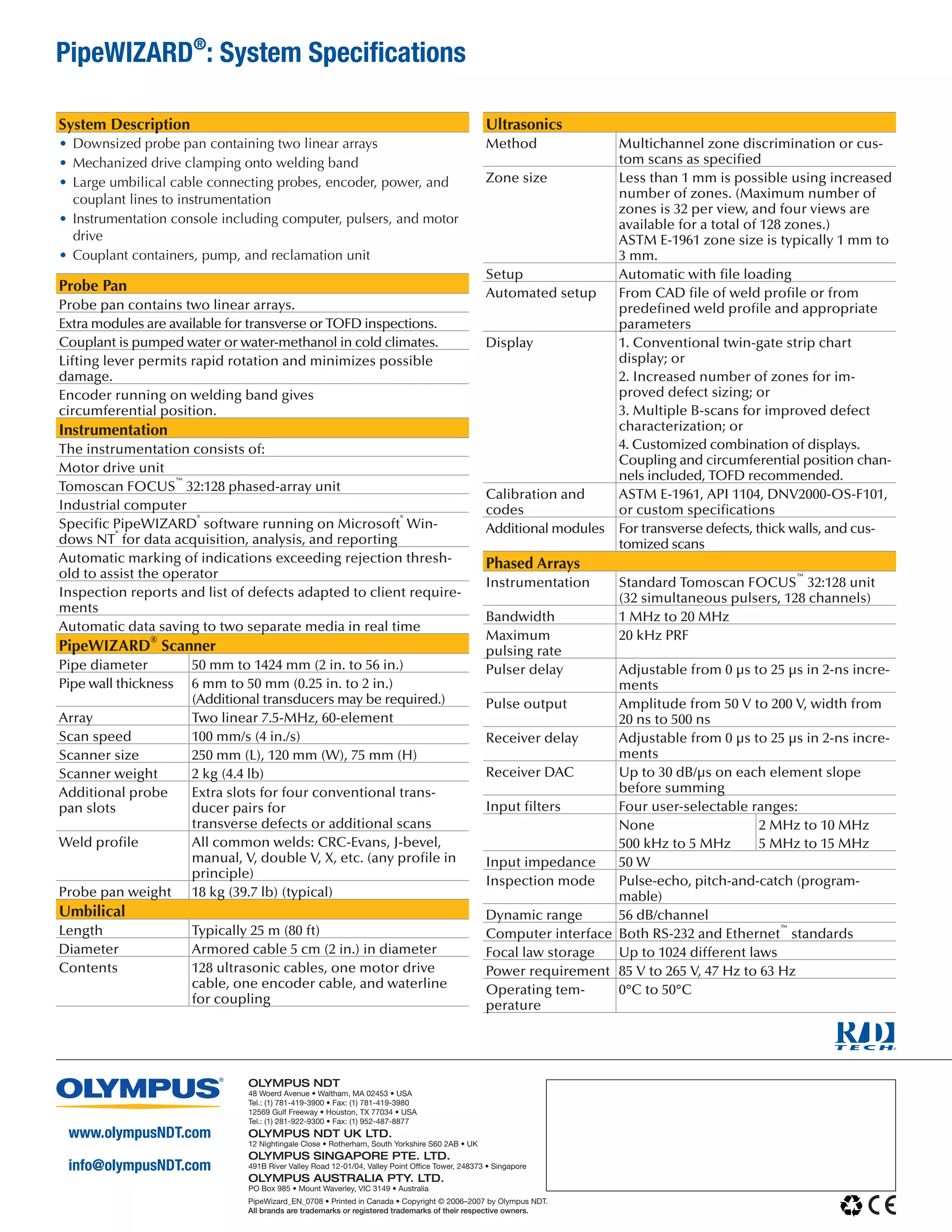
Meets or exceeds ASTM E-1961, DNV2000 OS-F101, and API 1104 codes 
PipeWIZARD® 
Automated ultrasonic inspection of pipeline girth welds using phased arrays 
• Fast scanning speed: 100 mm/s 
• Weld-to-weld inspection time of less than four minutes for 36-inch pipe 
• Very flexible for different pipe diameters, wall thicknesses, and weld profiles 
• Low operating costs 
• High reliability 
• “One size fits all” 
• Great for special scans
2 
Gas pipelines are made of high-strength steel and operate at a significant percentage of yield strength. Pipes are girth-welded on site, typically using automated welding. Then, they are rapidly inspected, coated, and buried. Due to the demanding construction cycle, it is important that any defect in the welds be detected and analyzed very quickly. 
Over the past several years, AUT (automated ultrasonic testing) has started to supplant radiography for gas pipeline weld inspection around the world. AUT offers better inspection detection and sizing, plus lower reject rates. 
There are a number of specific constraints related to the construction cycle: 
1. Time: Onshore, the inspection cycle (mount scanner, scan, return, remove scanner, drive to next weld) is under four minutes. Offshore, the time may only be two minutes, but moving is not required. 
2. Data analysis: Data needs to be analyzed before moving to the next weld. This means characterizing the weld as accept/reject, almost in real time. 
3. Data storage: It is essential to store the data during the inspection cycle for regulatory purposes. 
All these specific constraints are addressed by AUT. 
Codes 
In 1998, the ASTM published ASTM E-1961-98. This code includes key features for automated ultrasonic testing of girth welds: zone discrimination, rapid data interpretation, specialized calibration blocks, setup procedures. E-1961 is targeted for the use of ECA (Engineering Critical Analysis). In 1999, the American Petroleum Institute published the 19th version of API 1104, which covered mechanized UT of girth welds as well as radiography. 
All PipeWIZARD® products comply with ASTM E-1961, and by inference, with API 1104. As well, PipeWIZARD complies with DNV2000 OS-F101 which is the offshore AUT code. In some circumstances, company specifications may override the codes, typically by asking for improved sizing or better resolution. 
Advantages and Key Features of AUT 
AUT is replacing radiography for pipeline girth weld inspections worldwide. The advantages of conventional AUT are clear: 
1. No ra diation hazard. 
2. Better process control of welding, giving lower reject rates. 
3. Larger defect acceptance using ECA, also giving lower reject rates. 
4. Faster inspections. 
5. Rapid and reliable data interpretation from special output display. 
6. Overall, onshore mechanized ultrasonics offer a better 
inspection solution with lower reject rates than radiography. 
7. Phased arrays offer major advantages over conventional AUT. 
Calibration block containing flat-bottom holes (FBH) and other reference reflectors (ASTM 1997). 
Ray-tracing tool showing zone discrimination of a CRC-Evans-type weld profile. 
PipeWIZARD® 
Girth Weld Inspection System Overview
3 
What Are Phased Arrays? 
Phased arrays use electronic beam forming to generate and receive ultrasound. Each element in the array is individually pulsed and delayed to create a wide range of beam angles and focal distances. 
A series of focal laws is developed, which enables weld scanning in a manner similar to conventional ultrasonics, but with only two arrays and with much greater flexibility. Setups are performed by loading a file, not by adjusting transducer positions. Electronic scanning permits customized weld inspections, including multiangle time-of-flight diffraction, advanced imaging, and detailed inspections. 
Zone discrimination of a J-bevel type weld profile in a 19.1-mm calibration block. 
Output display from weld with defects. 
Automatic interpretation software. 
Advantages of Phased Arrays for Girth Weld Inspections 
• Smaller and lighter probe pans with potentially reduced cutback (down to 2 in.). 
• One PipeWIZARD® can scan pipes ranging in diameter from 2 in. to 56 in. while only changing the band, setup file, and wedge. 
• The standard PipeWIZARD can scan pipe walls from 6 mm to 50 mm (0.25 in. to 2 in.). 
• Increased number of zones for better detection and vertical sizing. 
• Scan time is reduced by several seconds due to the narrower probe pan. 
• Any weld profile, pipe diameter, or wall thickness can be accommodated by recalling the appropriate setup files. 
• Arrays can be programmed to perform real coupling checks using the back wall. 
• Setup wizard enables automatic setups. 
• Special applications (see next page). 
Near Real-Time Output Display 
• Scrolling display is designed for rapid interpretation and analysis by operator. 
• Weld is “opened out” to display upstream and downstream sides. 
• Each zone is displayed as a twin-gate strip chart, with amplitude and time of flight (TOF). 
• B-scans display and characterize porosity of root and cap regions. 
• The optional TOFD display improves misoriented defect detection as well as defect sizing. 
• Colored strip charts on the right side of the screen show coupling status. 
• Up to 128 channels are possible.
4 
Defect Analysis 
• Amplitude data is color-coded to alert the operator when a signal crosses the rejection threshold. 
• Defects can be rapidly sized by counting the 
number of zones where the signal is detected. 
• Defect length can be measured directly from screen. 
• Defect location in the weld can be determined from the time-of- flight information (colored bar). 
• Characterization is performed using amplitude, zones, and TOF data from the appropriate zone(s) and TOFD. 
Complete zone discrimination can be performed with two 60-element arrays, one on each side of the weld. Time-of-flight diffraction (TOFD) and other scans can be performed using the same arrays, or dedicated probes. The probe pan has been designed to accommodate the additional probes required to perform transverse inspections. Additional sizing techniques can be used, such as TOFD or amplitude weighted techniques. 
Welds to Inspect 
• Joint type Circumferential weld 
• Pipeline diameter 2 in. to 56 in. 
• Thickness 6 mm to 50 mm (options 
for thicker pipes) 
• Weld design CRC-Evans, J-bevel, others 
(including manual welds) 
Calibration 
The calibration block is complex: it contains reflectors to simulate defects expected in the field. For a CRC-Evans profile: 
• Notches used for root and cap 
• Angled FBHs used for LCP, fills, and hot passes 
• Vertical through-wall holes used for positioning 
Ultrasonic Zone Discrimination 
• The weld is divided into zones, each 1 mm to 3 mm deep, for root, LCP, fills, and hot passes. 
• Welds are inspected from both upstream and downstream sides for 100% coverage. 
• Each weld zone is inspected in pulse-echo or tandem modes. 
• The beam overlap from zone to zone is minimal. 
• Reflectors detected in a single zone can be accurately sized as 2 mm or less. 
• Twin gates are used for each channel for amplitude and time-of- flight. 
Typical Defects to Be Detected 
• Lack of fusion (surface or subsurface) 
• Incomplete penetration 
• Centerline solidification cracking 
• Cap and fill porosity 
• Hi-low 
• Misfire 
• Burn through 
• Root porosity 
• Root undercut 
Special Applications 
• Thick pipes 
• Small-diameter pipes 
• Cladding 
• Seamless pipes 
• Tendons 
• Risers 
• Double jointing 
• Challenging weld profiles 
Ring-type scanner covers a range from 2 in. to 16 in.
5 
PipeWIZARD® has been used in a number of onshore and offshore applications and has completed over 200,000 welds and scans to date. The largest applications have been the Blue Stream project with Saipem, for which 65,000 welds and 130,000 scans were performed and the 4000-km Chinese WEPP project. For Blue Stream, PipeWIZARD ran for several months with no downtime. PipeWIZARD has operated flawlessly in hot and cold climates, in humid, salty, and dry conditions. 
• Real-time display and data analysis 
• Automatic data recording 
• TOFD scans for improved detection and sizing 
• Accurate defect sizing to the depth of one zone 
(1 mm to 3 mm) or better using TOFD 
• Precise measurement of defect length 
• Defect location in weld fusion line or centerline 
• Correct defect characterization 
• Special scans for specific defects: B-scans for porosity and tandem probes for centerline cracking 
• Optional top, side, and end views, or alternative 
displays 
Onshore • Offshore • Around the World 
In-Service Applications 
Company 
Location 
Length 
Bevel 
Comments 
Canspec/OIS 
Canada 
~300 km 
CRC 
Both PA and conventional 
Fernas 
Turkey 
300 km 
J-type 
Onshore 
Saipem 
Congo 
63 km 
J-type 
Offshore S-lay 
Saipem 
Angola 
22 km 
J-type 
Offshore S-lay 
Saipem 
Ivory Coast 
19 km 
J-type 
Offshore S-lay 
OIS 
Scotland 
4 km 
J-type 
Onshore spool base 
OIS 
China 
60 km 
V-type 
Onshore 
Saipem 
Black Sea 
640 km 
Presto and Passo J-types 
Offshore J-lay 
Saipem 
Turkey 
640 km 
Passo & subarc 
Onshore double jointing station 
OIS 
UK 
80 km 
CRC 
Onshore 
OIS 
USA 
8 km 
Onshore catenary risers 
Canspec 
Canada 
10 km 
CRC 
Onshore construction 
OIS 
North Sea 
35 km 
J-type 
Offshore pipelay 
Solus 
Gulf of Mexico 
70 welds 
Manual V welds 
Offshore risers 
WEPP 
China 
4000 km 
CFPCC 
Onshore 
COOEC 
China Sea 
105 km 
Offshore 
COOEC 
China Sea 
3 km 
Offshore 
Oceaneering OIS 
United 
Kingdom 
70 km 
CRC 
Transco 
Saipem 
Libya, China, Ecuador 
178 km 
Various 
Offshore 
PipeWIZARD® Delivers
www.olympusNDT.com 
info@olympusNDT.com 
PipeWizard_EN_0708 • Printed in Canada • Copyright © 2006–2007 by Olympus NDT. 
All brands are trademarks or registered trademarks of their respective owners. 
Olympus NDT 
48 Woerd Avenue • Waltham, MA 02453 • USA 
Tel.: (1) 781-419-3900 • Fax: (1) 781-419-3980 
12569 Gulf Freeway • Houston, TX 77034 • USA 
Tel.: (1) 281-922-9300 • Fax: (1) 952-487-8877 
Olympus NDT UK LTD. 
12 Nightingale Close • Rotherham, South Yorkshire S60 2AB • UK 
Olympus Singapore PTE. LTD. 
491B River Valley Road 12-01/04, Valley Point Office Tower, 248373 • Singapore 
Olympus Australia PTY. LTD. 
PO Box 985 • Mount Waverley, VIC 3149 • Australia 
PipeWIZARD®: System Specifications 
System Description 
• Downsized probe pan containing two linear arrays 
• Mechanized drive clamping onto welding band 
• Large umbilical cable connecting probes, encoder, power, and couplant lines to instrumentation 
• Instrumentation console including computer, pulsers, and motor drive 
• Couplant containers, pump, and reclamation unit 
Probe Pan 
Probe pan contains two linear arrays. 
Extra modules are available for transverse or TOFD inspections. 
Couplant is pumped water or water-methanol in cold climates. 
Lifting lever permits rapid rotation and minimizes possible damage. 
Encoder running on welding band gives 
circumferential position. 
Instrumentation 
The instrumentation consists of: 
Motor drive unit 
Tomoscan FOCUS™ 32:128 phased-array unit 
Industrial computer 
Specific PipeWIZARD® software running on Microsoft® Windows NT® for data acquisition, analysis, and reporting 
Automatic marking of indications exceeding rejection threshold to assist the operator 
Inspection reports and list of defects adapted to client requirements 
Automatic data saving to two separate media in real time 
PipeWIZARD® Scanner 
Pipe diameter 
50 mm to 1424 mm (2 in. to 56 in.) 
Pipe wall thickness 
6 mm to 50 mm (0.25 in. to 2 in.) 
(Additional transducers may be required.) 
Array 
Two linear 7.5-MHz, 60-element 
Scan speed 
100 mm/s (4 in./s) 
Scanner size 
250 mm (L), 120 mm (W), 75 mm (H) 
Scanner weight 
2 kg (4.4 lb) 
Additional probe pan slots 
Extra slots for four conventional transducer pairs for 
transverse defects or additional scans 
Weld profile 
All common welds: CRC-Evans, J-bevel, manual, V, double V, X, etc. (any profile in principle) 
Probe pan weight 
18 kg (39.7 lb) (typical) 
Umbilical 
Length 
Typically 25 m (80 ft) 
Diameter 
Armored cable 5 cm (2 in.) in diameter 
Contents 
128 ultrasonic cables, one motor drive cable, one encoder cable, and waterline for coupling 
Ultrasonics 
Method 
Multichannel zone discrimination or custom scans as specified 
Zone size 
Less than 1 mm is possible using increased number of zones. (Maximum number of zones is 32 per view, and four views are available for a total of 128 zones.) 
ASTM E-1961 zone size is typically 1 mm to 3 mm. 
Setup 
Automatic with file loading 
Automated setup 
From CAD file of weld profile or from predefined weld profile and appropriate parameters 
Display 
1. Conventional twin-gate strip chart display; or 
2. Increased number of zones for improved defect sizing; or 
3. Multiple B-scans for improved defect characterization; or 
4. Customized combination of displays. Coupling and circumferential position channels included, TOFD recommended. 
Calibration and codes 
ASTM E-1961, API 1104, DNV2000-OS-F101, or custom specifications 
Additional modules 
For transverse defects, thick walls, and customized scans 
Phased Arrays 
Instrumentation 
Standard Tomoscan FOCUS™ 32:128 unit (32 simultaneous pulsers, 128 channels) 
Bandwidth 
1 MHz to 20 MHz 
Maximum 
pulsing rate 
20 kHz PRF 
Pulser delay 
Adjustable from 0 μs to 25 μs in 2-ns increments 
Pulse output 
Amplitude from 50 V to 200 V, width from 20 ns to 500 ns 
Receiver delay 
Adjustable from 0 μs to 25 μs in 2-ns increments 
Receiver DAC 
Up to 30 dB/μs on each element slope before summing 
Input filters 
Four user-selectable ranges: 
None 
500 kHz to 5 MHz 
2 MHz to 10 MHz 
5 MHz to 15 MHz 
Input impedance 
50 W 
Inspection mode 
Pulse-echo, pitch-and-catch (programmable) 
Dynamic range 
56 dB/channel 
Computer interface 
Both RS-232 and Ethernet™ standards 
Focal law storage 
Up to 1024 different laws 
Power requirement 
85 V to 265 V, 47 Hz to 63 Hz 
Operating temperature 
0°C to 50°C

Pipe wizard olympus

  • 1.
    Meets or exceedsASTM E-1961, DNV2000 OS-F101, and API 1104 codes PipeWIZARD® Automated ultrasonic inspection of pipeline girth welds using phased arrays • Fast scanning speed: 100 mm/s • Weld-to-weld inspection time of less than four minutes for 36-inch pipe • Very flexible for different pipe diameters, wall thicknesses, and weld profiles • Low operating costs • High reliability • “One size fits all” • Great for special scans
  • 2.
    2 Gas pipelinesare made of high-strength steel and operate at a significant percentage of yield strength. Pipes are girth-welded on site, typically using automated welding. Then, they are rapidly inspected, coated, and buried. Due to the demanding construction cycle, it is important that any defect in the welds be detected and analyzed very quickly. Over the past several years, AUT (automated ultrasonic testing) has started to supplant radiography for gas pipeline weld inspection around the world. AUT offers better inspection detection and sizing, plus lower reject rates. There are a number of specific constraints related to the construction cycle: 1. Time: Onshore, the inspection cycle (mount scanner, scan, return, remove scanner, drive to next weld) is under four minutes. Offshore, the time may only be two minutes, but moving is not required. 2. Data analysis: Data needs to be analyzed before moving to the next weld. This means characterizing the weld as accept/reject, almost in real time. 3. Data storage: It is essential to store the data during the inspection cycle for regulatory purposes. All these specific constraints are addressed by AUT. Codes In 1998, the ASTM published ASTM E-1961-98. This code includes key features for automated ultrasonic testing of girth welds: zone discrimination, rapid data interpretation, specialized calibration blocks, setup procedures. E-1961 is targeted for the use of ECA (Engineering Critical Analysis). In 1999, the American Petroleum Institute published the 19th version of API 1104, which covered mechanized UT of girth welds as well as radiography. All PipeWIZARD® products comply with ASTM E-1961, and by inference, with API 1104. As well, PipeWIZARD complies with DNV2000 OS-F101 which is the offshore AUT code. In some circumstances, company specifications may override the codes, typically by asking for improved sizing or better resolution. Advantages and Key Features of AUT AUT is replacing radiography for pipeline girth weld inspections worldwide. The advantages of conventional AUT are clear: 1. No ra diation hazard. 2. Better process control of welding, giving lower reject rates. 3. Larger defect acceptance using ECA, also giving lower reject rates. 4. Faster inspections. 5. Rapid and reliable data interpretation from special output display. 6. Overall, onshore mechanized ultrasonics offer a better inspection solution with lower reject rates than radiography. 7. Phased arrays offer major advantages over conventional AUT. Calibration block containing flat-bottom holes (FBH) and other reference reflectors (ASTM 1997). Ray-tracing tool showing zone discrimination of a CRC-Evans-type weld profile. PipeWIZARD® Girth Weld Inspection System Overview
  • 3.
    3 What ArePhased Arrays? Phased arrays use electronic beam forming to generate and receive ultrasound. Each element in the array is individually pulsed and delayed to create a wide range of beam angles and focal distances. A series of focal laws is developed, which enables weld scanning in a manner similar to conventional ultrasonics, but with only two arrays and with much greater flexibility. Setups are performed by loading a file, not by adjusting transducer positions. Electronic scanning permits customized weld inspections, including multiangle time-of-flight diffraction, advanced imaging, and detailed inspections. Zone discrimination of a J-bevel type weld profile in a 19.1-mm calibration block. Output display from weld with defects. Automatic interpretation software. Advantages of Phased Arrays for Girth Weld Inspections • Smaller and lighter probe pans with potentially reduced cutback (down to 2 in.). • One PipeWIZARD® can scan pipes ranging in diameter from 2 in. to 56 in. while only changing the band, setup file, and wedge. • The standard PipeWIZARD can scan pipe walls from 6 mm to 50 mm (0.25 in. to 2 in.). • Increased number of zones for better detection and vertical sizing. • Scan time is reduced by several seconds due to the narrower probe pan. • Any weld profile, pipe diameter, or wall thickness can be accommodated by recalling the appropriate setup files. • Arrays can be programmed to perform real coupling checks using the back wall. • Setup wizard enables automatic setups. • Special applications (see next page). Near Real-Time Output Display • Scrolling display is designed for rapid interpretation and analysis by operator. • Weld is “opened out” to display upstream and downstream sides. • Each zone is displayed as a twin-gate strip chart, with amplitude and time of flight (TOF). • B-scans display and characterize porosity of root and cap regions. • The optional TOFD display improves misoriented defect detection as well as defect sizing. • Colored strip charts on the right side of the screen show coupling status. • Up to 128 channels are possible.
  • 4.
    4 Defect Analysis • Amplitude data is color-coded to alert the operator when a signal crosses the rejection threshold. • Defects can be rapidly sized by counting the number of zones where the signal is detected. • Defect length can be measured directly from screen. • Defect location in the weld can be determined from the time-of- flight information (colored bar). • Characterization is performed using amplitude, zones, and TOF data from the appropriate zone(s) and TOFD. Complete zone discrimination can be performed with two 60-element arrays, one on each side of the weld. Time-of-flight diffraction (TOFD) and other scans can be performed using the same arrays, or dedicated probes. The probe pan has been designed to accommodate the additional probes required to perform transverse inspections. Additional sizing techniques can be used, such as TOFD or amplitude weighted techniques. Welds to Inspect • Joint type Circumferential weld • Pipeline diameter 2 in. to 56 in. • Thickness 6 mm to 50 mm (options for thicker pipes) • Weld design CRC-Evans, J-bevel, others (including manual welds) Calibration The calibration block is complex: it contains reflectors to simulate defects expected in the field. For a CRC-Evans profile: • Notches used for root and cap • Angled FBHs used for LCP, fills, and hot passes • Vertical through-wall holes used for positioning Ultrasonic Zone Discrimination • The weld is divided into zones, each 1 mm to 3 mm deep, for root, LCP, fills, and hot passes. • Welds are inspected from both upstream and downstream sides for 100% coverage. • Each weld zone is inspected in pulse-echo or tandem modes. • The beam overlap from zone to zone is minimal. • Reflectors detected in a single zone can be accurately sized as 2 mm or less. • Twin gates are used for each channel for amplitude and time-of- flight. Typical Defects to Be Detected • Lack of fusion (surface or subsurface) • Incomplete penetration • Centerline solidification cracking • Cap and fill porosity • Hi-low • Misfire • Burn through • Root porosity • Root undercut Special Applications • Thick pipes • Small-diameter pipes • Cladding • Seamless pipes • Tendons • Risers • Double jointing • Challenging weld profiles Ring-type scanner covers a range from 2 in. to 16 in.
  • 5.
    5 PipeWIZARD® hasbeen used in a number of onshore and offshore applications and has completed over 200,000 welds and scans to date. The largest applications have been the Blue Stream project with Saipem, for which 65,000 welds and 130,000 scans were performed and the 4000-km Chinese WEPP project. For Blue Stream, PipeWIZARD ran for several months with no downtime. PipeWIZARD has operated flawlessly in hot and cold climates, in humid, salty, and dry conditions. • Real-time display and data analysis • Automatic data recording • TOFD scans for improved detection and sizing • Accurate defect sizing to the depth of one zone (1 mm to 3 mm) or better using TOFD • Precise measurement of defect length • Defect location in weld fusion line or centerline • Correct defect characterization • Special scans for specific defects: B-scans for porosity and tandem probes for centerline cracking • Optional top, side, and end views, or alternative displays Onshore • Offshore • Around the World In-Service Applications Company Location Length Bevel Comments Canspec/OIS Canada ~300 km CRC Both PA and conventional Fernas Turkey 300 km J-type Onshore Saipem Congo 63 km J-type Offshore S-lay Saipem Angola 22 km J-type Offshore S-lay Saipem Ivory Coast 19 km J-type Offshore S-lay OIS Scotland 4 km J-type Onshore spool base OIS China 60 km V-type Onshore Saipem Black Sea 640 km Presto and Passo J-types Offshore J-lay Saipem Turkey 640 km Passo & subarc Onshore double jointing station OIS UK 80 km CRC Onshore OIS USA 8 km Onshore catenary risers Canspec Canada 10 km CRC Onshore construction OIS North Sea 35 km J-type Offshore pipelay Solus Gulf of Mexico 70 welds Manual V welds Offshore risers WEPP China 4000 km CFPCC Onshore COOEC China Sea 105 km Offshore COOEC China Sea 3 km Offshore Oceaneering OIS United Kingdom 70 km CRC Transco Saipem Libya, China, Ecuador 178 km Various Offshore PipeWIZARD® Delivers
  • 6.
    www.olympusNDT.com info@olympusNDT.com PipeWizard_EN_0708• Printed in Canada • Copyright © 2006–2007 by Olympus NDT. All brands are trademarks or registered trademarks of their respective owners. Olympus NDT 48 Woerd Avenue • Waltham, MA 02453 • USA Tel.: (1) 781-419-3900 • Fax: (1) 781-419-3980 12569 Gulf Freeway • Houston, TX 77034 • USA Tel.: (1) 281-922-9300 • Fax: (1) 952-487-8877 Olympus NDT UK LTD. 12 Nightingale Close • Rotherham, South Yorkshire S60 2AB • UK Olympus Singapore PTE. LTD. 491B River Valley Road 12-01/04, Valley Point Office Tower, 248373 • Singapore Olympus Australia PTY. LTD. PO Box 985 • Mount Waverley, VIC 3149 • Australia PipeWIZARD®: System Specifications System Description • Downsized probe pan containing two linear arrays • Mechanized drive clamping onto welding band • Large umbilical cable connecting probes, encoder, power, and couplant lines to instrumentation • Instrumentation console including computer, pulsers, and motor drive • Couplant containers, pump, and reclamation unit Probe Pan Probe pan contains two linear arrays. Extra modules are available for transverse or TOFD inspections. Couplant is pumped water or water-methanol in cold climates. Lifting lever permits rapid rotation and minimizes possible damage. Encoder running on welding band gives circumferential position. Instrumentation The instrumentation consists of: Motor drive unit Tomoscan FOCUS™ 32:128 phased-array unit Industrial computer Specific PipeWIZARD® software running on Microsoft® Windows NT® for data acquisition, analysis, and reporting Automatic marking of indications exceeding rejection threshold to assist the operator Inspection reports and list of defects adapted to client requirements Automatic data saving to two separate media in real time PipeWIZARD® Scanner Pipe diameter 50 mm to 1424 mm (2 in. to 56 in.) Pipe wall thickness 6 mm to 50 mm (0.25 in. to 2 in.) (Additional transducers may be required.) Array Two linear 7.5-MHz, 60-element Scan speed 100 mm/s (4 in./s) Scanner size 250 mm (L), 120 mm (W), 75 mm (H) Scanner weight 2 kg (4.4 lb) Additional probe pan slots Extra slots for four conventional transducer pairs for transverse defects or additional scans Weld profile All common welds: CRC-Evans, J-bevel, manual, V, double V, X, etc. (any profile in principle) Probe pan weight 18 kg (39.7 lb) (typical) Umbilical Length Typically 25 m (80 ft) Diameter Armored cable 5 cm (2 in.) in diameter Contents 128 ultrasonic cables, one motor drive cable, one encoder cable, and waterline for coupling Ultrasonics Method Multichannel zone discrimination or custom scans as specified Zone size Less than 1 mm is possible using increased number of zones. (Maximum number of zones is 32 per view, and four views are available for a total of 128 zones.) ASTM E-1961 zone size is typically 1 mm to 3 mm. Setup Automatic with file loading Automated setup From CAD file of weld profile or from predefined weld profile and appropriate parameters Display 1. Conventional twin-gate strip chart display; or 2. Increased number of zones for improved defect sizing; or 3. Multiple B-scans for improved defect characterization; or 4. Customized combination of displays. Coupling and circumferential position channels included, TOFD recommended. Calibration and codes ASTM E-1961, API 1104, DNV2000-OS-F101, or custom specifications Additional modules For transverse defects, thick walls, and customized scans Phased Arrays Instrumentation Standard Tomoscan FOCUS™ 32:128 unit (32 simultaneous pulsers, 128 channels) Bandwidth 1 MHz to 20 MHz Maximum pulsing rate 20 kHz PRF Pulser delay Adjustable from 0 μs to 25 μs in 2-ns increments Pulse output Amplitude from 50 V to 200 V, width from 20 ns to 500 ns Receiver delay Adjustable from 0 μs to 25 μs in 2-ns increments Receiver DAC Up to 30 dB/μs on each element slope before summing Input filters Four user-selectable ranges: None 500 kHz to 5 MHz 2 MHz to 10 MHz 5 MHz to 15 MHz Input impedance 50 W Inspection mode Pulse-echo, pitch-and-catch (programmable) Dynamic range 56 dB/channel Computer interface Both RS-232 and Ethernet™ standards Focal law storage Up to 1024 different laws Power requirement 85 V to 265 V, 47 Hz to 63 Hz Operating temperature 0°C to 50°C