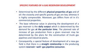
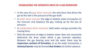
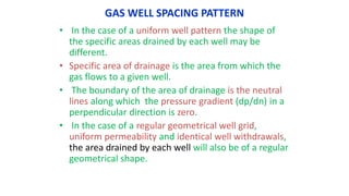
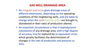
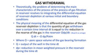
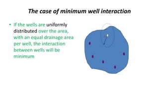
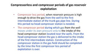
GAS FIELD DEVELOPMENT
BASIC PRICIPLES AND PLANNING
SPECIFIC FEATURES OF A GAS RESERVOIR DEVELOPMENT
• Determined by the different physical properties of gas and of
oil: the viscosity and specific gravity of gas are low, whereas it
is highly compressible. Moreover, gas differs from oil in it’s
commercial properties.
• The base reference value in planning the development of a
gas reservoir is the daily output which is determined by the
demand for gas at the particular time. The planned rate of
increase of gas production from a given reservoir may be
determined by the plans for the construction of trunk gas
pipelines and industrial plants.
• Consequently, a special feature of development of a new gas
field is that there is a straight relationship in the producing
system reservoir –well –gas pipeline-consumer.
ESTABLISHING THE OPERATIVE DRIVE OF A GAS RESERVOIR
• In the case of a gas drive reservoir, the only force that drives the
gas to the well is the pressure of the gas itself.
• In water drive reservoir the edge or bottom water encroaches on
the reservoir and displaces the gas, making up for the loss of
pressure.
• In combination drive reservoirs, both water and gas provides the
moving force
• Only the presence of edge or bottom water does not necessarily
determine the drive under which a gas reservoir operates.
Between the gas bearing zone and the water there may be
impervious sections of formation, or as the water encroaches, a
chemical barrier may be formed that hinders its further advance
GAS WELL SPACING PATTERN
• In the case of a uniform well pattern the shape of
the specific areas drained by each well may be
different.
• Specific area of drainage is the area from which the
gas flows to a given well.
• The boundary of the area of drainage is the neutral
lines along which the pressure gradient (dp/dn) in a
perpendicular direction is zero.
• In the case of a regular geometrical well grid,
uniform permeability and identical well withdrawals,
the area drained by each well will also be of a regular
geometrical shape.
GAS WELL DRAINAGE AREA
• An irregular well array gives drainage areas of
different dimensions, depending on the operating
conditions of the neighboring wells, and are liable to
change when the latter(nearby wells) are brought in,
abandoned or their rates of production altered.
• An important circumstance is that in hydrodynamic
calculations of any drainage area, with a high degree
of accuracy, may be replaced by an equivalent circle,
which greatly facilitates the determination of
changes in the rate of production and pressure vs.
time.
GAS WITHDRAWAL
• Theoretically, the problem of determining the main
characteristics of the process of the process of gas filtration
in reservoir resolves to integrating the differential equation
of reservoir depletion at various initial and boundary
conditions
• The physical meaning of the differential equation of the gas
reservoir depletion is that the quantity of gas withdrawn
over a certain time interval dt is equal to the reduction in
the reserve of the gas in the reservoir Ωdp/dt: (Read Ω as omega)
Q dt = -Ω dp/Patm
• Where Ω = pore space volume of the gas bearing formation
• Q = output of the well in the time dt
• dp= reduction in mean weighted pressure in the reservoir
during the time dt
The case of minimum well interaction
• If the wells are uniformly
distributed over the area,
with an equal drainage area
per well, the interaction
between wells will be
minimum
rb
The case of maximum well interaction
• Interaction between
wells is maximum when
they are concentrated
on a small section of
reservoir with pore
space volume Ω,
assuming that the wells
are situated at the
center of the reservoir
in the form of a circular
battery with a small
radius Rb
Lcir
Rb
Compressorless and compressor periods of gas reservoir
exploitation
• Compressor less period, when reservoir pressure is high
enough to drive the gas from the well to the first
intermediate station of the trunk gas pipe line. During
this period no head compressor station is needed.
• The compressor period during which gas from the well
moves under its own pressure only to the intake of the
head compressor station located near the wells. From the
head compressor station the gas is delivered to the intake
of the first intermediate station. Construction of the
compressor station in the gas field should be completed
by the time the first compressor less period of
exploitation is over.
ECONOMICS OF OIL AND GAS FIELD
DEVELOPMENT
• In planning a reservoir development system factors
such as well and rows patterns are considered.
• The well spacing of one hectre per well in a non-
homogenous solution gas drive reservoir is known;
• whereas up to 60 hectres per well in a homogenous
water drive reservoir may be used.
• It is generally recommended to have a wide spacing
in the beginning so that a good idea of the reservoir
is obtained and to finalise the spacing of the
planned wells.
ECONOMICS OF OIL AND GAS FIELD DEVELOPMENT
• In order to select the final variant of development
plan various alternatives should be worked out to
establish the one that offers the biggest economic
and technological advantages.
• The main factors for the reservoir development
efficiency are as follows-
 The rate of development needed to meet the
rational demand for oil & gas.
 Oil recovery factor (ultimate oil recovery /
original oil)
 Material & labour cost.
PRODUCTIVE LIFE OF A RESERVOIR
The productive life of a reservoir is a function of the
following:-
The planned rational rate of oil production increase.
Geological, technical and economic condition of a given
reservoir.
The amount of prospected results, their geological
location and readiness for development.
Oil & gas reserve.
The technological level of oil production.
By using pressure maintenance methods, such as,
water injection and gas injection the productive life can
be shortened and higher withdrawal maintained.
Oil Recovery Factor
• In heterogeneous reservoir, the oil recovery
factor increases with closer spacing. This
however increases development costs.
• Recovery of oil up to 60 – 80% is obtained
with the help of modern development
methods.
• The water drive reservoirs give higher
recovery factor compared to gas cap drive
and depletion drive reservoir.
MATERIAL AND LABOUR COSTS
In formulating the economic characteristics of different
development plans, the following factors are used:
Labour productivity.
Capital investment.
Operating cost.
Production cost.
Labour cost consists of following:-
Drilling labour cost.
Oil filed operation labour cost
Pressure maintenance labour cost
Auxiliary department operation labour cost, such as electrical,
mechanical, water supply, services department and other utility.
Construction and erection department labour costs.
O
V
E
R

Oil and gas field development

  • 1.
    GAS FIELD DEVELOPMENT BASICPRICIPLES AND PLANNING
  • 2.
    SPECIFIC FEATURES OFA GAS RESERVOIR DEVELOPMENT • Determined by the different physical properties of gas and of oil: the viscosity and specific gravity of gas are low, whereas it is highly compressible. Moreover, gas differs from oil in it’s commercial properties. • The base reference value in planning the development of a gas reservoir is the daily output which is determined by the demand for gas at the particular time. The planned rate of increase of gas production from a given reservoir may be determined by the plans for the construction of trunk gas pipelines and industrial plants. • Consequently, a special feature of development of a new gas field is that there is a straight relationship in the producing system reservoir –well –gas pipeline-consumer.
  • 3.
    ESTABLISHING THE OPERATIVEDRIVE OF A GAS RESERVOIR • In the case of a gas drive reservoir, the only force that drives the gas to the well is the pressure of the gas itself. • In water drive reservoir the edge or bottom water encroaches on the reservoir and displaces the gas, making up for the loss of pressure. • In combination drive reservoirs, both water and gas provides the moving force • Only the presence of edge or bottom water does not necessarily determine the drive under which a gas reservoir operates. Between the gas bearing zone and the water there may be impervious sections of formation, or as the water encroaches, a chemical barrier may be formed that hinders its further advance
  • 4.
    GAS WELL SPACINGPATTERN • In the case of a uniform well pattern the shape of the specific areas drained by each well may be different. • Specific area of drainage is the area from which the gas flows to a given well. • The boundary of the area of drainage is the neutral lines along which the pressure gradient (dp/dn) in a perpendicular direction is zero. • In the case of a regular geometrical well grid, uniform permeability and identical well withdrawals, the area drained by each well will also be of a regular geometrical shape.
  • 5.
    GAS WELL DRAINAGEAREA • An irregular well array gives drainage areas of different dimensions, depending on the operating conditions of the neighboring wells, and are liable to change when the latter(nearby wells) are brought in, abandoned or their rates of production altered. • An important circumstance is that in hydrodynamic calculations of any drainage area, with a high degree of accuracy, may be replaced by an equivalent circle, which greatly facilitates the determination of changes in the rate of production and pressure vs. time.
  • 6.
    GAS WITHDRAWAL • Theoretically,the problem of determining the main characteristics of the process of the process of gas filtration in reservoir resolves to integrating the differential equation of reservoir depletion at various initial and boundary conditions • The physical meaning of the differential equation of the gas reservoir depletion is that the quantity of gas withdrawn over a certain time interval dt is equal to the reduction in the reserve of the gas in the reservoir Ωdp/dt: (Read Ω as omega) Q dt = -Ω dp/Patm • Where Ω = pore space volume of the gas bearing formation • Q = output of the well in the time dt • dp= reduction in mean weighted pressure in the reservoir during the time dt
  • 7.
    The case ofminimum well interaction • If the wells are uniformly distributed over the area, with an equal drainage area per well, the interaction between wells will be minimum rb
  • 8.
    The case ofmaximum well interaction • Interaction between wells is maximum when they are concentrated on a small section of reservoir with pore space volume Ω, assuming that the wells are situated at the center of the reservoir in the form of a circular battery with a small radius Rb Lcir Rb
  • 9.
    Compressorless and compressorperiods of gas reservoir exploitation • Compressor less period, when reservoir pressure is high enough to drive the gas from the well to the first intermediate station of the trunk gas pipe line. During this period no head compressor station is needed. • The compressor period during which gas from the well moves under its own pressure only to the intake of the head compressor station located near the wells. From the head compressor station the gas is delivered to the intake of the first intermediate station. Construction of the compressor station in the gas field should be completed by the time the first compressor less period of exploitation is over.
  • 10.
    ECONOMICS OF OILAND GAS FIELD DEVELOPMENT • In planning a reservoir development system factors such as well and rows patterns are considered. • The well spacing of one hectre per well in a non- homogenous solution gas drive reservoir is known; • whereas up to 60 hectres per well in a homogenous water drive reservoir may be used. • It is generally recommended to have a wide spacing in the beginning so that a good idea of the reservoir is obtained and to finalise the spacing of the planned wells.
  • 11.
    ECONOMICS OF OILAND GAS FIELD DEVELOPMENT • In order to select the final variant of development plan various alternatives should be worked out to establish the one that offers the biggest economic and technological advantages. • The main factors for the reservoir development efficiency are as follows-  The rate of development needed to meet the rational demand for oil & gas.  Oil recovery factor (ultimate oil recovery / original oil)  Material & labour cost.
  • 12.
    PRODUCTIVE LIFE OFA RESERVOIR The productive life of a reservoir is a function of the following:- The planned rational rate of oil production increase. Geological, technical and economic condition of a given reservoir. The amount of prospected results, their geological location and readiness for development. Oil & gas reserve. The technological level of oil production. By using pressure maintenance methods, such as, water injection and gas injection the productive life can be shortened and higher withdrawal maintained.
  • 13.
    Oil Recovery Factor •In heterogeneous reservoir, the oil recovery factor increases with closer spacing. This however increases development costs. • Recovery of oil up to 60 – 80% is obtained with the help of modern development methods. • The water drive reservoirs give higher recovery factor compared to gas cap drive and depletion drive reservoir.
  • 14.
    MATERIAL AND LABOURCOSTS In formulating the economic characteristics of different development plans, the following factors are used: Labour productivity. Capital investment. Operating cost. Production cost. Labour cost consists of following:- Drilling labour cost. Oil filed operation labour cost Pressure maintenance labour cost Auxiliary department operation labour cost, such as electrical, mechanical, water supply, services department and other utility. Construction and erection department labour costs.
  • 15.