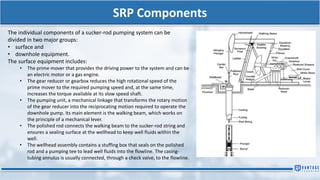
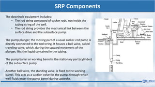
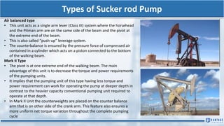
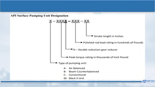
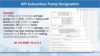
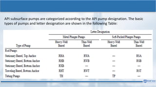
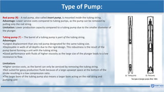
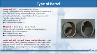
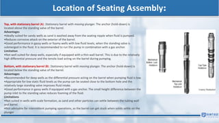
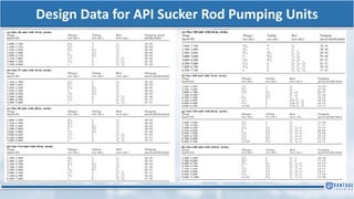
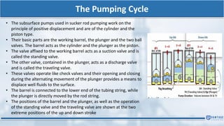
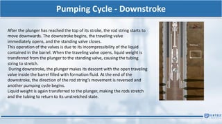
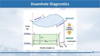
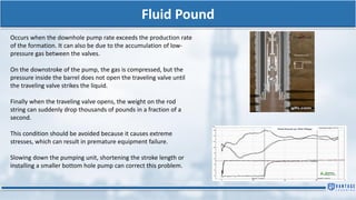
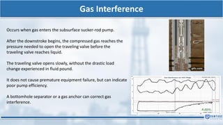
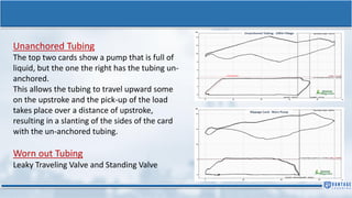
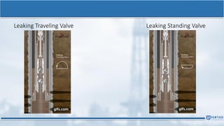
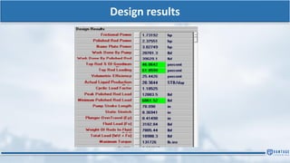
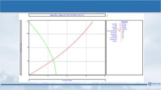
SUCKER ROD PUMP/BEAM PUMP
Sucker Rod Pump
ADVANTAGES
• It is a well-known lifting method to field personnel everywhere and is simple to operate and analyze
• Proper installation design is relatively simple and can also be made in the field
• Under average conditions, it can be used until the end of a well’s life.
• Pumping capacities within limits, can easily be changed to accommodate changes in well inflow
performance. Intermittent operation is also feasible using pump-off control devices
• System components and replacement parts are readily available and interchangeable worldwide
DISADVATAGES
• Pumping depth is limited, mainly by the mechanical strength of the sucker rod material
• Free gas present at pump intake drastically reduces liquid production
• In deviated wells, friction of metal parts can lead to mechanical failures
• Surface pumping units requires a large space and it is also heavy and obtrusive.
SRP Components
The individual components of a sucker-rod pumping system can be
divided in two major groups:
• surface and
• downhole equipment.
The surface equipment includes:
• The prime mover that provides the driving power to the system and can be
an electric motor or a gas engine.
• The gear reducer or gearbox reduces the high rotational speed of the
prime mover to the required pumping speed and, at the same time,
increases the torque available at its slow speed shaft.
• The pumping unit, a mechanical linkage that transforms the rotary motion
of the gear reducer into the reciprocating motion required to operate the
downhole pump. Its main element is the walking beam, which works on
the principle of a mechanical lever.
• The polished rod connects the walking beam to the sucker-rod string and
ensures a sealing surface at the wellhead to keep well fluids within the
well.
• The wellhead assembly contains a stuffing box that seals on the polished
rod and a pumping tee to lead well fluids into the flowline. The casing-
tubing annulus is usually connected, through a check valve, to the flowline.
SRP Components
The downhole equipment includes:
• The rod string composed of sucker rods, run inside the
tubing string of the well.
• The rod string provides the mechanical link between the
surface drive and the subsurface pump.
The pump plunger, the moving part of a usual sucker-rod pump is
directly connected to the rod string. It houses a ball valve, called
traveling valve, which, during the upward movement of the
plunger, lifts the liquid contained in the tubing.
The pump barrel or working barrel is the stationary part (cylinder)
of the subsurface pump.
Another ball valve, the standing valve, is fixed to the working
barrel. This acts as a suction valve for the pump, through which
well fluids enter the pump barrel during upstroke.
Types of Sucker Rod Pumps
There are several pumping units for sucker rod pumping. These units are
divided depending upon their geometric configurations as:
Class I lever system – Conventional type
Class III lever system – Air balanced type
Class III lever system- Mark II of Lufkin
Conventional Type
In this type of unit, the walking beam is supported at and moves about its
center.
The walking beam here acts as a double arm lever on the two sides of the
pivot i.e. the Sampson post where pivot is near to the middle of the walking
beam.
The rear end of the walking beam is the driving end and the front end of the
walking beam is the driven end. This is also called a “pull-up” leverage system.
The counterweights are positioned either at the rear end of the walking beam
or at the crank arm depending on the load at the well to reduce the torque
and horsepower of the prime mover of the pumping unit.
For fewer loads, counterweights are placed on the beam and for the moderate
to heavier loads, counterweights are placed on the cranks.
Types of Sucker rod Pump
Air balanced type
• This unit acts as a single arm lever (Class III) system where the horsehead
and the Pitman arm are on the same side of the beam and the pivot at
the extreme end of the beam.
• This is also called “push-up” leverage system.
• The counterbalance is ensured by the pressure force of compressed air
contained in a cylinder which acts on a piston connected to the bottom
of the walking beam.
Mark II Type
• The pivot is at one extreme end of the walking beam. The main
advantage of this unit is to decrease the torque and power requirements
of the pumping units.
• It implies that the pumping unit of this type having less torque and
power requirement can work for operating the pump at deeper depth in
contrast to the heavier capacity conventional pumping unit required to
operate at that depth.
• In Mark II Unit the counterweights are placed on the counter balance
arm that is on other side of the crank arm. This feature also ensures a
more uniform net torque variation throughout the complete pumping
cycle
API Subsurface Pump Designation
Example:
A 1 1⁄4 in. (31.8 mm) bore rod type
pump with a 10 ft. (3.048 m) heavy wall
barrel and 2 ft. (0.610 m) upper
extension, 2ft (0.610 m) lower
extension, a 4 ft. (1.219 m) plunger, and
a bottom cup type seating assembly for
operation in 2 3⁄8 in. (60.3 mm) tubing,
would be designated as follows:
20-125 RHBC 10–4–2–2
API subsurface pumps are categorized according to the API pump designation. The basic
types of pumps and letter designation are shown in the following Table:
Type of Pump:
Rod pump (R) – A rod pump, also called insert pump, is mounted inside the tubing string.
Advantage: Lower service costs compared to tubing pumps, as the pump can be removed by
pulling only the rod string.
Limitation: Lower production capacity compared to a tubing pump due to the smaller diameter of
the plunger.
Tubing pump (T) – The barrel of a tubing pump is part of the tubing string.
Advantages
•Largest displacement than any rod pump designated for the same tubing size.
•Deployable in wells of all depths due to the rigid design. This robustness is the result of the
pump barrel forming a unit with the tubing string.
•Good performance with fluids of higher viscosity as the large size of the plunger leads to a low
resistance to flow.
Limitations
•Higher service costs, as the barrel can only be serviced by removing the tubing string.
•Not suited for gassy production fluids because of a large upswept space at the bottom of the
stroke resulting in a low compression ratio.
•The larger bore of the tubing pump also means a larger bore acting on the rod string and
pumping unit
Type of Barrel
Heavy wall – 10-12 mm (0.393 – 0.472 in) wall
tubing. Externally threaded, allowing the plunger to stroke out at
both sides of the pump. The stroke-through construction
prevents scale formation inside the barrel. Stronger and more
rigid, for greater setting depth.
•With metal plunger (H)
•With soft-packed plunger (P)
Thin wall – 5-7 mm (0.197 – 0.276 in) wall
tubing. Internally threaded. Largest bore relative to a given
tubing size. For moderate depths.
•With metal plunger (W)
•With soft-packed plunger (S)
Heavy wall with thin-wall thread configuration (X) – 10-12
mm heavy-wall tubing, internally threaded. As the x-type barrel
does not require upper and lower extensions like a heavy-wall
barrel that could fail under pressure, even greater seating depths
are possible.
Location of Seating Assembly:
Top, with stationary barrel (A): Stationary barrel with moving plunger. The anchor (hold-down) is
located above the standing valve of the barrel.
Advantages
•Ideally suited for sandy wells as sand is washed away from the seating nipple when fluid is pumped.
•Reduces corrosive attack on the exterior of the barrel.
•Good performance in gassy wells or foamy wells with low fluid levels, when the standing valve is
submerged in the fluid. It is recommended to run the pump in combination with a gas anchor.
Limitation
•Not well suited for deep wells, especially if equipped with a thin-wall barrel. This is due to the relatively
high differential pressure and the tensile load acting on the barrel during pumping.
Bottom, with stationary barrel (B): Stationary barrel with moving plunger. The anchor (hold-down) is
located below the standing valve of the barrel.
Advantages
•Recommended for deep wells as the differential pressure acting on the barrel when pumping fluid is low.
•Appropriate for low static fluid levels as the pump can be seated close to the bottom hole and the
relatively large standing valve improves fluid intake.
•Good performance in gassy wells if equipped with a gas anchor. The small height difference between the
pump inlet to the standing valve reduces foaming of the fluid.
Limitations
•Not suited in wells with scale formation, as sand and other particles can settle between the tubing wall
and barrel.
•Not advisable for intermittent pumping operations, as the barrel can get stuck when solids settle on the
plunger
Design Data for API Sucker Rod Pumping Units
The Pumping Cycle
• The subsurface pumps used in sucker rod pumping work on the
principle of positive displacement and are of the cylinder and the
piston type.
• Their basic parts are the working barrel, the plunger and the two ball
valves. The barrel acts as the cylinder and the plunger as the piston.
• The valve affixed to the working barrel acts as a suction valve and is
called the standing valve.
• The other valve, contained in the plunger, acts as a discharge valve
and is called the traveling valve.
• These valves operate like check valves and their opening and closing
during the alternating movement of the plunger provides a means to
displace well fluids to the surface.
• The barrel is connected to the lower end of the tubing string, while
the plunger is directly moved by the rod string.
• The positions of the barrel and the plunger, as well as the operation
of the standing valve and the traveling valve are shown at the two
extreme positions of the up and down stroke
Pumping Cycle - Upstroke
• At the start of the upstroke, after the plunger has reached its lowermost
position, the traveling valve closes due to the high hydrostatic pressure in
the tubing above it.
• Liquid contained in the tubing above the traveling valve is lifted to the
surface during the upward movement of the plunger.
• At the same time, the pressure drops in the space between the standing
and traveling valves, causing the standing valve to open.
• Wellbore pressure drives the liquid from the formation through the
standing valve into the barrel below the plunger.
• Lifting of the liquid column and filling of the barrel with formation fluid
continues until the end of the upstroke.
• During the whole upstroke, full weight of the liquid column in the tubing
string is carried by the plunger and the rod string connected to it.
• The high pulling force causes the rod string to stretch, due to its
elasticity.
Pumping Cycle - Downstroke
After the plunger has reached the top of its stroke, the rod string starts to
move downwards. The downstroke begins, the traveling valve
immediately opens, and the standing valve closes.
This operation of the valves is due to its incompressibility of the liquid
contained in the barrel. When the traveling valve opens, liquid weight is
transferred from the plunger to the standing valve, causing the tubing
string to stretch.
During downstroke, the plunger makes its descent with the open traveling
valve inside the barrel filled with formation fluid. At the end of the
downstroke, the direction of the rod string’s movement is reversed and
another pumping cycle begins.
Liquid weight is again transferred to the plunger, making the rods stretch
and the tubing to return to its unstretched state.
Downhole Diagnostics
Dynamometer
• A Dynamometer quantifies the loading on the rod string and how
the pump is operating from stroke to stroke.
• A dynamometer is attached to the top of the rod string and
measures the changing load on the Polished Rod each stroke that
results from the rods (pump plunger) carrying the fluid load on the
upstroke and releasing the fluid load on the down-stroke. A plot of
of the surface acquired Load vs. Position data is known as
the Surface Card (Ex: the "duck" looking card above).
• The Wave Equation (which accounts for the elastic nature of the
rod string in its dynamic motion) is applied to the Surface Card in
order to mathematically filter the surface data to calculate what is
happening at the downhole pump.
• A plot of the converted data is known as the downhole Pump
Card and represents the load on the pump's plunger as the plunger
moves up and down through each pump stroke (shown in the
rectangular "panhandle" cards above).
• By observing the shape of the Pump Card during a single stroke—
and also comparing successive pump strokes to see how the shape
changes during the run cycle—the downhole operating conditions,
producing efficiency, and pump performance can be evaluated.
Fluid Pound
Occurs when the downhole pump rate exceeds the production rate
of the formation. It can also be due to the accumulation of low-
pressure gas between the valves.
On the downstroke of the pump, the gas is compressed, but the
pressure inside the barrel does not open the traveling valve until
the traveling valve strikes the liquid.
Finally when the traveling valve opens, the weight on the rod
string can suddenly drop thousands of pounds in a fraction of a
second.
This condition should be avoided because it causes extreme
stresses, which can result in premature equipment failure.
Slowing down the pumping unit, shortening the stroke length or
installing a smaller bottom hole pump can correct this problem.
Gas Interference
Occurs when gas enters the subsurface sucker-rod pump.
After the downstroke begins, the compressed gas reaches the
pressure needed to open the traveling valve before the
traveling valve reaches liquid.
The traveling valve opens slowly, without the drastic load
change experienced in fluid pound.
It does not cause premature equipment failure, but can indicate
poor pump efficiency.
A bottomhole separator or a gas anchor can correct gas
interference.
Unanchored Tubing
The top two cards show a pump that is full of
liquid, but the one the right has the tubing un-
anchored.
This allows the tubing to travel upward some
on the upstroke and the pick-up of the load
takes place over a distance of upstroke,
resulting in a slanting of the sides of the card
with the un-anchored tubing.
Worn out Tubing
Leaky Traveling Valve and Standing Valve
Leaking Traveling Valve Leaking Standing Valve
Operating Parameters
The minimum amount of information which must either be known or assumed is follows:
• Fluid Level, ft.
• Pump depth, ft.
• Pumping speed, SPM
• Length of Surface stroke, in.
• Pump plunger diameter, in.
• Specific gravity of fluid
• The nominal tubing diameter and whether it is anchored or unanchored
• Sucker rod size and design
With these factors, the designer should be able to calculate, with some degree of reliability, the following:
• Plunger stroke length, 𝑆𝑝,
• Plunger displacement, PD, (B/D)
• Peak polished rod load, PPRL, lb.
• Minimum polished rod load, MPRL lb.
• Peak (Crank) torque, PT, in-lb.
• Polished rod horsepower, PRHP
• Counter weight required, CBE, lb.
Sucker Rod Pump Operating
Parameters & Calculations
Minimum and maximum value of acceleration
• When wt = 0, maximum acceleration takes place:
• Similarly, the minimum value of acceleration is
• For air-balanced units, because of the arrangements of the
levers, the acceleration occurs at the bottom of the stroke,
and the acceleration occurs at the top. With the lever system
of an air-balanced unit, the polished rod is at the top of its
stroke when the crank arm is vertically upward.
• The PRL is the sum of weight of
fluid being lifted, weight of plunger,
weight of sucker rods string,
dynamic load due to acceleration,
friction force, and the up-thrust
from below on plunger.
• We assume the TV is closed at the
instant at which the acceleration
term reaches its maximum.
• For Air- balanced unit, M is replaced by 1-c/h.
• Hence,
Maximum Polished Rod Load (PRLmax)
• Substituting Sucker Rod Cross-sectional area value
• The above equation is often further reduced by taking the fluid in the second term (the subtractive
term) as an 50 API with Sf = 0.78. Thus, Eq. becomes
Minimum Polished rod load (PRLmin)
• The minimum PRL occurs while the
TV is open so that the fluid column
weight is carried by the tubing and
not the rods.
• The minimum load is at or near the
top of the stroke.
• Neglecting the weight of the plunger
and friction term, the minimum PRL
is
To reduce the power requirements for the prime mover, a counterbalance
load is used on the walking beam (small units) or the rotary crank. The ideal
counterbalance load C is the average PRL. Therefore,
• The peak torque exerted is usually calculated on the most severe possible assumption,
which is that the peak load (polished rod less counterbalance) occurs when the
effective crank length is also a maximum (when the crank arm is horizontal)
• Stroke per minute (SPM) limit
Optimization of Sucker Rod Pump System
To optimize the existing system, the crank radius, the speed of the pump, and the position of the counterbalance are alterable values. The
following steps form an optimizing procedure: (Miska, Tulsa, Khodabandeh, & Rajtar, 1994)
1. Change the speed of the pumping unit, keeping a preselected crank radius. Do not allow the PPRL and the peak net torque to exceed the
rating of the pumping unit. The upper limit for the pumping speed (strokes/min) will then be determined.
2. Calculate the production rate, PPRL, peak torque, polished-rod horsepower, and output energy of the prime mover at each pumping
speed not exceeding the upper pumping speed limit.
3. Change the crank radius and repeat Steps 1 and 2. As usual, the number of crank radii is limited. This task can he accomplished in a
relatively short time.
4. Select the optimum pumping speed for each radius (stroke length) that yields the desired oil production rate. Then, construct the net
torque diagrams for the selected speeds for further analysis.
5. Typically, a few combinations of different pumping speeds and stroke lengths will result in a desired production rate. Discard the
combinations that do not meet the specifications and rating of the system. The optimal choice is determined by calculating the efficiency
and operational costs associated with combinations. The parameters corresponding to the minimum cost are optimal.
6. Change the direction of crank rotation, if permissible, and repeat Steps 1 through 5. This is not required if the optimum direction of
rotation is known from the past experience.
7. Check the final results against the limitations of the surface and downhole equipment. The optimal production practices, as determined
in the steps above, may require some modifications or adjustment to the equipment. If the cost associated with the modifications is
lower than the benefits of optimization the practical implementation of the results is justified and will result in production cost decrease.
Design results
Rod Sensitivity
Pumping Speed Sensitivity

Sucker Rod Pump design artificial lifting

  • 1.
  • 2.
    Sucker Rod Pump ADVANTAGES •It is a well-known lifting method to field personnel everywhere and is simple to operate and analyze • Proper installation design is relatively simple and can also be made in the field • Under average conditions, it can be used until the end of a well’s life. • Pumping capacities within limits, can easily be changed to accommodate changes in well inflow performance. Intermittent operation is also feasible using pump-off control devices • System components and replacement parts are readily available and interchangeable worldwide DISADVATAGES • Pumping depth is limited, mainly by the mechanical strength of the sucker rod material • Free gas present at pump intake drastically reduces liquid production • In deviated wells, friction of metal parts can lead to mechanical failures • Surface pumping units requires a large space and it is also heavy and obtrusive.
  • 3.
    SRP Components The individualcomponents of a sucker-rod pumping system can be divided in two major groups: • surface and • downhole equipment. The surface equipment includes: • The prime mover that provides the driving power to the system and can be an electric motor or a gas engine. • The gear reducer or gearbox reduces the high rotational speed of the prime mover to the required pumping speed and, at the same time, increases the torque available at its slow speed shaft. • The pumping unit, a mechanical linkage that transforms the rotary motion of the gear reducer into the reciprocating motion required to operate the downhole pump. Its main element is the walking beam, which works on the principle of a mechanical lever. • The polished rod connects the walking beam to the sucker-rod string and ensures a sealing surface at the wellhead to keep well fluids within the well. • The wellhead assembly contains a stuffing box that seals on the polished rod and a pumping tee to lead well fluids into the flowline. The casing- tubing annulus is usually connected, through a check valve, to the flowline.
  • 4.
    SRP Components The downholeequipment includes: • The rod string composed of sucker rods, run inside the tubing string of the well. • The rod string provides the mechanical link between the surface drive and the subsurface pump. The pump plunger, the moving part of a usual sucker-rod pump is directly connected to the rod string. It houses a ball valve, called traveling valve, which, during the upward movement of the plunger, lifts the liquid contained in the tubing. The pump barrel or working barrel is the stationary part (cylinder) of the subsurface pump. Another ball valve, the standing valve, is fixed to the working barrel. This acts as a suction valve for the pump, through which well fluids enter the pump barrel during upstroke.
  • 5.
    Types of SuckerRod Pumps There are several pumping units for sucker rod pumping. These units are divided depending upon their geometric configurations as: Class I lever system – Conventional type Class III lever system – Air balanced type Class III lever system- Mark II of Lufkin Conventional Type In this type of unit, the walking beam is supported at and moves about its center. The walking beam here acts as a double arm lever on the two sides of the pivot i.e. the Sampson post where pivot is near to the middle of the walking beam. The rear end of the walking beam is the driving end and the front end of the walking beam is the driven end. This is also called a “pull-up” leverage system. The counterweights are positioned either at the rear end of the walking beam or at the crank arm depending on the load at the well to reduce the torque and horsepower of the prime mover of the pumping unit. For fewer loads, counterweights are placed on the beam and for the moderate to heavier loads, counterweights are placed on the cranks.
  • 6.
    Types of Suckerrod Pump Air balanced type • This unit acts as a single arm lever (Class III) system where the horsehead and the Pitman arm are on the same side of the beam and the pivot at the extreme end of the beam. • This is also called “push-up” leverage system. • The counterbalance is ensured by the pressure force of compressed air contained in a cylinder which acts on a piston connected to the bottom of the walking beam. Mark II Type • The pivot is at one extreme end of the walking beam. The main advantage of this unit is to decrease the torque and power requirements of the pumping units. • It implies that the pumping unit of this type having less torque and power requirement can work for operating the pump at deeper depth in contrast to the heavier capacity conventional pumping unit required to operate at that depth. • In Mark II Unit the counterweights are placed on the counter balance arm that is on other side of the crank arm. This feature also ensures a more uniform net torque variation throughout the complete pumping cycle
  • 8.
    API Subsurface PumpDesignation Example: A 1 1⁄4 in. (31.8 mm) bore rod type pump with a 10 ft. (3.048 m) heavy wall barrel and 2 ft. (0.610 m) upper extension, 2ft (0.610 m) lower extension, a 4 ft. (1.219 m) plunger, and a bottom cup type seating assembly for operation in 2 3⁄8 in. (60.3 mm) tubing, would be designated as follows: 20-125 RHBC 10–4–2–2
  • 9.
    API subsurface pumpsare categorized according to the API pump designation. The basic types of pumps and letter designation are shown in the following Table:
  • 10.
    Type of Pump: Rodpump (R) – A rod pump, also called insert pump, is mounted inside the tubing string. Advantage: Lower service costs compared to tubing pumps, as the pump can be removed by pulling only the rod string. Limitation: Lower production capacity compared to a tubing pump due to the smaller diameter of the plunger. Tubing pump (T) – The barrel of a tubing pump is part of the tubing string. Advantages •Largest displacement than any rod pump designated for the same tubing size. •Deployable in wells of all depths due to the rigid design. This robustness is the result of the pump barrel forming a unit with the tubing string. •Good performance with fluids of higher viscosity as the large size of the plunger leads to a low resistance to flow. Limitations •Higher service costs, as the barrel can only be serviced by removing the tubing string. •Not suited for gassy production fluids because of a large upswept space at the bottom of the stroke resulting in a low compression ratio. •The larger bore of the tubing pump also means a larger bore acting on the rod string and pumping unit
  • 11.
    Type of Barrel Heavywall – 10-12 mm (0.393 – 0.472 in) wall tubing. Externally threaded, allowing the plunger to stroke out at both sides of the pump. The stroke-through construction prevents scale formation inside the barrel. Stronger and more rigid, for greater setting depth. •With metal plunger (H) •With soft-packed plunger (P) Thin wall – 5-7 mm (0.197 – 0.276 in) wall tubing. Internally threaded. Largest bore relative to a given tubing size. For moderate depths. •With metal plunger (W) •With soft-packed plunger (S) Heavy wall with thin-wall thread configuration (X) – 10-12 mm heavy-wall tubing, internally threaded. As the x-type barrel does not require upper and lower extensions like a heavy-wall barrel that could fail under pressure, even greater seating depths are possible.
  • 12.
    Location of SeatingAssembly: Top, with stationary barrel (A): Stationary barrel with moving plunger. The anchor (hold-down) is located above the standing valve of the barrel. Advantages •Ideally suited for sandy wells as sand is washed away from the seating nipple when fluid is pumped. •Reduces corrosive attack on the exterior of the barrel. •Good performance in gassy wells or foamy wells with low fluid levels, when the standing valve is submerged in the fluid. It is recommended to run the pump in combination with a gas anchor. Limitation •Not well suited for deep wells, especially if equipped with a thin-wall barrel. This is due to the relatively high differential pressure and the tensile load acting on the barrel during pumping. Bottom, with stationary barrel (B): Stationary barrel with moving plunger. The anchor (hold-down) is located below the standing valve of the barrel. Advantages •Recommended for deep wells as the differential pressure acting on the barrel when pumping fluid is low. •Appropriate for low static fluid levels as the pump can be seated close to the bottom hole and the relatively large standing valve improves fluid intake. •Good performance in gassy wells if equipped with a gas anchor. The small height difference between the pump inlet to the standing valve reduces foaming of the fluid. Limitations •Not suited in wells with scale formation, as sand and other particles can settle between the tubing wall and barrel. •Not advisable for intermittent pumping operations, as the barrel can get stuck when solids settle on the plunger
  • 13.
    Design Data forAPI Sucker Rod Pumping Units
  • 14.
    The Pumping Cycle •The subsurface pumps used in sucker rod pumping work on the principle of positive displacement and are of the cylinder and the piston type. • Their basic parts are the working barrel, the plunger and the two ball valves. The barrel acts as the cylinder and the plunger as the piston. • The valve affixed to the working barrel acts as a suction valve and is called the standing valve. • The other valve, contained in the plunger, acts as a discharge valve and is called the traveling valve. • These valves operate like check valves and their opening and closing during the alternating movement of the plunger provides a means to displace well fluids to the surface. • The barrel is connected to the lower end of the tubing string, while the plunger is directly moved by the rod string. • The positions of the barrel and the plunger, as well as the operation of the standing valve and the traveling valve are shown at the two extreme positions of the up and down stroke
  • 15.
    Pumping Cycle -Upstroke • At the start of the upstroke, after the plunger has reached its lowermost position, the traveling valve closes due to the high hydrostatic pressure in the tubing above it. • Liquid contained in the tubing above the traveling valve is lifted to the surface during the upward movement of the plunger. • At the same time, the pressure drops in the space between the standing and traveling valves, causing the standing valve to open. • Wellbore pressure drives the liquid from the formation through the standing valve into the barrel below the plunger. • Lifting of the liquid column and filling of the barrel with formation fluid continues until the end of the upstroke. • During the whole upstroke, full weight of the liquid column in the tubing string is carried by the plunger and the rod string connected to it. • The high pulling force causes the rod string to stretch, due to its elasticity.
  • 16.
    Pumping Cycle -Downstroke After the plunger has reached the top of its stroke, the rod string starts to move downwards. The downstroke begins, the traveling valve immediately opens, and the standing valve closes. This operation of the valves is due to its incompressibility of the liquid contained in the barrel. When the traveling valve opens, liquid weight is transferred from the plunger to the standing valve, causing the tubing string to stretch. During downstroke, the plunger makes its descent with the open traveling valve inside the barrel filled with formation fluid. At the end of the downstroke, the direction of the rod string’s movement is reversed and another pumping cycle begins. Liquid weight is again transferred to the plunger, making the rods stretch and the tubing to return to its unstretched state.
  • 17.
  • 18.
    Dynamometer • A Dynamometerquantifies the loading on the rod string and how the pump is operating from stroke to stroke. • A dynamometer is attached to the top of the rod string and measures the changing load on the Polished Rod each stroke that results from the rods (pump plunger) carrying the fluid load on the upstroke and releasing the fluid load on the down-stroke. A plot of of the surface acquired Load vs. Position data is known as the Surface Card (Ex: the "duck" looking card above). • The Wave Equation (which accounts for the elastic nature of the rod string in its dynamic motion) is applied to the Surface Card in order to mathematically filter the surface data to calculate what is happening at the downhole pump. • A plot of the converted data is known as the downhole Pump Card and represents the load on the pump's plunger as the plunger moves up and down through each pump stroke (shown in the rectangular "panhandle" cards above). • By observing the shape of the Pump Card during a single stroke— and also comparing successive pump strokes to see how the shape changes during the run cycle—the downhole operating conditions, producing efficiency, and pump performance can be evaluated.
  • 19.
    Fluid Pound Occurs whenthe downhole pump rate exceeds the production rate of the formation. It can also be due to the accumulation of low- pressure gas between the valves. On the downstroke of the pump, the gas is compressed, but the pressure inside the barrel does not open the traveling valve until the traveling valve strikes the liquid. Finally when the traveling valve opens, the weight on the rod string can suddenly drop thousands of pounds in a fraction of a second. This condition should be avoided because it causes extreme stresses, which can result in premature equipment failure. Slowing down the pumping unit, shortening the stroke length or installing a smaller bottom hole pump can correct this problem.
  • 20.
    Gas Interference Occurs whengas enters the subsurface sucker-rod pump. After the downstroke begins, the compressed gas reaches the pressure needed to open the traveling valve before the traveling valve reaches liquid. The traveling valve opens slowly, without the drastic load change experienced in fluid pound. It does not cause premature equipment failure, but can indicate poor pump efficiency. A bottomhole separator or a gas anchor can correct gas interference.
  • 21.
    Unanchored Tubing The toptwo cards show a pump that is full of liquid, but the one the right has the tubing un- anchored. This allows the tubing to travel upward some on the upstroke and the pick-up of the load takes place over a distance of upstroke, resulting in a slanting of the sides of the card with the un-anchored tubing. Worn out Tubing Leaky Traveling Valve and Standing Valve
  • 22.
    Leaking Traveling ValveLeaking Standing Valve
  • 23.
    Operating Parameters The minimumamount of information which must either be known or assumed is follows: • Fluid Level, ft. • Pump depth, ft. • Pumping speed, SPM • Length of Surface stroke, in. • Pump plunger diameter, in. • Specific gravity of fluid • The nominal tubing diameter and whether it is anchored or unanchored • Sucker rod size and design With these factors, the designer should be able to calculate, with some degree of reliability, the following: • Plunger stroke length, 𝑆𝑝, • Plunger displacement, PD, (B/D) • Peak polished rod load, PPRL, lb. • Minimum polished rod load, MPRL lb. • Peak (Crank) torque, PT, in-lb. • Polished rod horsepower, PRHP • Counter weight required, CBE, lb.
  • 24.
    Sucker Rod PumpOperating Parameters & Calculations
  • 25.
    Minimum and maximumvalue of acceleration • When wt = 0, maximum acceleration takes place: • Similarly, the minimum value of acceleration is • For air-balanced units, because of the arrangements of the levers, the acceleration occurs at the bottom of the stroke, and the acceleration occurs at the top. With the lever system of an air-balanced unit, the polished rod is at the top of its stroke when the crank arm is vertically upward.
  • 26.
    • The PRLis the sum of weight of fluid being lifted, weight of plunger, weight of sucker rods string, dynamic load due to acceleration, friction force, and the up-thrust from below on plunger. • We assume the TV is closed at the instant at which the acceleration term reaches its maximum. • For Air- balanced unit, M is replaced by 1-c/h. • Hence,
  • 27.
    Maximum Polished RodLoad (PRLmax) • Substituting Sucker Rod Cross-sectional area value • The above equation is often further reduced by taking the fluid in the second term (the subtractive term) as an 50 API with Sf = 0.78. Thus, Eq. becomes
  • 28.
    Minimum Polished rodload (PRLmin) • The minimum PRL occurs while the TV is open so that the fluid column weight is carried by the tubing and not the rods. • The minimum load is at or near the top of the stroke. • Neglecting the weight of the plunger and friction term, the minimum PRL is
  • 29.
    To reduce thepower requirements for the prime mover, a counterbalance load is used on the walking beam (small units) or the rotary crank. The ideal counterbalance load C is the average PRL. Therefore,
  • 30.
    • The peaktorque exerted is usually calculated on the most severe possible assumption, which is that the peak load (polished rod less counterbalance) occurs when the effective crank length is also a maximum (when the crank arm is horizontal) • Stroke per minute (SPM) limit
  • 31.
    Optimization of SuckerRod Pump System To optimize the existing system, the crank radius, the speed of the pump, and the position of the counterbalance are alterable values. The following steps form an optimizing procedure: (Miska, Tulsa, Khodabandeh, & Rajtar, 1994) 1. Change the speed of the pumping unit, keeping a preselected crank radius. Do not allow the PPRL and the peak net torque to exceed the rating of the pumping unit. The upper limit for the pumping speed (strokes/min) will then be determined. 2. Calculate the production rate, PPRL, peak torque, polished-rod horsepower, and output energy of the prime mover at each pumping speed not exceeding the upper pumping speed limit. 3. Change the crank radius and repeat Steps 1 and 2. As usual, the number of crank radii is limited. This task can he accomplished in a relatively short time. 4. Select the optimum pumping speed for each radius (stroke length) that yields the desired oil production rate. Then, construct the net torque diagrams for the selected speeds for further analysis. 5. Typically, a few combinations of different pumping speeds and stroke lengths will result in a desired production rate. Discard the combinations that do not meet the specifications and rating of the system. The optimal choice is determined by calculating the efficiency and operational costs associated with combinations. The parameters corresponding to the minimum cost are optimal. 6. Change the direction of crank rotation, if permissible, and repeat Steps 1 through 5. This is not required if the optimum direction of rotation is known from the past experience. 7. Check the final results against the limitations of the surface and downhole equipment. The optimal production practices, as determined in the steps above, may require some modifications or adjustment to the equipment. If the cost associated with the modifications is lower than the benefits of optimization the practical implementation of the results is justified and will result in production cost decrease.
  • 32.
  • 34.
  • 35.