Download as PDF, PPTX


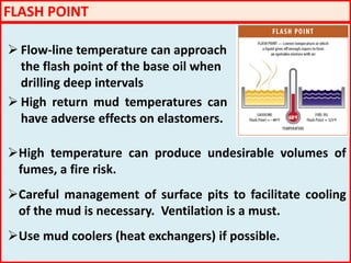
![CONTAMINATION
HTHP wells often face contamination problems
Acid gas (H2S & CO2). These gases create their own problems.
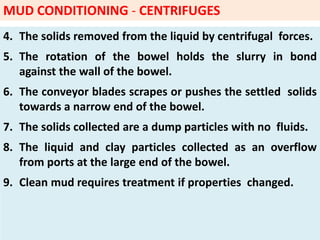
Higher mud weights are used in HPHT wells [1.90 - 2.30] - the
weighing material may be contaminated - for instance, silt is
always present in barite.
Longer trip times (no circulation for extended times). The
drilling fluid is exposed to high BHST for long periods of time.
Drilled solids are also a major contaminant affecting the
rheology of the drilling fluid in conditions of high
temperature.](https://image.slidesharecdn.com/drillingfluidsforthehphtenvironment-170727170713/85/DRILLING-FLUIDS-FOR-THE-HPHT-ENVIRONMENT-50-320.jpg)
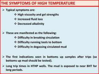
![EXTENDING TEMPERATURE LIMITS
The temperature limitations of the chemicals used in the formulation of
the HPHT drilling fluid can be extended by a few pertinent steps.
pH 9.5 - 10 to be maintained. This helps in extending the temperature
limits.
Oxygen scavenging can increase the temperature limit by 25 deg F
Formulating in brine - this can extend the temperature limit by 50 deg F
and brine acts as a powerful antioxidant and has less solids. Therefore,
we have lesser flocculation problems.
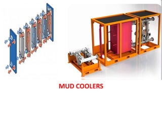
And last but definitely not the least - use of a mud cololer. Mud coolers
bring down the temperatures to which the drilling fluid and its
components are subjected to. Depending on the mud cooler, the
temperature of the drilling fluid can be brought down by nearly 15 to
30 deg C [58 to 86 deg F]](https://image.slidesharecdn.com/drillingfluidsforthehphtenvironment-170727170713/85/DRILLING-FLUIDS-FOR-THE-HPHT-ENVIRONMENT-55-320.jpg)


The document presents a comprehensive overview of drilling fluids for high-pressure high-temperature (HPHT) wells, emphasizing the need for effective mud evaluation, treatment, and cooling to maximize efficiency and minimize risks. It details the criteria for selecting mud types, the importance of managing equivalent circulating density (ECD), and the challenges posed by environmental factors and mechanical properties. Key topics include the behavior of invert emulsion fluids, cesium formate brines, and the design of hydraulic systems to prevent well control incidents.


