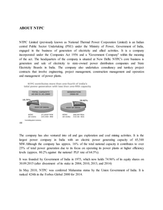
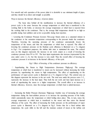
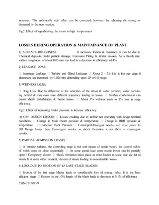
TRAINING AT NTPC
I was appointed to do 4 week training at this esteemed organization from 13th June to 9th July,
2016. I was assigned to visit various division of the plant, which were:
 BMD (BOILER MAINTANANCE DEPARTMENT)
 TMD (TURBINE MAITAINANCE DEPARTMENT)
These 4 weeks training was a very educational adventure for me. It was really amazing to see the
plant by yourself and learn how electricity, which is one of our daily requirements of life, is
produced. This report has been made by my experience at NTPC. The material in this report
has been gathered from my textbook, senior student reports and trainers manuals and
power journals provided by training department. The specification and principles are as learned
by me from the employees of each division of NTPC.
ABOUT NTPC
NTPC Limited (previously known as National Thermal Power Corporation Limited) is an Indian
central Public Sector Undertaking (PSU) under the Ministry of Power, Government of India,
engaged in the business of generation of electricity and allied activities. It is a company
incorporated under the Companies Act 1956 and a "Government Company" within the meaning
of the act. The headquarters of the company is situated at New Delhi. NTPC's core business is
generation and sale of electricity to state-owned power distribution companies and State
Electricity Boards in India. The company also undertakes consultancy and turnkey project
contracts that involve engineering, project management, construction management and operation
and management of power plants.
The company has also ventured into oil and gas exploration and coal mining activities. It is the
largest power company in India with an electric power generating capacity of 45,548
MW.Although the company has approx. 16% of the total national capacity it contributes to over
25% of total power generation due to its focus on operating its power plants at higher efficiency
levels (approx. 80.2% against the national PLF rate of 64.5%).
It was founded by Government of India in 1975, which now holds 74.96% of its equity shares on
30.09.2015 (after divestment of its stake in 2004, 2010, 2013, and 2014)
In May 2010, NTPC was conferred Maharatna status by the Union Government of India. It is
ranked 424th in the Forbes Global 2000 for 2014.
History
 1975 to 1994
The company was founded in November 1975 as "National Thermal Power Corporation Private
Limited". It started work on its first thermal power project in 1976 at Shaktinagar (named
National Thermal Power Corporation Private Limited Singrauli) in Uttar Pradesh. In the same
year, its name was changed to "National Thermal Power Corporation Limited". In 1983, NTPC
began commercial operations (of selling power) and earned profits of INR 4.5 crores in FY
1982-83. By the end of 1985, it had achieved power generation capacity of 2000 MW.
In 1986, it completed synchronisation of its first 500 MW unit at Singrauli. In 1988, it
commissioned two 500 MW units, one each in Rihand and Ramagundam. In 1989, it started a
consultancy division. In 1992, it acquired Feroze Gandhi Unchahar Thermal Power Station (with
2 units of 210MW capacity each) from Uttar Pradesh Rajya Vidyut Utpadan Nigam of Uttar
Pradesh. By the end of 1994, its installed capacity crossed 15,000 MW.
 1995 to 2004
In 1995, it took over the Talchar Thermal Power Station from Orissa State Electricity Board. In
the year 1997, Government of India conferred it with "Navratna" status. In the same year it
achieved a milestone of generation of 100 billion units of electricity in a year. In 1998, it
commissioned its first naptha-based plant at Kayamkulam with a capacity of 350 MW. In 1999,
its plant in Dadri, which had the highest plant load factor (PLF) in India of 96%, was certified
with ISO-14001. During 2000, it commenced construction of its first hydro-electric power
project, with 800 MW capacity, in Himachal Pradesh.
In 2002, it incorporated 3 subsidiary companies: "NTPC Electric Supply Company Limited" for
forward integration by entering into the business of distribution and trading of power; "NTPC
Vidyut Vyapar Nigam Limited" for meeting the expected rise in energy trading; "NTPC Hydro
Limited" to carry out the business of implementing and operating small and medium hydro-
power projects. In the same year its installed capacity crossed 20,000 MW.
Listing: NTPC got listed on BSE and NSE on 5 November 2004. Against the issue price of INR
62 per share, it closed the first day of listing with INR 75.55 per share. On the day of listing, it
become the third largest company in India in terms of market capitalisation.
 2005 to present
In October 2005, the company's name was changed from "National Thermal Power Corporation
Limited" to "NTPC Limited". The primary reason for this change was the company's foray into
hydro and nuclear based power generation along with backward integration by coal mining. In
2006, it entered into an agreement with Government of Sri Lanka to set up two units of 250 MW
each in Trincomalee in Sri Lanka.During 2008 and 2011, NTPC entered into Joint Ventures with
BHEL, Bharat Forge, NHPC, Coal India, SAIL, NMDC and NPCIL to expand its business of
power generation.By the end of 2010, its installed capacity crossed 31,000 MW.
The company in 2009 joined forces with other state enterprises Rashtriya Ispat Nigam, Steel
Authority of India, Coal India, National Minerals Development Corporation and National
Thermal Power Corporation to invest in coal mining operations through a joint venture vehicle
named International Coal Ventures Private Limited (ICVL). In July 2014 ICVL acquired a 65
percent stake in the Bengal coal mine in Mozambique from the Rio Tinto Group
Technological Initiatives
 Introduction of steam generators (boilers) of the size of 800 MW.
 Integrated Gasification Combined Cycle (IGCC) Technology.
 Launch of Energy Technology Centre -A new initiative for development of technologies
with focus on fundamental R&D.
 The company sets aside up to 0.5% of the profits for R&D.
 Roadmap developed for adopting µClean Development.
 Mechanism to help get / earn µCertified Emission Reduction.
Corporate Social Responsibility
 As a responsible corporate citizen NTPC has taken up number of CSR initiatives.
 NTPC Foundation formed to address Social issues at national level
 NTPC has framed Corporate Social Responsibility Guidelines committing up to0.5% of
net profit annually for Community Welfare.
 The welfare of project affected persons and the local population around NTPC projects
are taken care of through well drawn Rehabilitation and Resettlement policies.
 The company has also taken up distributed generation for remote rural areas
Partnering government in various initiatives
 Consultant role to modernize and improvise several plants across the country.
 Disseminate technologies to other players in the sector.
 Consultant role 'Partnership in Excellence' Programme for improvement of PLF of 15
Power Stations of SEBs.
 Rural Electrification work under Rajiv Gandhi Garmin Vidyutikaran.
About Feroze Gandhi Unchahar Thermal Power Station
 Approved capacity :1050 MW
 Installed Capacity :Stage I & II= 840 MW (2 x 210 + 2 x 210 MW) Stage III : 210
MW (1 x 210 MW)
 Location: Raibareli, Uttar Pradesh
 Coal Source : North Karanpura.
 Water Source: Sarda Sahayak Canal
 Beneficiary States :Uttar Pradesh, Haryana, Himachal Pradesh, J&K, Punjab,
Rajasthan, Chandigarh, Delhi, Uttaranchal
 Unit Sizes:
5x210 MW
Units Commissioned
Unit I : 210 MW November 1988
Unit II : 210 MW March 1989
Unit III : 210 MW January 1999
Unit IV : 210 MW October 1999
Unit V : 210 MW September 2006
 International Assistance: ADB
 Approved cost : Stage I & II : Rs.2337.09 Crores Stage III : Rs. 938.61 Crores.
Basic steps for electricity generation
 coal to steam
 steam to mechanical power
 mechanical power to electrical power
TYPICAL COAL POWER GENERATING PLANT
For units over about 200 MW capacity, redundancy of key components is provided by installing
duplicates of the forced and induced draft fans, air preheaters, and fly ash collectors. On some units of
about 60 MW, two boilers per unit may instead be provided. The list of coal power stations has the 200
largest power stations ranging in size from 2,000MW to 5,500MW.
BASIC POWER PLANT CYCLE: RANKINE CYCLE
The Rankine cycle is a cycle that converts heat into work. The heat is supplied externally to a
closed loop, which usually uses water. This cycle generates about 80% of all electric power used
throughout the world, including virtually all solar thermal, biomass, coal and nuclear power
plants. It is named after William John Macquorn Rankine, a Scottish polymath. The Rankine
cycle is the fundamental thermodynamic underpinning of the steam engine.
Overview of NTPC Unchahar Thermal Power Project:-
A thermal power station consists of all the equipments and a subsystem required to produce
electricity by using a steam generating boiler fired with fossil fuels or biofuels to drive an
electric generator. Some prefer to use the term ENERGY CENTER because such facilities
convert form of energy like nuclear energy, gravitational potential energy or heat energy (derived
from the combustion of fuel) into electrical energy.
The description of some of the components of the thermal power plant is as follows:
1 Cooling towers. -
Cooling towers are eveporative coolers used for cooling water. Cooling tower uses the concept
of evaporation of water to reject heat from processes such by cooling the circulaing water used
in oil refineries, chemical plants, power plants, etc. Smaller towers are normally factory built
while larger ones are constructed on site. The primary use of large, industrial cooling tower
system is to remove the heat by circulating the hot water used by the plants
The absorbed heat is rejected to the atmosphere by the evaporation of some of the cooling water
in mechanical forced – draft or induced draft towers or in natural draft hyperbolic shaped cooling
towers as seen at most nuclear power plants.
4 Nos Induced draft cooling towers with 10 fans each tower are installed at NTPC Unchahar for
the above said pupose.
2. Three phase transmission line& step- up transformer
Three phase electric power is a common method of electric power transmission. It is a type of
polyphase system mainly used for power motors and many other devices. In a three phase
system, three circuits reach their instantaneous peak values at different times. Taking one
conductor as reference, the other two conductors are delayed in time by one-third and two-third
of cycle of the electrical current. This delay between phases has the effect of giving constant
power over each cycle of the current and also makes it impossible to produce a rotating magnetic
field in an electric motor. At the power station, an electric generator converts mechanical power
into a set of electric currents one from each electromagnetic coil or winding of the generator. The
currents are sinusoidal functions of time, all at the same frequency but offset in time to give
different phases. In a three phase system, the phases are spaced equally giving a phase separation
of one-third of one cycle. Generators output at a voltage that ranges from
hundreds of volts to 30,000 volts at the power station. Transformers step-up this voltage for
suitable transmission after numerous further conversions in the transmission and distribution
network, the power is finally transformed to standard mains voltage i.e. the household voltage.
This voltage transmitted may be in three phase or in one phase only where we have the
corresponding step-down transformer at the receiving stage. The output of the transformer is
usually star connected with the standard mains voltage being the phase neutral voltage.
3. Electrical generator-
An electrical generator is a device that coverts mechanical energy to electrical energy, using
electromagnetic induction whereas electrical energy is converted to mechanical energy with the
help of electric motor. The source of mechanical energy may be a rotating shaft of steam turbine
engine. Turbines are made in variety of sizes ranging from small 1 hp(0.75 kW) used as
mechanical drives for pumps, compressors and other shaft driven equipment to 2,000,000
hp(1,500,000 kW) turbines used to generate electricity.
4. STEAM TURBINE
A steam turbine is a mechanical device that extracts thermal energy from pressurized steam, and
converts it into rotary motion. Its modern manifestation was invented by Sir Charles Parsons in
1884.
It has almost completely replaced the reciprocating piston steam engine primarily because of its
greater thermal efficiency and higher power-to-weight ratio. Because the turbine generates rotary
motion, it is particularly suited to be used to drive an electrical generator – about 80% of all
electricity generation in the world is by use of steam turbines. The steam turbine is a form of heat
engine that derives much of its improvement in thermodynamic efficiency through the use of
multiple stages in the expansion of the steam, which results in a closer approach to the ideal
reversible process.
4. Steam condenser -
The condenser condenses the steam from the exhaust of the turbine into liquid to allow it to be
pumped. If the condenser can be made cooler, the pressure of the exhaust steam is reduced and
efficiency of the cycle increases. The surface condenser is a shell and tube heat exchanger in
which cooling water is circulated through the tubes. The exhaust steam from the low pressure
turbine enters the shell where it is cooled and converted to condensate (water) by flowing over
the tubes as shown in the adjacent diagram. Such condensers use steam ejectors or rotary motor-
driven exhausters for continuous removal of air and gases from the steam side to maintain
vacuum.
5. Boiler Feed Pump-
A Boiler Feed Pump is a specific type of pump used to pump water into steam boiler. The water
may be freshly supplied or retuning condensation of steam produced by the boiler. These pumps
are normally high pressure units that use suction from a condensate return system and can be of
centrifugal pump type or positive displacement type. Construction and Operation feed water
pumps range from sizes upto many horsepower and the electric motor is usually separated from
the pump body by some form of mechanical coupling. Large industrial condensate pumps may
also serve as the feed water pump. In either case, to force water into the boiler, the pump must
generate sufficient pressure to overcome the steam pressure developed by the boiler. This is
usually accomplished through the use of centrifugal pump. Feed water pumps usually run
intermittently and are controlled by a float switch or other similar level-sensing device
energizing the pump when it detects a lowered liquid level in the boiler substantially increased.
Some pumps contain a two stage switch. As liquid lowers to the trigger point of the first stage,
the pump is activated.
If the liquid continues to drop (perhaps because the pump has failed, its supply has been cut-off
or exhausted, or its discharge is blocked),the second stage will be triggered. This stage may
switch off the boiler equipment (preventing the boiler from running dry and overheating), trigger
an alarm or both.
6. Control valves-
Control Valves are the valves used within industrial plants and elsewhere to control operating
conditions such as temperature, pressure, flow and liquid level by fully or partially opening or
closing in response to signals received from controllers that compares a “set point” to a “process
variable” whose value is provided by sensors that monitor changes in such conditions. The
opening or closing of control valves is done by means of electrical, hydraulic or pneumatic
systems.
7. De-aerator-
A De-aerator is a boiler feed device for air removal and used to remove dissolved gases from
water to make it non-corrosive. A de-aerator typically includes a vertical domed de-aeration
section as the de-aeration feed water tank. A steam generating boiler requires that the circulating
steam, condensate and feed water should be devoid of dissolved gases, particularly corrosive
ones and dissolved or suspended solids. The gases will give rise to corrosion of the metal (due to
cavitations). The solids will deposit on heating surfaces giving rise to localized heating and tube
ruptures due to overheating. De-aerator level and pressure must be controlled by adjusting
control valves-the level by regulating condensate flow and pressure by regulating steam flow.
Most de-aerators guarantee that if operated properly, oxygen in de-aerated water will not exceed
7ppb by weight.
8. Feed Water Heater-
A feed water heater is a power plant component used to pre heat water delivered to a steam
generating boiler. Feed water heater improves the efficiency of the system. This reduces plant
operating costs and also helps to avoid thermal shock to boiler metal when the feed water is
introduced back into the steam cycle. Feed water heaters allow the feed water to be brought upto
the saturation temperature very gradually. This minimizes the inevitable irreversibility associated
with heat transfer to the working fluid(water). A belt conveyer consists of two pulleys, with a
continuous loop of material- the conveyer belt that rotates around them. The pulleys are
powered, moving the belt and the material on the belt forward. Conveyer belts are extensively
used to transport industrial and agricultural material, such as grain, coal, ores, etc.
9. Pulverizer-
A pulverizer is a device for grinding coal for combustion in a furnace, in a coal based fuel power
plant.
10. Boiler Steam Drum-
Steam Drums are a regular feature of water tube boilers. It is reservoir of water/steam at the top
end of the water tubes in the water-tube boiler. They store the steam generated in the water tubes
and act as a phase separator for the steam/water mixture. The difference in densities between hot
and cold water helps in the accumulation of the “hotter”-water/and saturated –steam into steam
drum. Made from high-grade steel (probably stainless) and its working involves temperatures
411’C and pressure well above 350psi (2.4MPa). The separated steam is drawn out from the top
section of the drum. Saturated steam is drawn off the top of the drum. The steam will re-enter the
furnace in through a super heater, while the saturated water at the bottom of steam drum flows
down to the mud- drum /feed water drum by down comer tubes accessories include a safety
valve, water level indicator and fuse plug. A steam drum is used in company of a mud-drum/feed
water drum which is located at a lower level. So that it acts as a sump for the sludge or sediments
which have a higher tendency at the bottom.
11. Super Heater-
A Super heater is a device in a steam engine that heats the steam generated by the boiler again
increasing its thermal energy and decreasing the likelihood that it will condense inside the
engine. Super heaters increase the efficiency of the steam engine, and were widely adopted.
Steam which has been superheated is logically known as superheated steam; non-superheated
steam is called saturated steam or wet steam; Super heaters were applied to steam locomotives in
quantity from the early 20th century, to most steam vehicles, and so stationary steam engines
including power stations.
12. Economizers-
Economiser is mechanical devices intended to reduce energy consumption, or to perform another
useful function like preheating a fluid. The term economizer is used for other purposes as well,
e.g. air conditioning. Boiler heating in power plants. In boilers, economizer are heat exchange
devices that heat fluids , usually water, up to but not normally beyond the boiling point of the
fluid. Economizers are so named because they can make use of the enthalpy and improving the
boiler’s efficiency. They are a device fitted to a boiler which saves energy by using the exhaust
gases from the boiler to preheat the cold water used for feed into the boiler (the feed water).
Modern day boilers, such as those in coal fired power stations, are still fitted with economizer
which is decedents of Green’s original design. In this context they are turbines before it is
pumped to the boilers. A common application of economizer is steam power plants is to capture
the waste hit from boiler stack gases (flue gas) and transfer thus it to the boiler feed water thus
lowering the needed energy input , in turn reducing the firing rates to accomplish the rated boiler
output . Economizer lowers stack temperatures which may cause condensation of combustion
gases (which are acidic in nature) and may cause serious equipment corrosion damage if care is
not taken in their design and material selection.
13. Air Preheater-
Air preheater is a general term to describe any device designed to heat air before another process
(for example, combustion in a boiler). The purpose of the air preheater is to recover the heat
from the boiler flue gas which increases the thermal efficiency of the boiler by reducing the
useful heat lost by the flue gases. As a consequence, the flue gases are also sent to the flue gas
stack (or chimney) at a lower temperature allowing simplified design of the ducting and the flue
gas stack. It also allows control over the temperature of gases leaving the stack (chimney).
14. Electrostatic Precipitator-
An Electrostatic precipitator (ESP) or electrostatic air cleaner is a particulate device that removes
particles from a flowing gas (such As air) using the force of an induced electrostatic charge.
Electrostatic precipitators are highly efficient filtration devices, and can easily remove fine
particulate matter such as dust and smoke from the air steam. ESP’s continue to be excellent
devices for control of many industrial particulate emissions, including smoke from electricity-
generating utilities (coal and oil fired), salt cake collection from black liquor boilers in pump
mills, and catalyst collection from fluidized bed catalytic crackers from several hundred
thousand ACFM in the largest coal-fired boiler application. The original parallel plate-Weighted
wire design (described above) has evolved as more efficient ( and robust) discharge electrode
designs were developed, today focusing on rigid discharge electrodes to which many sharpened
spikes are attached , maximizing corona production. Transformer –rectifier systems apply
voltages of 50-100 Kilovolts at relatively high current densities. Modern controls minimize
sparking and prevent arcing, avoiding damage to the components. Automatic rapping systems
and hopper evacuation systems remove the collected particulate matter while on line allowing
ESP’s to stay in operation for years at a time.
15. Fuel gas stack-
A Fuel gas stack is a type of chimney, a vertical pipe, channel or similar structure through which
combustion product gases called fuel gases are exhausted to the outside air. Fuel gases are
produced when coal, oil, natural gas, wood or any other large combustion device. Fuel gas is
usually composed of carbon dioxide (CO2) and water vapor as well as nitrogen and excess
oxygen remaining from the intake combustion air. It also contains a small percentage of
pollutants such as particulates matter, carbon mono oxide, nitrogen oxides and sulfur oxides. The
flue gas stacks are often quite tall, up to 400 meters (1300 feet) or more, so as to disperse the
exhaust pollutants over a greater aria and thereby reduce the concentration of the pollutants to
the levels required by governmental environmental policies and regulations.
BMD (Boiler Maintenance Department)
BOILER
MAKE : Doosan Heavy Industries & Construction Co LTD, Korea.
DESIGNATION : Once-Thru in super Super-critical and Two-pass, balanced draft,
Outdoor, Radiant Reheat, Top support in sub-critical.
FURNACE SPECIFICATIONS
VOLUME : 21,462 m³
TYPE OF BOTTOM : Coutant
WIDTH : 18,816 mm
DEPTH : 18,144 mm
WATER WALL
Spiral Wall Tubes
Material : SA213T22
NO : 440
OD : 38.0 mm
Spacing : 50 mm
Vertical Wall
Material : SA213T22
NO : 1,320
OD : 34.0 mm
Spacing : 56 mm
SUPERHEATER
TYPE :Multi-stage with panel, Platen and pendant sections
REHEATER
TYPE :Multi-stage
ECONOMIZER
TYPE :Bare tube, Inline, Counter flow; 4 banks;
Assemblies :163
Tube O.D :50.8 mm
Type Material
Economizer SA210
Evaporator
Tube
Spiral SA213T22
Vertical SA213T22
Super heater
Tube
Primary SA213T23,
Secondary SA213T12, T23,
Final SA213T23, T91
Re-heater
Tube
Primary SA210C, T12,
Final SA213T23, T91
SUPER304H
Separator SA302C
Header SH SA335P9
RH SA335P9
A boiler is the central or an important component of the thermal power plant which focuses on
producing superheated steams that is used for running of the turbines which in turn is used for
the generation of electricity. A boiler is a closed vessel in which the heat produced by the
combustion of fuel is transferred to water for its conversation into steam of the desired
temperature & pressure.
The heat-generating unit includes a furnace in which the fuel is burned. With the advantage of
water-cooled furnace walls, super heaters, air heaters and economizers, the term steam generator
was evolved as a better description of the apparatus.
Boilers may be classified on the basis of any of the following characteristics:
Use: The characteristics of the boiler vary according to the nature of service performed.
Customarily boiler is called either stationary or mobile. Large units used primarily for electric
power generation are known as control station steam generator or utility plants.
Pressure: To provide safety control over construction features, all boilers must be constructed in
accordance with the Boiler codes, which differentiates boiler as per their characteristics.
Materials: Selection of construction materials is controlled by boiler code material specifications.
Power boilers are usually constructed of special steels.
Size: Rating code for boiler standardize the size and ratings of boilers based on heating surfaces.
The same is verified by performance tests.
Tube Contents: In addition to ordinary shell type of boiler, there are two general steel boiler
classifications, the fire tube and water tube boilers. Fire tube boiler is boilers with straight tubes
that are surrounded by water and through which the products of combustion pass. Water tube
boilers are those, in which the tubes themselves contain steam or water, the heat being applied to
the outside surface.
Firing: The boiler may be a fired or unfired pressure vessel. In fired boilers, the heat applied is a
product of fuel combustion. A non-fired boiler has a heat source other than combustion.
Heat Source: The heat may be derived from (1) the combustion of fuel (2) the hot gasses of other
chemical reactions (3) the utilization of nuclear energy.
Fuel: Boilers are often designated with respect to the fuel burned.
Fluid: The general concept of a boiler is that of a vessel to generate steam. A few utilities plants
have installed mercury boilers.
Circulation: The majority of boilers operate with natural circulation. Some utilize positive
circulation in which the operative fluid may be forced 'once through' or controlled with partial
circulation.
Furnace Position: The boiler is an external combustion device in which the combustion takes
place outside the region of boiling water. The relative location of the furnace to the boiler is
indicated by the description of the furnace as being internally or externally fired.
The furnace is internally fired if the furnace region is completely surrounded by water cooled
surfaces. The furnace is externally fired if the furnace is auxiliary to the boiler.
Furnace type: The boiler may be described in terms of the furnace type.
General Shape: During the evaluation of the boiler as a heat producer, many new shapes and
designs have appeared and these are widely recognized in the trade.
Trade Name: Many manufacturers coin their own name for each boiler and these names come
into common usage as being descriptive of the boiler.
Special features: some times the type of boiler like differential firing and Tangential firing are
described.
Categorization of Boilers:
Boilers are generally categorized as follows:
• Steel boilers
• Fire Tube type
• Water tube type
• Horizontal Straight tube
The boiler is generally used for power production are two types:-
1. Corner boiler
2. Front fire boiler
The boiler mainly has natural circulation of gases, steam and other things. They contain vertical
membrane water. The pulverized fuel which is being used in the furnace is fixed tangentially.
They consume approximately 700 ton.hr of coal of about 1370kgcm2 of pressure having
temperature of 540оC.
The first pass of the boiler has a combustion chamber enclosed with water walls of fusion welded
construction on all four sides. In addition there are four water platens to increase the radiant
heating surface.
Beside this platen super heater reheater sections are also suspended in the furnace combustion
chamber. The first pass is a high heat zone since the fuel is burn in this pass.
The second pass is surrounded by steam cooled walls on all four sides as well as roof of the
boiler. A horizontal super heater, an economizer & two air heaters are located in the second pass.
The main components of a boiler and their functions are given below:
a) DRUM: It is a type of storage tank much higher placed than the level at which the boiler is
placed, and it is also a place where water and steam are separated. First the drum is filled with
water coming from the economizer, from where it is brought down with the help of down-
comers, entering the bottom ring headers. From there they enter the riser, which are nothing but
tubes that carries the water (which now is a liquid-vapor mixture), back to the drum. Now, the
steam is sent to the super heaters while the saturated liquid water is again circulated through the
down-comers and then subsequently through the risers till all the water in the drum turns into
steam and passes to the next stage of heating that is superheating.
NOTE: for a 660 MW plant, the boiler does not employ any drum; instead the water and steam
go directly into the super heater because the pressure employed being higher than the critical
pressure of water on further stages of heating will eventually turn completely into steam without
absorbing any latent heat of vaporization since the boiling part in the T-s curve no longer passes
through the saturation dome rather its goes above the dome.
Fig 1 : typical non regenerative rankine cycle followed by sub - critical power plants.
Fig 2 : typical non regenerative rankine cycle followed by super critical power plants.
b) SUPER HEATERS: The steam from the boiler drum is then sent for superheating. This
takes place in three stages. In the first stage, the steam is sent to a simple super heater, known as
the low temperature super heaters (LTSH), after which the second stage consists of several
divisional panels super heaters (DPSH). The final stage involves further heating in the Platen
super heaters (PLSH), after which the steam is sent through the Main Steam (MS) piping for
driving the turbine.
Superheating is done to increase the dryness fraction of the exiting steam. This is because if
the dryness fraction is low, as is the case with saturated steam, the presence of moisture can
cause corrosion of the blades of the turbine. Super heated steam also has several merits such as
increased working capacity, ability to increase the plant efficiency, lesser erosion and so on. It is
also of interest to know that while the super heater increases the temperature of the steam, it does
not change the pressure. There are different stages of super heaters besides the sidewalls and
extended sidewalls. The first stage consists of LTSH (low temperature super heater), which is
conventional mixed type with upper & lower banks above the economizer assembly in rear pass.
The other is Divisional Panel Super heater which is hanging above in the first pass of the boiler
above the furnace. The third stage is the Platen Super heater from where the steam goes into the
HP turbine through the main steam line. The outlet temperature & pressure of the steam coming
out from the super heater is 540 degrees Celsius & 157 kg/cm2. After the HP turbine part is
crossed the steam is taken out through an outlet as CRH(Cold Re-heat steam) to be re-heated
again as HRH(Hot Re-heat steam) and then is fed to the IPT(Intermediate pressure turbine)
which goes directly to the LPT(Low pressure turbine) through the IP-LP cross-over.
c) WATER WALLS: The water from the bottom ring header is then transferred to the water
walls, where the first step in the formation of steam occurs by absorbing heat from the hot
interior of the boiler where the coal is burned continuously. This saturated water steam mixture
then enters the boiler drum.
In a 500 MW unit, the water walls are of vertical type, and have rifled tubing whereas in a 660
MW unit, the water walls are of spiral type till an intermediate ring header from where it again
goes up as vertical type water walls. The advantage of the spiral wall tubes ensures an even
distribution of heat, and avoids higher thermal stresses in the water walls by reducing the fluid
temperature differences in the adjacent tubes and thus minimizes the sagging produced in the
tubes.
d) ECONOMIZER: The economizer is a tube-shaped structure which contains water from
the boiler feed pump. This water is heated up by the hot flue gases which pass through the
economizer layout, which then enters the drum. The economizer is usually placed below the
second pass of the boiler, below the Low Temperature Super heater. As the flue gases are being
constantly produced due to the combustion of coal, the water in the economizer is being
continuously being heated up, resulting in the formation of steam to a partial extent. Economizer
tubes are supported in such a way that sagging, deflection & expansion will not occur at any
condition of operation.
Figure depicting the difference between the vertical water wall and the spiral water wall type of
tubing where the vertical water walls have the rifle type of tubes to increase the surface area
unlike the spiral ones that have plain, smooth surfaces.
e) DEAERATOR:
A deaerator is a device that is widely used for the removal of air and other dissolved gases from
the feedwater to steam-generating boilers. In particular, dissolved oxygen in boiler feedwaters
will cause serious corrosion damage in steam systems by attaching to the walls of metal piping
and other metallic equipment and forming oxides (rust). Water also combines with any dissolved
carbon dioxide to form carbonic acid that causes further corrosion. Most deaerators are designed
to remove oxygen down to levels of 7 ppb by weight (0.005 cm³/L) or less.
There are two basic types of deaerators, the tray-type and the spray-type:
The tray-type (also called the cascade-type) includes a vertical domed deaeration section
mounted on top of a horizontal cylindrical vessel which serves as the deaerated boiler feedwater
storage tank.
The spray-type consists only of a horizontal (or vertical) cylindrical vessel which serves as
both the deaeration section and the boiler feedwater storage tank.
In addition to these there are several other smaller components attached to a boiler, including
several safety valves, which have their own special significance.
So briefly, the boiler functions this way. The water enters the boiler through the economizer.
From there it passes to the drum. Once the water enters the drum it comes down the down
comers to the lower inlet water wall headers. From the headers the water rises through the water
walls and is eventually turned into steam due to the continuous heat being generated by the
burners. As the steam is formed it enters the steam drum. Here the steam and water is separated.
The separators and dryers remove the droplets of water and the cycle through the water walls is
repeated. This cycle is known as natural circulation cycle. In the forced circulation of water
pumps are used to maintain the flow of water.
the overall figure of the boiler depicting the flow of the fuel and the gases along the given
direction of the arrows .
ASSOCIATED SYSTEMS IN A POWER PLANT
There are several systems in a power plant which assist the main units to carry out their
functions properly:
1) PA FANS: The primary air fans are used to carry the pulverized coal particles from the mills
to the boiler. They are also used to maintain the coal-air temperature. The specifications of the
PA fan used at the plant under investigation are: axial flow, double stage, reaction fan.
The PA fan circuit consists of:
a) Primary air path through cold air duct
b) Air pre-heater
c) Hot air duct
d) Mills
The model no. of the PA fan used at NTPC Sipat is AP2 20/12, where A refers to the fact that it
is an axial flow fan, P refers to the fan being progressive, 2 refers to the fan involving two stages,
and the numbers 20 and 12 refer to the distances in decimeters from the centre of the shaft to the
tip of the impeller and the base of the impeller, respectively. A PA fan uses 0.72% of plant load
for a 500 MW plant.
2) FD FANS: The forced draft fans, also known as the secondary air fans are used to provide the
secondary air required for combustion, and to maintain the wind box differential pressure.
Specifications of the FD fans are: axial flow, single stage, impulse fan.
The FD fan circuit consists of:
a) Secondary air path through cold air duct b) Air pre-heater c) Hot air duct d) Wind box The
model no. of the FD fan used at NTPC Sipat is AP1 26/16, where the nomenclature has been
described above. FD fans use 0.36% of plant load for a 500 MW plant.
3) ID FAN: An induced fan circuit consists of
a) Flus gas through water walls b) Superwater c) Re-heater d) Platen super heater e) low
temperature super heater f) Air pre-heater g) Electrostatic precipitator
The main purpose of an ID fan is to suck the flue gas through all the above mentioned
equipments and to maintain the furnace pressure. ID fans use 1.41% of plant load for a 500 MW
plant.
4) AIR PRE-HEATERS: Air pre-heaters are used to take heat from the flue gases and transfer it
to the incoming air. They are of two types:
a) Regenerative
b) Recuperative
The APH used at NTPC Sipat is a Ljungstrom regenerative type APH. A regenerative type air
pre-heater absorbs waste heat from flue gas and transfers this heat to the incoming cold air by
means of continuously rotating heat transfer elements of specially formed metal sheets. A bi-
sector APH preheats the combustion air. Thousands of these high efficiency elements are spaced
and compactly arranged within sector shaped compartments of a radially divided cylindrical shell
called the rotor. The housing surrounding the rotor is provided with duct connections at both
ends, and is adequately sealed by radial and axial sealing members forming an air passage
through one half of the APH and a gas passage through the other.
As the rotor slowly revolves the elements alternately pass through the air and gas passages; heat
is absorbed by the element surfaces passing through the hot gas stream, then as the same surfaces
pass through the air stream, they release the heat to increase the temperature of the combustion
of process air.
A single APH is divided into 4 parts: 2 PAPHs and 2 SAPHs. The P and S refer to primary and
secondary respectively. Each part is divided into two slots, one slot carrying the
primary/secondary air, and the other slot carrying the hot flue gases coming from the 2nd pass of
the boiler. The PAPH is connected to the mills, whereas the SAPH is connected to a wind box.
5) ELECTROSTATIC PRECIPITATORS: They are used to separate the ash particles
from the flue gases. In this the flue gas is allowed into the ESP, where there are several metallic
plates placed at a certain distance from each other. When these gases enter, a very high potential
difference is applied, which causes the gas particles to ionize and stick to the plates, whereas the
ash particles fall down and are collected in a hopper attached to the bottom of the ESP. The flue
gas is allowed to cool down and is then released to the ID fan to be sent to the chimney.
6) MILL: As the name suggests the coal particles are grinded into finer sized granules. The coal
which is stored in the bunker is sent into the mill, through the conveyor belt which primarily
controls the amount of coal required to be sent to the furnace. It on reaching a rotating bowl in
the bottom encounters three grinding rolls which grinds it into fine powder form of approx. 200
meshes per square inch. the fine coal powder along with the heated air from the FD and PA fan is
carried into the burner as pulverized coal while the trash particles are rejected through a reject
system.
Types of coal pulverizers:
Sometimes these pulverizers employ all the three techniques all together.
7) SEAL AIR FAN: The seal air fan is used near the mill to prevent the loss of any heat from the
coal which is in a pulverized state and to protect the bearings from coal particle deposition.
8) WIND BOX: these acts as distributing media for supplying secondary/excess air to the
furnace for combustion. These are generally located on the left and and right sides of the furnace
while facing the chimney.
9) IGNITER FAN: Igniter fans which are 2 per boiler are used to supply air for cooling Igniters
& combustion of igniter air fuel mixture.
10) CHIMNEY: These are tall RCC structures with single & multiple flues. Here, for I & II we
have 1 chimney, for unit III there is 1 chimney & for units IV & V there is 1 chimney. So
number of chimneys is 5 and the height of each is 275 metres.
11) COAL HANDLING PLANT: This part of the thermal power plant handles all the
requirements of coal that needs to be supplied to the plant for the continuous generation of
electricity. Coal is generally transported from coal mines ( mostly located in peninsular regions
of India ) to Thermal power plant with the help of rail wagons. A Single rail wagon can handle
upto 80 tons of coal( gross weight) . When these rail wagons reach the thermal plant the coal is
unloaded with the help of wagon tipplers. A wagon tippler is actually a huge J shaped Link
pinned at its top. Powerful motors are used to pull the ropes attached to an end which lets the
wagon to rotate at an angle of 135 degree. The coal falls down due to action of gravity into the
coal bunkers. Vibration motors then are used to induce the movement the coal through its way.
as the coal reaches the hopper section of the bunker , it is taken away by conveyer belts to either
the storage yard or to the assembly points where the coal gets distributed on different conveyers.
Initially, the size of coal is taken as 250mm in size. The macro coal has to be converted into
micro ( 25mm ) size coal for the actual combustion. This is attained by using high pressure
crushers located at the coal handling plants. Here various metal are separated by various
mechanisms. There are various paths through which a coal can go to boiler section. These paths
are alternative such as A and B and only one is used at a time letting the other standby.
The conveyor belts are monitored with various mechanisms such as:
Coal on the conveyer belts moves into raw coal bunkers known as RC bunkers. There are six raw
coal bunkers for each unit of the plant. The coal from six RC bunkers falls onto six RC feeders
and moves to six Ball mills.
12) COAL BUNKER: These are in process storage used for storing crushed coal from the
coal handling system. Generally, these are made up of welded steel plates. Normally, these are
located on top of mills to aid in gravity feeding of coal. There are 10 such bunkers corresponding
to each mill.
13) ASH HANDLING PLANT: The ash produced in boiler is transported to ash dump
area by means of sluice type hydraulic ash handling system, which consists of:
bottom is collected in two water impounded scraper troughs installed below bottom ash hoppers.
The ash is continuously, transported by means of the scraper chain conveyor, on to the respective
system, Fly ash gets collected in these hoppers drop continuously to flushing apparatus where fly
ash gets mixed with flushing water and the resulting slurry drops into the ash sluice channel.
Low pressure water is applied through the nozzle directing tangentially to the section of pipe to
ure
water required for B.A hopper quenching nozzles, B.A hopper`s window spraying, clinker
grinder sealing scraper bars, cleaning nozzles B.A hopper seal through flushing, Economizer
Hoppers` flushing nozzles and sluicing trench jetting nozzles is tapped from the high pressure
of the system is sluiced up to ash slurry pump along the channel with the aid oh high pressure
water jets located at suitable intervals along the channel. Slurry pump section line consisting of
reducing elbow with drain valve, reducer and butterfly valve and portion of slurry pump
delivery line consisting of butterfly valve, Pipe and fitting has also been provided.
14) REHEATER: The function of reheater is to reheat the steam coming out from the high
pressure turbine to a temperature of 540 degrees Celsius. It is composed of two sections: the rear
pendant section is located above the furnace arc & the front pendant section is located between
the rear water hanger tubes & the Platen superheater section.
15) BURNERS: There are total 20 pulverised coal burners for the boiler present here, & 10 of
the burners provided in each side at every elevation named as A,B,C,D,E,F,G,H,J,K. There are
oil burners present in every elevation to fire the fuel oil (LDO & HFO) during lightup.
Apart from these units and systems, piping is another important system which is essential for the
proper transfer of fluids of different types from one unit to another. In a power plant, pipes are
used to transfer steam, water, oil, air etc. from one unit to the other. Some criteria for the
selection of the pipes are given below:
1) The piping should be of necessary size to carry the required flow of fluids.
2) Pipes should be able to withstand the high temperatures and expansions due to changes in
temperatures.
3) Piping system should withstand the high pressures to which it may be subjected.
For smooth and safe operation of the power plant it is desirable to use minimum length of pipes,
and they should be as direct and straight as possible.
Ways to increase the thermal efficiency of power plants:
The basic idea behind all the modifications to increase the thermal efficiency of a
power cycle is the same: Increase the average temperature at which heat is transferred to the
working fluid in the boiler, or decrease the average temperature at which heat is rejected from
the working fluid in the condenser. That is, the average fluid temperature should be as high as
possible during heat addition and as low as possible during heat rejection.
the condenser at the saturation temperature corresponding to the pressure inside the condenser.
Therefore, lowering the operating pressure of the condenser automatically lowers the
temperature of the steam, and thus the temperature at which heat is rejected. The effect of
lowering the condenser pressure on the Rankine cycle efficiency is illustrated on a T-s diagram
in Fig.1. For comparison purposes, the turbine inlet state is maintained the same. The colored
area on this diagram represents the increase in net work output as a result of lowering the
condenser pressure from P4 to P4’. The heat input requirements also increase (represented by the
area under curve 2_-2), but this increase is very small. Thus the overall effect of lowering the
condenser pressure is an increase in the thermal efficiency of the cycle.
Fig:1 Effect of lowering of the condenser pressure on efficiency
temperature at which heat is transferred to steam can be increased without increasing the boiler
pressure by superheating the steam to high temperatures. The effect of superheating on the
performance of vapor power cycles is illustrated on a T-s diagram in Fig.2. The colored area on
this diagram represents the increase in the net work. The total area under the process curve 3-3_
represents the increase in the heat input. Thus both the net work and heat input increase as a
result of superheating the steam to a higher temperature. The overall effect is an increase in
thermal efficiency, however, since the average temperature at which heat is added increases.
temperature during the heat-addition process is to increase the operating pressure of the boiler,
which automatically raises the temperature at which boiling takes place. This, in turn, raises the
average temperature at which heat is transferred to the steam and thus raises the thermal
efficiency of the cycle. The effect of increasing the boiler pressure on the performance of vapor
power cycles is illustrated on a T-s diagram in Fig.3. Notice that for a fixed turbine inlet
temperature, the cycle shifts to the left and the moisture content of steam at the turbine exit
increases. This undesirable side effect can be corrected, however, by reheating the steam, as
discussed in the next section.
Fig:2 Effect of superheating the steam to high temperatures
LOSSES DURING OPERATION & MAINTAINANCE OF PLANT
1) SURFACE ROUGHNESS: It increases friction & resistance. It can be due to
Chemical deposits, Solid particle damage, Corrosion Pitting & Water erosion. As a thumb rule,
surface roughness of about 0.05 mm can lead to a decrease in efficiency of 4%.
2) LEAKAGE LOSS:
- 7.5 kW is lost per stage if
clearances are increased by 0.025 mm depending upon LP or HP stage.
3) WETNESS LOSS:
eads to 1% loss in stage
efficiency.
Fig:3 Effect of increasing boiler pressure to increase efficiency
-Divergent nozzles are more prone to
Off Design losses then Convergent nozzles as shock formation is not there in convergent
nozzles.
5) PARTIAL ADMISSION LOSSES:
e turbines, the controlling stage is fed with means of nozzle boxes, the control valves
t some time are full of
steam & at some other moment, devoid of steam leading to considerable losses.
6) LOSS DUE TO EROSION OF LP LAST STAGE BLADES:
efficie
CONCLUSION
All the minor & major sections in the thermal project had been visited & also understood to the
best of my knowledge. I believe that this training has made me well versed with the various
processes in the power plant. As far as I think there is a long way to go till we use our newest of
ever improving technologies to increase the efficiency because the stocks of coal are dwindling
and they are not going to last forever. Its imperative that we start shouldering the burden together
to see a shining and sustainable future INDIA.

ntpc unchahar

  • 1.
    TRAINING AT NTPC Iwas appointed to do 4 week training at this esteemed organization from 13th June to 9th July, 2016. I was assigned to visit various division of the plant, which were:  BMD (BOILER MAINTANANCE DEPARTMENT)  TMD (TURBINE MAITAINANCE DEPARTMENT) These 4 weeks training was a very educational adventure for me. It was really amazing to see the plant by yourself and learn how electricity, which is one of our daily requirements of life, is produced. This report has been made by my experience at NTPC. The material in this report has been gathered from my textbook, senior student reports and trainers manuals and power journals provided by training department. The specification and principles are as learned by me from the employees of each division of NTPC.
  • 2.
    ABOUT NTPC NTPC Limited(previously known as National Thermal Power Corporation Limited) is an Indian central Public Sector Undertaking (PSU) under the Ministry of Power, Government of India, engaged in the business of generation of electricity and allied activities. It is a company incorporated under the Companies Act 1956 and a "Government Company" within the meaning of the act. The headquarters of the company is situated at New Delhi. NTPC's core business is generation and sale of electricity to state-owned power distribution companies and State Electricity Boards in India. The company also undertakes consultancy and turnkey project contracts that involve engineering, project management, construction management and operation and management of power plants. The company has also ventured into oil and gas exploration and coal mining activities. It is the largest power company in India with an electric power generating capacity of 45,548 MW.Although the company has approx. 16% of the total national capacity it contributes to over 25% of total power generation due to its focus on operating its power plants at higher efficiency levels (approx. 80.2% against the national PLF rate of 64.5%). It was founded by Government of India in 1975, which now holds 74.96% of its equity shares on 30.09.2015 (after divestment of its stake in 2004, 2010, 2013, and 2014) In May 2010, NTPC was conferred Maharatna status by the Union Government of India. It is ranked 424th in the Forbes Global 2000 for 2014.
  • 4.
    History  1975 to1994 The company was founded in November 1975 as "National Thermal Power Corporation Private Limited". It started work on its first thermal power project in 1976 at Shaktinagar (named National Thermal Power Corporation Private Limited Singrauli) in Uttar Pradesh. In the same year, its name was changed to "National Thermal Power Corporation Limited". In 1983, NTPC began commercial operations (of selling power) and earned profits of INR 4.5 crores in FY 1982-83. By the end of 1985, it had achieved power generation capacity of 2000 MW. In 1986, it completed synchronisation of its first 500 MW unit at Singrauli. In 1988, it commissioned two 500 MW units, one each in Rihand and Ramagundam. In 1989, it started a consultancy division. In 1992, it acquired Feroze Gandhi Unchahar Thermal Power Station (with 2 units of 210MW capacity each) from Uttar Pradesh Rajya Vidyut Utpadan Nigam of Uttar Pradesh. By the end of 1994, its installed capacity crossed 15,000 MW.  1995 to 2004 In 1995, it took over the Talchar Thermal Power Station from Orissa State Electricity Board. In the year 1997, Government of India conferred it with "Navratna" status. In the same year it achieved a milestone of generation of 100 billion units of electricity in a year. In 1998, it commissioned its first naptha-based plant at Kayamkulam with a capacity of 350 MW. In 1999, its plant in Dadri, which had the highest plant load factor (PLF) in India of 96%, was certified with ISO-14001. During 2000, it commenced construction of its first hydro-electric power project, with 800 MW capacity, in Himachal Pradesh. In 2002, it incorporated 3 subsidiary companies: "NTPC Electric Supply Company Limited" for forward integration by entering into the business of distribution and trading of power; "NTPC Vidyut Vyapar Nigam Limited" for meeting the expected rise in energy trading; "NTPC Hydro Limited" to carry out the business of implementing and operating small and medium hydro- power projects. In the same year its installed capacity crossed 20,000 MW. Listing: NTPC got listed on BSE and NSE on 5 November 2004. Against the issue price of INR 62 per share, it closed the first day of listing with INR 75.55 per share. On the day of listing, it become the third largest company in India in terms of market capitalisation.  2005 to present
  • 5.
    In October 2005,the company's name was changed from "National Thermal Power Corporation Limited" to "NTPC Limited". The primary reason for this change was the company's foray into hydro and nuclear based power generation along with backward integration by coal mining. In 2006, it entered into an agreement with Government of Sri Lanka to set up two units of 250 MW each in Trincomalee in Sri Lanka.During 2008 and 2011, NTPC entered into Joint Ventures with BHEL, Bharat Forge, NHPC, Coal India, SAIL, NMDC and NPCIL to expand its business of power generation.By the end of 2010, its installed capacity crossed 31,000 MW. The company in 2009 joined forces with other state enterprises Rashtriya Ispat Nigam, Steel Authority of India, Coal India, National Minerals Development Corporation and National Thermal Power Corporation to invest in coal mining operations through a joint venture vehicle named International Coal Ventures Private Limited (ICVL). In July 2014 ICVL acquired a 65 percent stake in the Bengal coal mine in Mozambique from the Rio Tinto Group Technological Initiatives  Introduction of steam generators (boilers) of the size of 800 MW.  Integrated Gasification Combined Cycle (IGCC) Technology.  Launch of Energy Technology Centre -A new initiative for development of technologies with focus on fundamental R&D.  The company sets aside up to 0.5% of the profits for R&D.  Roadmap developed for adopting µClean Development.  Mechanism to help get / earn µCertified Emission Reduction.
  • 6.
    Corporate Social Responsibility As a responsible corporate citizen NTPC has taken up number of CSR initiatives.  NTPC Foundation formed to address Social issues at national level  NTPC has framed Corporate Social Responsibility Guidelines committing up to0.5% of net profit annually for Community Welfare.  The welfare of project affected persons and the local population around NTPC projects are taken care of through well drawn Rehabilitation and Resettlement policies.  The company has also taken up distributed generation for remote rural areas Partnering government in various initiatives  Consultant role to modernize and improvise several plants across the country.  Disseminate technologies to other players in the sector.  Consultant role 'Partnership in Excellence' Programme for improvement of PLF of 15 Power Stations of SEBs.  Rural Electrification work under Rajiv Gandhi Garmin Vidyutikaran.
  • 7.
    About Feroze GandhiUnchahar Thermal Power Station  Approved capacity :1050 MW  Installed Capacity :Stage I & II= 840 MW (2 x 210 + 2 x 210 MW) Stage III : 210 MW (1 x 210 MW)  Location: Raibareli, Uttar Pradesh  Coal Source : North Karanpura.  Water Source: Sarda Sahayak Canal  Beneficiary States :Uttar Pradesh, Haryana, Himachal Pradesh, J&K, Punjab, Rajasthan, Chandigarh, Delhi, Uttaranchal  Unit Sizes: 5x210 MW Units Commissioned Unit I : 210 MW November 1988 Unit II : 210 MW March 1989 Unit III : 210 MW January 1999 Unit IV : 210 MW October 1999 Unit V : 210 MW September 2006  International Assistance: ADB  Approved cost : Stage I & II : Rs.2337.09 Crores Stage III : Rs. 938.61 Crores.
  • 8.
    Basic steps forelectricity generation  coal to steam  steam to mechanical power  mechanical power to electrical power TYPICAL COAL POWER GENERATING PLANT
  • 9.
    For units overabout 200 MW capacity, redundancy of key components is provided by installing duplicates of the forced and induced draft fans, air preheaters, and fly ash collectors. On some units of about 60 MW, two boilers per unit may instead be provided. The list of coal power stations has the 200 largest power stations ranging in size from 2,000MW to 5,500MW.
  • 10.
    BASIC POWER PLANTCYCLE: RANKINE CYCLE The Rankine cycle is a cycle that converts heat into work. The heat is supplied externally to a closed loop, which usually uses water. This cycle generates about 80% of all electric power used throughout the world, including virtually all solar thermal, biomass, coal and nuclear power plants. It is named after William John Macquorn Rankine, a Scottish polymath. The Rankine cycle is the fundamental thermodynamic underpinning of the steam engine. Overview of NTPC Unchahar Thermal Power Project:- A thermal power station consists of all the equipments and a subsystem required to produce electricity by using a steam generating boiler fired with fossil fuels or biofuels to drive an electric generator. Some prefer to use the term ENERGY CENTER because such facilities convert form of energy like nuclear energy, gravitational potential energy or heat energy (derived from the combustion of fuel) into electrical energy. The description of some of the components of the thermal power plant is as follows: 1 Cooling towers. - Cooling towers are eveporative coolers used for cooling water. Cooling tower uses the concept of evaporation of water to reject heat from processes such by cooling the circulaing water used in oil refineries, chemical plants, power plants, etc. Smaller towers are normally factory built while larger ones are constructed on site. The primary use of large, industrial cooling tower system is to remove the heat by circulating the hot water used by the plants The absorbed heat is rejected to the atmosphere by the evaporation of some of the cooling water in mechanical forced – draft or induced draft towers or in natural draft hyperbolic shaped cooling towers as seen at most nuclear power plants. 4 Nos Induced draft cooling towers with 10 fans each tower are installed at NTPC Unchahar for the above said pupose. 2. Three phase transmission line& step- up transformer Three phase electric power is a common method of electric power transmission. It is a type of polyphase system mainly used for power motors and many other devices. In a three phase system, three circuits reach their instantaneous peak values at different times. Taking one conductor as reference, the other two conductors are delayed in time by one-third and two-third of cycle of the electrical current. This delay between phases has the effect of giving constant power over each cycle of the current and also makes it impossible to produce a rotating magnetic field in an electric motor. At the power station, an electric generator converts mechanical power into a set of electric currents one from each electromagnetic coil or winding of the generator. The currents are sinusoidal functions of time, all at the same frequency but offset in time to give
  • 11.
    different phases. Ina three phase system, the phases are spaced equally giving a phase separation of one-third of one cycle. Generators output at a voltage that ranges from hundreds of volts to 30,000 volts at the power station. Transformers step-up this voltage for suitable transmission after numerous further conversions in the transmission and distribution network, the power is finally transformed to standard mains voltage i.e. the household voltage. This voltage transmitted may be in three phase or in one phase only where we have the corresponding step-down transformer at the receiving stage. The output of the transformer is usually star connected with the standard mains voltage being the phase neutral voltage. 3. Electrical generator- An electrical generator is a device that coverts mechanical energy to electrical energy, using electromagnetic induction whereas electrical energy is converted to mechanical energy with the help of electric motor. The source of mechanical energy may be a rotating shaft of steam turbine engine. Turbines are made in variety of sizes ranging from small 1 hp(0.75 kW) used as mechanical drives for pumps, compressors and other shaft driven equipment to 2,000,000 hp(1,500,000 kW) turbines used to generate electricity. 4. STEAM TURBINE A steam turbine is a mechanical device that extracts thermal energy from pressurized steam, and converts it into rotary motion. Its modern manifestation was invented by Sir Charles Parsons in 1884. It has almost completely replaced the reciprocating piston steam engine primarily because of its greater thermal efficiency and higher power-to-weight ratio. Because the turbine generates rotary motion, it is particularly suited to be used to drive an electrical generator – about 80% of all electricity generation in the world is by use of steam turbines. The steam turbine is a form of heat engine that derives much of its improvement in thermodynamic efficiency through the use of multiple stages in the expansion of the steam, which results in a closer approach to the ideal reversible process. 4. Steam condenser - The condenser condenses the steam from the exhaust of the turbine into liquid to allow it to be pumped. If the condenser can be made cooler, the pressure of the exhaust steam is reduced and efficiency of the cycle increases. The surface condenser is a shell and tube heat exchanger in which cooling water is circulated through the tubes. The exhaust steam from the low pressure turbine enters the shell where it is cooled and converted to condensate (water) by flowing over the tubes as shown in the adjacent diagram. Such condensers use steam ejectors or rotary motor-
  • 12.
    driven exhausters forcontinuous removal of air and gases from the steam side to maintain vacuum. 5. Boiler Feed Pump- A Boiler Feed Pump is a specific type of pump used to pump water into steam boiler. The water may be freshly supplied or retuning condensation of steam produced by the boiler. These pumps are normally high pressure units that use suction from a condensate return system and can be of centrifugal pump type or positive displacement type. Construction and Operation feed water pumps range from sizes upto many horsepower and the electric motor is usually separated from the pump body by some form of mechanical coupling. Large industrial condensate pumps may also serve as the feed water pump. In either case, to force water into the boiler, the pump must generate sufficient pressure to overcome the steam pressure developed by the boiler. This is usually accomplished through the use of centrifugal pump. Feed water pumps usually run intermittently and are controlled by a float switch or other similar level-sensing device energizing the pump when it detects a lowered liquid level in the boiler substantially increased. Some pumps contain a two stage switch. As liquid lowers to the trigger point of the first stage, the pump is activated. If the liquid continues to drop (perhaps because the pump has failed, its supply has been cut-off or exhausted, or its discharge is blocked),the second stage will be triggered. This stage may switch off the boiler equipment (preventing the boiler from running dry and overheating), trigger an alarm or both. 6. Control valves- Control Valves are the valves used within industrial plants and elsewhere to control operating conditions such as temperature, pressure, flow and liquid level by fully or partially opening or closing in response to signals received from controllers that compares a “set point” to a “process variable” whose value is provided by sensors that monitor changes in such conditions. The opening or closing of control valves is done by means of electrical, hydraulic or pneumatic systems. 7. De-aerator- A De-aerator is a boiler feed device for air removal and used to remove dissolved gases from water to make it non-corrosive. A de-aerator typically includes a vertical domed de-aeration section as the de-aeration feed water tank. A steam generating boiler requires that the circulating steam, condensate and feed water should be devoid of dissolved gases, particularly corrosive ones and dissolved or suspended solids. The gases will give rise to corrosion of the metal (due to cavitations). The solids will deposit on heating surfaces giving rise to localized heating and tube ruptures due to overheating. De-aerator level and pressure must be controlled by adjusting control valves-the level by regulating condensate flow and pressure by regulating steam flow.
  • 13.
    Most de-aerators guaranteethat if operated properly, oxygen in de-aerated water will not exceed 7ppb by weight. 8. Feed Water Heater- A feed water heater is a power plant component used to pre heat water delivered to a steam generating boiler. Feed water heater improves the efficiency of the system. This reduces plant operating costs and also helps to avoid thermal shock to boiler metal when the feed water is introduced back into the steam cycle. Feed water heaters allow the feed water to be brought upto the saturation temperature very gradually. This minimizes the inevitable irreversibility associated with heat transfer to the working fluid(water). A belt conveyer consists of two pulleys, with a continuous loop of material- the conveyer belt that rotates around them. The pulleys are powered, moving the belt and the material on the belt forward. Conveyer belts are extensively used to transport industrial and agricultural material, such as grain, coal, ores, etc. 9. Pulverizer- A pulverizer is a device for grinding coal for combustion in a furnace, in a coal based fuel power plant. 10. Boiler Steam Drum- Steam Drums are a regular feature of water tube boilers. It is reservoir of water/steam at the top end of the water tubes in the water-tube boiler. They store the steam generated in the water tubes and act as a phase separator for the steam/water mixture. The difference in densities between hot and cold water helps in the accumulation of the “hotter”-water/and saturated –steam into steam drum. Made from high-grade steel (probably stainless) and its working involves temperatures 411’C and pressure well above 350psi (2.4MPa). The separated steam is drawn out from the top section of the drum. Saturated steam is drawn off the top of the drum. The steam will re-enter the furnace in through a super heater, while the saturated water at the bottom of steam drum flows down to the mud- drum /feed water drum by down comer tubes accessories include a safety valve, water level indicator and fuse plug. A steam drum is used in company of a mud-drum/feed water drum which is located at a lower level. So that it acts as a sump for the sludge or sediments which have a higher tendency at the bottom. 11. Super Heater- A Super heater is a device in a steam engine that heats the steam generated by the boiler again increasing its thermal energy and decreasing the likelihood that it will condense inside the engine. Super heaters increase the efficiency of the steam engine, and were widely adopted. Steam which has been superheated is logically known as superheated steam; non-superheated steam is called saturated steam or wet steam; Super heaters were applied to steam locomotives in
  • 14.
    quantity from theearly 20th century, to most steam vehicles, and so stationary steam engines including power stations. 12. Economizers- Economiser is mechanical devices intended to reduce energy consumption, or to perform another useful function like preheating a fluid. The term economizer is used for other purposes as well, e.g. air conditioning. Boiler heating in power plants. In boilers, economizer are heat exchange devices that heat fluids , usually water, up to but not normally beyond the boiling point of the fluid. Economizers are so named because they can make use of the enthalpy and improving the boiler’s efficiency. They are a device fitted to a boiler which saves energy by using the exhaust gases from the boiler to preheat the cold water used for feed into the boiler (the feed water). Modern day boilers, such as those in coal fired power stations, are still fitted with economizer which is decedents of Green’s original design. In this context they are turbines before it is pumped to the boilers. A common application of economizer is steam power plants is to capture the waste hit from boiler stack gases (flue gas) and transfer thus it to the boiler feed water thus lowering the needed energy input , in turn reducing the firing rates to accomplish the rated boiler output . Economizer lowers stack temperatures which may cause condensation of combustion gases (which are acidic in nature) and may cause serious equipment corrosion damage if care is not taken in their design and material selection. 13. Air Preheater- Air preheater is a general term to describe any device designed to heat air before another process (for example, combustion in a boiler). The purpose of the air preheater is to recover the heat from the boiler flue gas which increases the thermal efficiency of the boiler by reducing the useful heat lost by the flue gases. As a consequence, the flue gases are also sent to the flue gas stack (or chimney) at a lower temperature allowing simplified design of the ducting and the flue gas stack. It also allows control over the temperature of gases leaving the stack (chimney). 14. Electrostatic Precipitator- An Electrostatic precipitator (ESP) or electrostatic air cleaner is a particulate device that removes particles from a flowing gas (such As air) using the force of an induced electrostatic charge. Electrostatic precipitators are highly efficient filtration devices, and can easily remove fine particulate matter such as dust and smoke from the air steam. ESP’s continue to be excellent devices for control of many industrial particulate emissions, including smoke from electricity- generating utilities (coal and oil fired), salt cake collection from black liquor boilers in pump mills, and catalyst collection from fluidized bed catalytic crackers from several hundred thousand ACFM in the largest coal-fired boiler application. The original parallel plate-Weighted wire design (described above) has evolved as more efficient ( and robust) discharge electrode designs were developed, today focusing on rigid discharge electrodes to which many sharpened
  • 15.
    spikes are attached, maximizing corona production. Transformer –rectifier systems apply voltages of 50-100 Kilovolts at relatively high current densities. Modern controls minimize sparking and prevent arcing, avoiding damage to the components. Automatic rapping systems and hopper evacuation systems remove the collected particulate matter while on line allowing ESP’s to stay in operation for years at a time. 15. Fuel gas stack- A Fuel gas stack is a type of chimney, a vertical pipe, channel or similar structure through which combustion product gases called fuel gases are exhausted to the outside air. Fuel gases are produced when coal, oil, natural gas, wood or any other large combustion device. Fuel gas is usually composed of carbon dioxide (CO2) and water vapor as well as nitrogen and excess oxygen remaining from the intake combustion air. It also contains a small percentage of pollutants such as particulates matter, carbon mono oxide, nitrogen oxides and sulfur oxides. The flue gas stacks are often quite tall, up to 400 meters (1300 feet) or more, so as to disperse the exhaust pollutants over a greater aria and thereby reduce the concentration of the pollutants to the levels required by governmental environmental policies and regulations.
  • 16.
    BMD (Boiler MaintenanceDepartment) BOILER MAKE : Doosan Heavy Industries & Construction Co LTD, Korea. DESIGNATION : Once-Thru in super Super-critical and Two-pass, balanced draft, Outdoor, Radiant Reheat, Top support in sub-critical. FURNACE SPECIFICATIONS VOLUME : 21,462 m³ TYPE OF BOTTOM : Coutant WIDTH : 18,816 mm DEPTH : 18,144 mm WATER WALL Spiral Wall Tubes Material : SA213T22 NO : 440 OD : 38.0 mm Spacing : 50 mm Vertical Wall Material : SA213T22 NO : 1,320 OD : 34.0 mm Spacing : 56 mm
  • 17.
    SUPERHEATER TYPE :Multi-stage withpanel, Platen and pendant sections REHEATER TYPE :Multi-stage ECONOMIZER TYPE :Bare tube, Inline, Counter flow; 4 banks; Assemblies :163 Tube O.D :50.8 mm Type Material Economizer SA210 Evaporator Tube Spiral SA213T22 Vertical SA213T22 Super heater Tube Primary SA213T23, Secondary SA213T12, T23, Final SA213T23, T91 Re-heater Tube Primary SA210C, T12, Final SA213T23, T91 SUPER304H Separator SA302C
  • 18.
    Header SH SA335P9 RHSA335P9 A boiler is the central or an important component of the thermal power plant which focuses on producing superheated steams that is used for running of the turbines which in turn is used for the generation of electricity. A boiler is a closed vessel in which the heat produced by the combustion of fuel is transferred to water for its conversation into steam of the desired temperature & pressure. The heat-generating unit includes a furnace in which the fuel is burned. With the advantage of water-cooled furnace walls, super heaters, air heaters and economizers, the term steam generator was evolved as a better description of the apparatus. Boilers may be classified on the basis of any of the following characteristics: Use: The characteristics of the boiler vary according to the nature of service performed. Customarily boiler is called either stationary or mobile. Large units used primarily for electric power generation are known as control station steam generator or utility plants. Pressure: To provide safety control over construction features, all boilers must be constructed in accordance with the Boiler codes, which differentiates boiler as per their characteristics. Materials: Selection of construction materials is controlled by boiler code material specifications. Power boilers are usually constructed of special steels. Size: Rating code for boiler standardize the size and ratings of boilers based on heating surfaces. The same is verified by performance tests. Tube Contents: In addition to ordinary shell type of boiler, there are two general steel boiler classifications, the fire tube and water tube boilers. Fire tube boiler is boilers with straight tubes that are surrounded by water and through which the products of combustion pass. Water tube boilers are those, in which the tubes themselves contain steam or water, the heat being applied to the outside surface. Firing: The boiler may be a fired or unfired pressure vessel. In fired boilers, the heat applied is a product of fuel combustion. A non-fired boiler has a heat source other than combustion. Heat Source: The heat may be derived from (1) the combustion of fuel (2) the hot gasses of other chemical reactions (3) the utilization of nuclear energy.
  • 19.
    Fuel: Boilers areoften designated with respect to the fuel burned. Fluid: The general concept of a boiler is that of a vessel to generate steam. A few utilities plants have installed mercury boilers. Circulation: The majority of boilers operate with natural circulation. Some utilize positive circulation in which the operative fluid may be forced 'once through' or controlled with partial circulation. Furnace Position: The boiler is an external combustion device in which the combustion takes place outside the region of boiling water. The relative location of the furnace to the boiler is indicated by the description of the furnace as being internally or externally fired. The furnace is internally fired if the furnace region is completely surrounded by water cooled surfaces. The furnace is externally fired if the furnace is auxiliary to the boiler. Furnace type: The boiler may be described in terms of the furnace type. General Shape: During the evaluation of the boiler as a heat producer, many new shapes and designs have appeared and these are widely recognized in the trade. Trade Name: Many manufacturers coin their own name for each boiler and these names come into common usage as being descriptive of the boiler. Special features: some times the type of boiler like differential firing and Tangential firing are described. Categorization of Boilers: Boilers are generally categorized as follows: • Steel boilers • Fire Tube type • Water tube type • Horizontal Straight tube The boiler is generally used for power production are two types:- 1. Corner boiler 2. Front fire boiler The boiler mainly has natural circulation of gases, steam and other things. They contain vertical membrane water. The pulverized fuel which is being used in the furnace is fixed tangentially.
  • 20.
    They consume approximately700 ton.hr of coal of about 1370kgcm2 of pressure having temperature of 540оC. The first pass of the boiler has a combustion chamber enclosed with water walls of fusion welded construction on all four sides. In addition there are four water platens to increase the radiant heating surface. Beside this platen super heater reheater sections are also suspended in the furnace combustion chamber. The first pass is a high heat zone since the fuel is burn in this pass. The second pass is surrounded by steam cooled walls on all four sides as well as roof of the boiler. A horizontal super heater, an economizer & two air heaters are located in the second pass. The main components of a boiler and their functions are given below: a) DRUM: It is a type of storage tank much higher placed than the level at which the boiler is placed, and it is also a place where water and steam are separated. First the drum is filled with water coming from the economizer, from where it is brought down with the help of down- comers, entering the bottom ring headers. From there they enter the riser, which are nothing but tubes that carries the water (which now is a liquid-vapor mixture), back to the drum. Now, the steam is sent to the super heaters while the saturated liquid water is again circulated through the down-comers and then subsequently through the risers till all the water in the drum turns into steam and passes to the next stage of heating that is superheating. NOTE: for a 660 MW plant, the boiler does not employ any drum; instead the water and steam go directly into the super heater because the pressure employed being higher than the critical pressure of water on further stages of heating will eventually turn completely into steam without absorbing any latent heat of vaporization since the boiling part in the T-s curve no longer passes through the saturation dome rather its goes above the dome. Fig 1 : typical non regenerative rankine cycle followed by sub - critical power plants. Fig 2 : typical non regenerative rankine cycle followed by super critical power plants. b) SUPER HEATERS: The steam from the boiler drum is then sent for superheating. This takes place in three stages. In the first stage, the steam is sent to a simple super heater, known as the low temperature super heaters (LTSH), after which the second stage consists of several divisional panels super heaters (DPSH). The final stage involves further heating in the Platen super heaters (PLSH), after which the steam is sent through the Main Steam (MS) piping for driving the turbine.
  • 21.
    Superheating is doneto increase the dryness fraction of the exiting steam. This is because if the dryness fraction is low, as is the case with saturated steam, the presence of moisture can cause corrosion of the blades of the turbine. Super heated steam also has several merits such as increased working capacity, ability to increase the plant efficiency, lesser erosion and so on. It is also of interest to know that while the super heater increases the temperature of the steam, it does not change the pressure. There are different stages of super heaters besides the sidewalls and extended sidewalls. The first stage consists of LTSH (low temperature super heater), which is conventional mixed type with upper & lower banks above the economizer assembly in rear pass. The other is Divisional Panel Super heater which is hanging above in the first pass of the boiler above the furnace. The third stage is the Platen Super heater from where the steam goes into the HP turbine through the main steam line. The outlet temperature & pressure of the steam coming out from the super heater is 540 degrees Celsius & 157 kg/cm2. After the HP turbine part is crossed the steam is taken out through an outlet as CRH(Cold Re-heat steam) to be re-heated again as HRH(Hot Re-heat steam) and then is fed to the IPT(Intermediate pressure turbine) which goes directly to the LPT(Low pressure turbine) through the IP-LP cross-over. c) WATER WALLS: The water from the bottom ring header is then transferred to the water walls, where the first step in the formation of steam occurs by absorbing heat from the hot interior of the boiler where the coal is burned continuously. This saturated water steam mixture then enters the boiler drum. In a 500 MW unit, the water walls are of vertical type, and have rifled tubing whereas in a 660 MW unit, the water walls are of spiral type till an intermediate ring header from where it again goes up as vertical type water walls. The advantage of the spiral wall tubes ensures an even distribution of heat, and avoids higher thermal stresses in the water walls by reducing the fluid temperature differences in the adjacent tubes and thus minimizes the sagging produced in the tubes. d) ECONOMIZER: The economizer is a tube-shaped structure which contains water from the boiler feed pump. This water is heated up by the hot flue gases which pass through the economizer layout, which then enters the drum. The economizer is usually placed below the second pass of the boiler, below the Low Temperature Super heater. As the flue gases are being constantly produced due to the combustion of coal, the water in the economizer is being continuously being heated up, resulting in the formation of steam to a partial extent. Economizer tubes are supported in such a way that sagging, deflection & expansion will not occur at any condition of operation. Figure depicting the difference between the vertical water wall and the spiral water wall type of tubing where the vertical water walls have the rifle type of tubes to increase the surface area unlike the spiral ones that have plain, smooth surfaces.
  • 22.
    e) DEAERATOR: A deaeratoris a device that is widely used for the removal of air and other dissolved gases from the feedwater to steam-generating boilers. In particular, dissolved oxygen in boiler feedwaters will cause serious corrosion damage in steam systems by attaching to the walls of metal piping and other metallic equipment and forming oxides (rust). Water also combines with any dissolved carbon dioxide to form carbonic acid that causes further corrosion. Most deaerators are designed to remove oxygen down to levels of 7 ppb by weight (0.005 cm³/L) or less. There are two basic types of deaerators, the tray-type and the spray-type: The tray-type (also called the cascade-type) includes a vertical domed deaeration section mounted on top of a horizontal cylindrical vessel which serves as the deaerated boiler feedwater storage tank. The spray-type consists only of a horizontal (or vertical) cylindrical vessel which serves as both the deaeration section and the boiler feedwater storage tank. In addition to these there are several other smaller components attached to a boiler, including several safety valves, which have their own special significance. So briefly, the boiler functions this way. The water enters the boiler through the economizer. From there it passes to the drum. Once the water enters the drum it comes down the down comers to the lower inlet water wall headers. From the headers the water rises through the water walls and is eventually turned into steam due to the continuous heat being generated by the burners. As the steam is formed it enters the steam drum. Here the steam and water is separated. The separators and dryers remove the droplets of water and the cycle through the water walls is repeated. This cycle is known as natural circulation cycle. In the forced circulation of water pumps are used to maintain the flow of water. the overall figure of the boiler depicting the flow of the fuel and the gases along the given direction of the arrows . ASSOCIATED SYSTEMS IN A POWER PLANT There are several systems in a power plant which assist the main units to carry out their functions properly:
  • 23.
    1) PA FANS:The primary air fans are used to carry the pulverized coal particles from the mills to the boiler. They are also used to maintain the coal-air temperature. The specifications of the PA fan used at the plant under investigation are: axial flow, double stage, reaction fan. The PA fan circuit consists of: a) Primary air path through cold air duct b) Air pre-heater c) Hot air duct d) Mills The model no. of the PA fan used at NTPC Sipat is AP2 20/12, where A refers to the fact that it is an axial flow fan, P refers to the fan being progressive, 2 refers to the fan involving two stages, and the numbers 20 and 12 refer to the distances in decimeters from the centre of the shaft to the tip of the impeller and the base of the impeller, respectively. A PA fan uses 0.72% of plant load for a 500 MW plant. 2) FD FANS: The forced draft fans, also known as the secondary air fans are used to provide the secondary air required for combustion, and to maintain the wind box differential pressure. Specifications of the FD fans are: axial flow, single stage, impulse fan. The FD fan circuit consists of: a) Secondary air path through cold air duct b) Air pre-heater c) Hot air duct d) Wind box The model no. of the FD fan used at NTPC Sipat is AP1 26/16, where the nomenclature has been described above. FD fans use 0.36% of plant load for a 500 MW plant. 3) ID FAN: An induced fan circuit consists of a) Flus gas through water walls b) Superwater c) Re-heater d) Platen super heater e) low temperature super heater f) Air pre-heater g) Electrostatic precipitator The main purpose of an ID fan is to suck the flue gas through all the above mentioned equipments and to maintain the furnace pressure. ID fans use 1.41% of plant load for a 500 MW plant. 4) AIR PRE-HEATERS: Air pre-heaters are used to take heat from the flue gases and transfer it to the incoming air. They are of two types: a) Regenerative
  • 24.
    b) Recuperative The APHused at NTPC Sipat is a Ljungstrom regenerative type APH. A regenerative type air pre-heater absorbs waste heat from flue gas and transfers this heat to the incoming cold air by means of continuously rotating heat transfer elements of specially formed metal sheets. A bi- sector APH preheats the combustion air. Thousands of these high efficiency elements are spaced and compactly arranged within sector shaped compartments of a radially divided cylindrical shell called the rotor. The housing surrounding the rotor is provided with duct connections at both ends, and is adequately sealed by radial and axial sealing members forming an air passage through one half of the APH and a gas passage through the other. As the rotor slowly revolves the elements alternately pass through the air and gas passages; heat is absorbed by the element surfaces passing through the hot gas stream, then as the same surfaces pass through the air stream, they release the heat to increase the temperature of the combustion of process air. A single APH is divided into 4 parts: 2 PAPHs and 2 SAPHs. The P and S refer to primary and secondary respectively. Each part is divided into two slots, one slot carrying the primary/secondary air, and the other slot carrying the hot flue gases coming from the 2nd pass of the boiler. The PAPH is connected to the mills, whereas the SAPH is connected to a wind box. 5) ELECTROSTATIC PRECIPITATORS: They are used to separate the ash particles from the flue gases. In this the flue gas is allowed into the ESP, where there are several metallic plates placed at a certain distance from each other. When these gases enter, a very high potential difference is applied, which causes the gas particles to ionize and stick to the plates, whereas the ash particles fall down and are collected in a hopper attached to the bottom of the ESP. The flue gas is allowed to cool down and is then released to the ID fan to be sent to the chimney. 6) MILL: As the name suggests the coal particles are grinded into finer sized granules. The coal which is stored in the bunker is sent into the mill, through the conveyor belt which primarily controls the amount of coal required to be sent to the furnace. It on reaching a rotating bowl in the bottom encounters three grinding rolls which grinds it into fine powder form of approx. 200 meshes per square inch. the fine coal powder along with the heated air from the FD and PA fan is carried into the burner as pulverized coal while the trash particles are rejected through a reject system. Types of coal pulverizers: Sometimes these pulverizers employ all the three techniques all together.
  • 25.
    7) SEAL AIRFAN: The seal air fan is used near the mill to prevent the loss of any heat from the coal which is in a pulverized state and to protect the bearings from coal particle deposition. 8) WIND BOX: these acts as distributing media for supplying secondary/excess air to the furnace for combustion. These are generally located on the left and and right sides of the furnace while facing the chimney. 9) IGNITER FAN: Igniter fans which are 2 per boiler are used to supply air for cooling Igniters & combustion of igniter air fuel mixture. 10) CHIMNEY: These are tall RCC structures with single & multiple flues. Here, for I & II we have 1 chimney, for unit III there is 1 chimney & for units IV & V there is 1 chimney. So number of chimneys is 5 and the height of each is 275 metres. 11) COAL HANDLING PLANT: This part of the thermal power plant handles all the requirements of coal that needs to be supplied to the plant for the continuous generation of electricity. Coal is generally transported from coal mines ( mostly located in peninsular regions of India ) to Thermal power plant with the help of rail wagons. A Single rail wagon can handle upto 80 tons of coal( gross weight) . When these rail wagons reach the thermal plant the coal is unloaded with the help of wagon tipplers. A wagon tippler is actually a huge J shaped Link pinned at its top. Powerful motors are used to pull the ropes attached to an end which lets the wagon to rotate at an angle of 135 degree. The coal falls down due to action of gravity into the coal bunkers. Vibration motors then are used to induce the movement the coal through its way. as the coal reaches the hopper section of the bunker , it is taken away by conveyer belts to either the storage yard or to the assembly points where the coal gets distributed on different conveyers. Initially, the size of coal is taken as 250mm in size. The macro coal has to be converted into micro ( 25mm ) size coal for the actual combustion. This is attained by using high pressure crushers located at the coal handling plants. Here various metal are separated by various mechanisms. There are various paths through which a coal can go to boiler section. These paths are alternative such as A and B and only one is used at a time letting the other standby. The conveyor belts are monitored with various mechanisms such as: Coal on the conveyer belts moves into raw coal bunkers known as RC bunkers. There are six raw coal bunkers for each unit of the plant. The coal from six RC bunkers falls onto six RC feeders and moves to six Ball mills. 12) COAL BUNKER: These are in process storage used for storing crushed coal from the coal handling system. Generally, these are made up of welded steel plates. Normally, these are located on top of mills to aid in gravity feeding of coal. There are 10 such bunkers corresponding to each mill.
  • 26.
    13) ASH HANDLINGPLANT: The ash produced in boiler is transported to ash dump area by means of sluice type hydraulic ash handling system, which consists of: bottom is collected in two water impounded scraper troughs installed below bottom ash hoppers. The ash is continuously, transported by means of the scraper chain conveyor, on to the respective system, Fly ash gets collected in these hoppers drop continuously to flushing apparatus where fly ash gets mixed with flushing water and the resulting slurry drops into the ash sluice channel. Low pressure water is applied through the nozzle directing tangentially to the section of pipe to ure water required for B.A hopper quenching nozzles, B.A hopper`s window spraying, clinker grinder sealing scraper bars, cleaning nozzles B.A hopper seal through flushing, Economizer Hoppers` flushing nozzles and sluicing trench jetting nozzles is tapped from the high pressure of the system is sluiced up to ash slurry pump along the channel with the aid oh high pressure water jets located at suitable intervals along the channel. Slurry pump section line consisting of reducing elbow with drain valve, reducer and butterfly valve and portion of slurry pump delivery line consisting of butterfly valve, Pipe and fitting has also been provided. 14) REHEATER: The function of reheater is to reheat the steam coming out from the high pressure turbine to a temperature of 540 degrees Celsius. It is composed of two sections: the rear pendant section is located above the furnace arc & the front pendant section is located between the rear water hanger tubes & the Platen superheater section. 15) BURNERS: There are total 20 pulverised coal burners for the boiler present here, & 10 of the burners provided in each side at every elevation named as A,B,C,D,E,F,G,H,J,K. There are oil burners present in every elevation to fire the fuel oil (LDO & HFO) during lightup. Apart from these units and systems, piping is another important system which is essential for the proper transfer of fluids of different types from one unit to another. In a power plant, pipes are used to transfer steam, water, oil, air etc. from one unit to the other. Some criteria for the selection of the pipes are given below: 1) The piping should be of necessary size to carry the required flow of fluids. 2) Pipes should be able to withstand the high temperatures and expansions due to changes in temperatures. 3) Piping system should withstand the high pressures to which it may be subjected.
  • 27.
    For smooth andsafe operation of the power plant it is desirable to use minimum length of pipes, and they should be as direct and straight as possible. Ways to increase the thermal efficiency of power plants: The basic idea behind all the modifications to increase the thermal efficiency of a power cycle is the same: Increase the average temperature at which heat is transferred to the working fluid in the boiler, or decrease the average temperature at which heat is rejected from the working fluid in the condenser. That is, the average fluid temperature should be as high as possible during heat addition and as low as possible during heat rejection. the condenser at the saturation temperature corresponding to the pressure inside the condenser. Therefore, lowering the operating pressure of the condenser automatically lowers the temperature of the steam, and thus the temperature at which heat is rejected. The effect of lowering the condenser pressure on the Rankine cycle efficiency is illustrated on a T-s diagram in Fig.1. For comparison purposes, the turbine inlet state is maintained the same. The colored area on this diagram represents the increase in net work output as a result of lowering the condenser pressure from P4 to P4’. The heat input requirements also increase (represented by the area under curve 2_-2), but this increase is very small. Thus the overall effect of lowering the condenser pressure is an increase in the thermal efficiency of the cycle. Fig:1 Effect of lowering of the condenser pressure on efficiency temperature at which heat is transferred to steam can be increased without increasing the boiler pressure by superheating the steam to high temperatures. The effect of superheating on the performance of vapor power cycles is illustrated on a T-s diagram in Fig.2. The colored area on this diagram represents the increase in the net work. The total area under the process curve 3-3_ represents the increase in the heat input. Thus both the net work and heat input increase as a result of superheating the steam to a higher temperature. The overall effect is an increase in thermal efficiency, however, since the average temperature at which heat is added increases. temperature during the heat-addition process is to increase the operating pressure of the boiler, which automatically raises the temperature at which boiling takes place. This, in turn, raises the average temperature at which heat is transferred to the steam and thus raises the thermal efficiency of the cycle. The effect of increasing the boiler pressure on the performance of vapor power cycles is illustrated on a T-s diagram in Fig.3. Notice that for a fixed turbine inlet temperature, the cycle shifts to the left and the moisture content of steam at the turbine exit
  • 28.
    increases. This undesirableside effect can be corrected, however, by reheating the steam, as discussed in the next section. Fig:2 Effect of superheating the steam to high temperatures LOSSES DURING OPERATION & MAINTAINANCE OF PLANT 1) SURFACE ROUGHNESS: It increases friction & resistance. It can be due to Chemical deposits, Solid particle damage, Corrosion Pitting & Water erosion. As a thumb rule, surface roughness of about 0.05 mm can lead to a decrease in efficiency of 4%. 2) LEAKAGE LOSS: - 7.5 kW is lost per stage if clearances are increased by 0.025 mm depending upon LP or HP stage. 3) WETNESS LOSS: eads to 1% loss in stage efficiency. Fig:3 Effect of increasing boiler pressure to increase efficiency -Divergent nozzles are more prone to Off Design losses then Convergent nozzles as shock formation is not there in convergent nozzles. 5) PARTIAL ADMISSION LOSSES: e turbines, the controlling stage is fed with means of nozzle boxes, the control valves t some time are full of steam & at some other moment, devoid of steam leading to considerable losses. 6) LOSS DUE TO EROSION OF LP LAST STAGE BLADES: efficie CONCLUSION
  • 29.
    All the minor& major sections in the thermal project had been visited & also understood to the best of my knowledge. I believe that this training has made me well versed with the various processes in the power plant. As far as I think there is a long way to go till we use our newest of ever improving technologies to increase the efficiency because the stocks of coal are dwindling and they are not going to last forever. Its imperative that we start shouldering the burden together to see a shining and sustainable future INDIA.