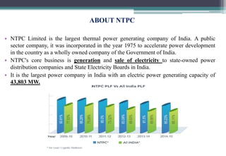
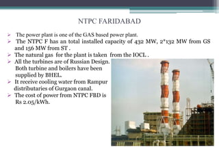
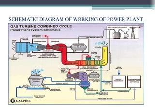
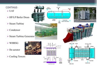
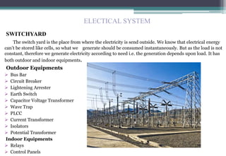
A
SEMINAR ON
INDUSTRIAL TRAINING
AT
NTPC FARIDABAD
SUBMITTED BY :-
ANIL JADON
1204320011 (FINAL YR)
ELECTRICAL ENGG.
HEAD OF DEPARTMENT :
Dr. DEEPAK NAGARIA
HEAD, ELECTRICAL ENGG DEPTT.
INDEX
 ABOUT THE COMPANY
 INTRODUCTION OF NTPC FARIDABAD
 WORKING OF POWER PLANT
 FUEL USED
 ELECTRICAL SYSTEM
 DISTRIBUTION OF ELECTRICITY
 CONTROL AND INSTRUMENTATION
 ADVANTAGES AND PRECAUTION
 CONCLUSION
ABOUT NTPC
• NTPC Limited is the largest thermal power generating company of India. A public
sector company, it was incorporated in the year 1975 to accelerate power development
in the country as a wholly owned company of the Government of India.
• NTPC's core business is generation and sale of electricity to state-owned power
distribution companies and State Electricity Boards in India.
• It is the largest power company in India with an electric power generating capacity of
43,803 MW.
NTPC FARIDABAD
 The power plant is one of the GAS based power plant.
 The NTPC F has an total installed capacity of 432 MW, 2*132 MW from GS
and 156 MW from ST .
 The natural gas for the plant is taken from the IOCL .
 All the turbines are of Russian Design.
Both turbine and boilers have been
supplied by BHEL.
 It receive cooling water from Rampur
distributaries of Gurgaon canal.
 The cost of power from NTPC FBD is
Rs 2.05/kWh.
ANTI-SALIENT FEATURES
 Cost of Generation: Rs. 2.05 / Kwh
 Mode of Operation: Base Load
 Rated Output: 135 MVA for GTG & 191.6 MVA for STG
 Rated Terminal Vol.: 10.5 KV for GTG & 15.75 KV FOR STG
 Rated Speed: 3000 rpm
 Type of Cooling: Air Cooled
 Black start facility:3.5 MW Diesel Generator Set: 2000 rpm
 1kw power = 1975kcal of fuel
OPERATION OF A POWER PLANT
Basic Principle
 As per FARADAY’s Law-“Whenever the amount of magnetic flux linked with a circuit
changes, an EMF is produced in the circuit”.
 Natural gas is pumped into the gas turbine , where it is mixed with air and burned,
converting its chemical energy into heat energy.
 Burning natural gas produces a mixture of gases called the combustion gas.
 The heat makes the combustion gas expand.
 In the enclosed gas turbine, this causes a build-up of pressure.
 The pressure drives the combustion gas over the blades of the gas turbine, causing it to spin,
converting some of the heat energy into mechanical energy.
 A shaft connects the gas turbine to the gas turbine generator , so when the turbine spins, the
generator does too.
 The generator uses an electromagnetic field to convert this mechanical energy into electrical
energy.
SCHEMATIC DIAGRAM OF WORKING OF POWER PLANT
PARTS OF POWER PLANT
 Air Intake System
 Air Filters
 Air Compressor
 Combustion Chamber
 Gas Turbine
 Generator
 Step Up Transformer
CONTINUE-
 UAT
 HP/LP Boiler Drum
 Steam Turbine
 Condensor
 Steam Turbine Generator
 WHRSG
 De-aerator
 Cooling Towers
FUEL USED
 Natural gas
Natural gas is an ideal fuel in gas turbine. It contains primarily Methane (CH4) other
gases are ethane (C2H6), Nitrogen (N2), Carbon dioxide (CO2) and Sulphur(S).
 Naphtha
FGPP works on natural gas but if there is shortage of natural gas then plant is run on
Naphtha. Naphtha as compared to natural gas has less calorific value but there is no
alternate fuel other than Naphtha. It is cheaper than any other fuel and the amount of
flue gases that comesout of the Naphtha can also be sent out to boiler to boil the
water for manufacturing of steam for running the steam turbine.
SWITCHYARD
The switch yard is the place from where the electricity is send outside. We know that electrical energy
can’t be stored like cells, so what we generate should be consumed instantaneously. But as the load is not
constant, therefore we generate electricity according to need i.e. the generation depends upon load. It has
both outdoor and indoor equipments.
Outdoor Equipments
 Bus Bar
 Circuit Breaker
 Lightening Arrester
 Earth Switch
 Capacitor Voltage Transformer
 Wave Trap
 PLCC
 Current Transformer
 Isolators
 Potential Transformer
Indoor Equipments
 Relays
 Control Panels
ELECTICAL SYSTEM
OUTDOOR EQUIPMENTS
 BUS BAR
There are three buses viz. two main buses
(bus 1 and bus 2) and one transfer bus.
The two main buses are further divided
into two sections thus giving us a
total of five buses.
 CIRCUIT BREAKER
An electric power system needs some form of
switchgear in order to operate it safely & efficiently
under both normal and abnormal conditions. Circuit
breaker is an arrangement by which we can break
the circuit or flow of current.
At NTPC FBD uses SF6 CB and GAS CB.
 CVT
The CVT is used for line voltage measurements
on loaded conditions. CVT is used for line voltage
measurements on loaded conditions.
In PT full line voltage and in
CVT reduced voltage is applied.
 LA
Lightening Arrester
 Air Break Earthling Switch
These are used to ground the circuit
and to discharge the CB when CB is in
off condition.
 WAVE TRAP
 PLCC
POWER LINE CARRIER COMMUNICATION
 CT
These are used for stepping down AC current
from higher value to lower value for
measurement, protection and control.
 ISOLATORS
 TRANSFORMERS
CONTROL AND INSTRUMENTATION
 The main functions of the C&I dept. at NTPC Faridabad are:
1. Measurement and display of various parameters.
2. To control the various parameters by Automatic feedback controlling which involves the
taking of decision based on inputs from measurements by the processor.
3. Protection of various equipments (pumps, generators etc.) and workers from hazards by
automatically tripping a cycle when hazardous conditions are reached.
4. Alarm generation in case of a mechanical or an electrical failure.
The Faridabad plant has outsourced its automaton to various companies on a Package Based
Deal.
DISTRIBUTION OF ELECTRICITY
ADVANTAGES
Advantages of using Natural Gas for Generating Electricity
 Less Harmful than Coal or Oil
 Easy Storage and Transport
 Residential Use
 Vehicle Fuel
 Burns Cleaner
 Instant energy
 Precision in Kitchen
 Industrial use
 Abundant.
 Safer
 Versatile
 Cheaper
 Neater
 Used to Produce Electricity
PRECAUTIONS
 Normally, the natural gas is non toxic. However, if having high content of hydrogen
sulfide; the gas can harm people whom inhale the gas. It can irritate skin, eyes, the
respiratory tract and lung.
 Fire and explosion. Natural gas can be flammable when it leaks and mixes with air,
cause fire at a right proportion of air and natural gas and there is a source of ignition or
a flame. It can cause explosion if it accumulates in a confined space such as in the
building where there is not enough ventilation.
CONCLUSION
On completion of my vocational training at NTPC Faridabad, I have come to know about
how the very necessity of our lives now a days i.e. how electricity is generated & what
all processes are needed to generate and run the plant on a 24x7 basis. NTPC Faridabad
is one the plants in India to be under highest load factor for the maximum duration of
time and that to operating at highest plant efficiencies. This plant is an example in terms
of working efficiency and management of resources to all other thermal plants in our
country. The operating of the NTPC as compared to the rest of country is the highest
with 95 % the highest since its inception. The training gave me an opportunity to clear
my concepts from practical point of view with the availability of machinery of diverse
ratings.
Training NTPC

Training NTPC

  • 1.
    A SEMINAR ON INDUSTRIAL TRAINING AT NTPCFARIDABAD SUBMITTED BY :- ANIL JADON 1204320011 (FINAL YR) ELECTRICAL ENGG. HEAD OF DEPARTMENT : Dr. DEEPAK NAGARIA HEAD, ELECTRICAL ENGG DEPTT.
  • 2.
    INDEX  ABOUT THECOMPANY  INTRODUCTION OF NTPC FARIDABAD  WORKING OF POWER PLANT  FUEL USED  ELECTRICAL SYSTEM  DISTRIBUTION OF ELECTRICITY  CONTROL AND INSTRUMENTATION  ADVANTAGES AND PRECAUTION  CONCLUSION
  • 3.
    ABOUT NTPC • NTPCLimited is the largest thermal power generating company of India. A public sector company, it was incorporated in the year 1975 to accelerate power development in the country as a wholly owned company of the Government of India. • NTPC's core business is generation and sale of electricity to state-owned power distribution companies and State Electricity Boards in India. • It is the largest power company in India with an electric power generating capacity of 43,803 MW.
  • 4.
    NTPC FARIDABAD  Thepower plant is one of the GAS based power plant.  The NTPC F has an total installed capacity of 432 MW, 2*132 MW from GS and 156 MW from ST .  The natural gas for the plant is taken from the IOCL .  All the turbines are of Russian Design. Both turbine and boilers have been supplied by BHEL.  It receive cooling water from Rampur distributaries of Gurgaon canal.  The cost of power from NTPC FBD is Rs 2.05/kWh.
  • 5.
    ANTI-SALIENT FEATURES  Costof Generation: Rs. 2.05 / Kwh  Mode of Operation: Base Load  Rated Output: 135 MVA for GTG & 191.6 MVA for STG  Rated Terminal Vol.: 10.5 KV for GTG & 15.75 KV FOR STG  Rated Speed: 3000 rpm  Type of Cooling: Air Cooled  Black start facility:3.5 MW Diesel Generator Set: 2000 rpm  1kw power = 1975kcal of fuel
  • 6.
    OPERATION OF APOWER PLANT Basic Principle  As per FARADAY’s Law-“Whenever the amount of magnetic flux linked with a circuit changes, an EMF is produced in the circuit”.  Natural gas is pumped into the gas turbine , where it is mixed with air and burned, converting its chemical energy into heat energy.  Burning natural gas produces a mixture of gases called the combustion gas.  The heat makes the combustion gas expand.  In the enclosed gas turbine, this causes a build-up of pressure.  The pressure drives the combustion gas over the blades of the gas turbine, causing it to spin, converting some of the heat energy into mechanical energy.  A shaft connects the gas turbine to the gas turbine generator , so when the turbine spins, the generator does too.  The generator uses an electromagnetic field to convert this mechanical energy into electrical energy.
  • 7.
    SCHEMATIC DIAGRAM OFWORKING OF POWER PLANT
  • 8.
    PARTS OF POWERPLANT  Air Intake System  Air Filters  Air Compressor  Combustion Chamber  Gas Turbine  Generator  Step Up Transformer
  • 9.
    CONTINUE-  UAT  HP/LPBoiler Drum  Steam Turbine  Condensor  Steam Turbine Generator  WHRSG  De-aerator  Cooling Towers
  • 10.
    FUEL USED  Naturalgas Natural gas is an ideal fuel in gas turbine. It contains primarily Methane (CH4) other gases are ethane (C2H6), Nitrogen (N2), Carbon dioxide (CO2) and Sulphur(S).  Naphtha FGPP works on natural gas but if there is shortage of natural gas then plant is run on Naphtha. Naphtha as compared to natural gas has less calorific value but there is no alternate fuel other than Naphtha. It is cheaper than any other fuel and the amount of flue gases that comesout of the Naphtha can also be sent out to boiler to boil the water for manufacturing of steam for running the steam turbine.
  • 11.
    SWITCHYARD The switch yardis the place from where the electricity is send outside. We know that electrical energy can’t be stored like cells, so what we generate should be consumed instantaneously. But as the load is not constant, therefore we generate electricity according to need i.e. the generation depends upon load. It has both outdoor and indoor equipments. Outdoor Equipments  Bus Bar  Circuit Breaker  Lightening Arrester  Earth Switch  Capacitor Voltage Transformer  Wave Trap  PLCC  Current Transformer  Isolators  Potential Transformer Indoor Equipments  Relays  Control Panels ELECTICAL SYSTEM
  • 12.
    OUTDOOR EQUIPMENTS  BUSBAR There are three buses viz. two main buses (bus 1 and bus 2) and one transfer bus. The two main buses are further divided into two sections thus giving us a total of five buses.  CIRCUIT BREAKER An electric power system needs some form of switchgear in order to operate it safely & efficiently under both normal and abnormal conditions. Circuit breaker is an arrangement by which we can break the circuit or flow of current. At NTPC FBD uses SF6 CB and GAS CB.
  • 13.
     CVT The CVTis used for line voltage measurements on loaded conditions. CVT is used for line voltage measurements on loaded conditions. In PT full line voltage and in CVT reduced voltage is applied.  LA Lightening Arrester  Air Break Earthling Switch These are used to ground the circuit and to discharge the CB when CB is in off condition.  WAVE TRAP
  • 14.
     PLCC POWER LINECARRIER COMMUNICATION  CT These are used for stepping down AC current from higher value to lower value for measurement, protection and control.  ISOLATORS  TRANSFORMERS
  • 15.
    CONTROL AND INSTRUMENTATION The main functions of the C&I dept. at NTPC Faridabad are: 1. Measurement and display of various parameters. 2. To control the various parameters by Automatic feedback controlling which involves the taking of decision based on inputs from measurements by the processor. 3. Protection of various equipments (pumps, generators etc.) and workers from hazards by automatically tripping a cycle when hazardous conditions are reached. 4. Alarm generation in case of a mechanical or an electrical failure. The Faridabad plant has outsourced its automaton to various companies on a Package Based Deal.
  • 16.
  • 17.
    ADVANTAGES Advantages of usingNatural Gas for Generating Electricity  Less Harmful than Coal or Oil  Easy Storage and Transport  Residential Use  Vehicle Fuel  Burns Cleaner  Instant energy  Precision in Kitchen  Industrial use  Abundant.  Safer  Versatile  Cheaper  Neater  Used to Produce Electricity
  • 18.
    PRECAUTIONS  Normally, thenatural gas is non toxic. However, if having high content of hydrogen sulfide; the gas can harm people whom inhale the gas. It can irritate skin, eyes, the respiratory tract and lung.  Fire and explosion. Natural gas can be flammable when it leaks and mixes with air, cause fire at a right proportion of air and natural gas and there is a source of ignition or a flame. It can cause explosion if it accumulates in a confined space such as in the building where there is not enough ventilation.
  • 19.
    CONCLUSION On completion ofmy vocational training at NTPC Faridabad, I have come to know about how the very necessity of our lives now a days i.e. how electricity is generated & what all processes are needed to generate and run the plant on a 24x7 basis. NTPC Faridabad is one the plants in India to be under highest load factor for the maximum duration of time and that to operating at highest plant efficiencies. This plant is an example in terms of working efficiency and management of resources to all other thermal plants in our country. The operating of the NTPC as compared to the rest of country is the highest with 95 % the highest since its inception. The training gave me an opportunity to clear my concepts from practical point of view with the availability of machinery of diverse ratings.