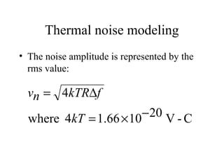
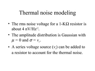
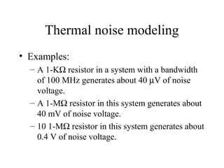
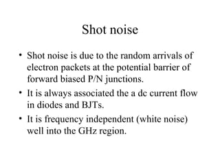
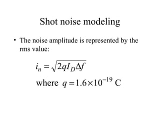
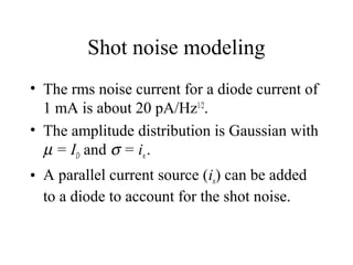
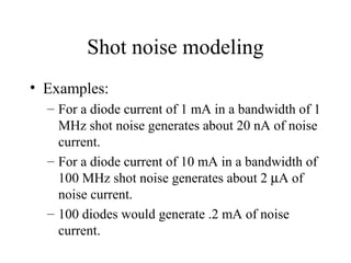
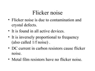
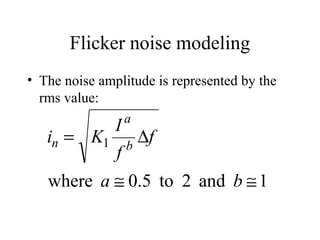
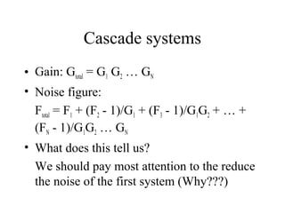
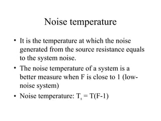
Electrical Noise
Wang C. Ng
Nature of electrical noise
• Noise is caused by the small current and
voltage fluctuations that are generated
internally.
• Noise is basically due to the discrete nature
of electrical charges.
• Externally generated noise is not considered
here.
Why study noise?
• It sets the lower limit for the detectable
signals.
• It sets the upper limit for system gains.
• Develop mathematical models to take the
effects of noise into account when
analyzing electrical circuits/systems.
• Find ways to reduce noise.
Thermal noise
• Due to random motion of electrons.
• It is ubiquitous (resistors, speakers,
microphones, antennas, …)
• It is directly proportional to absolute
temperature.
• White noise - Frequency independent up to
1013
Hz.
Thermal noise modeling
• The noise amplitude is represented by the
rms value:
C-V201066.14where
4
−×=
∆=
kT
fkTRnv
Thermal noise modeling
• The rms noise voltage for a 1-KΩ resistor is
about 4 nV/Hz1/2
.
• The amplitude distribution is Gaussian with
µ = 0 and σ = vn.
• A series voltage source (vn) can be added to
a resistor to account for the thermal noise.
Thermal noise modeling
• Examples:
– A 1-KΩ resistor in a system with a bandwidth
of 100 MHz generates about 40 µV of noise
voltage.
– A 1-MΩ resistor in this system generates about
40 mV of noise voltage.
– 10 1-MΩ resistor in this system generates about
0.4 V of noise voltage.
Shot noise
• Shot noise is due to the random arrivals of
electron packets at the potential barrier of
forward biased P/N junctions.
• It is always associated the a dc current flow
in diodes and BJTs.
• It is frequency independent (white noise)
well into the GHz region.
Shot noise modeling
• The noise amplitude is represented by the
rms value:
C106.1where
2
19−
×=
∆=
q
fqIi Dn
Shot noise modeling
• The rms noise current for a diode current of
1 mA is about 20 pA/Hz1/2
.
• The amplitude distribution is Gaussian with
µ = ID and σ = in.
• A parallel current source (in) can be added
to a diode to account for the shot noise.
Shot noise modeling
• Examples:
– For a diode current of 1 mA in a bandwidth of 1
MHz shot noise generates about 20 nA of noise
current.
– For a diode current of 10 mA in a bandwidth of
100 MHz shot noise generates about 2 µA of
noise current.
– 100 diodes would generate .2 mA of noise
current.
Flicker noise
• Flicker noise is due to contamination and
crystal defects.
• It is found in all active devices.
• It is inversely proportional to frequency
(also called 1/f noise) .
• DC current in carbon resistors cause flicker
noise.
• Metal film resistors have no flicker noise.
Flicker noise modeling
• The noise amplitude is represented by the
rms value:
1and2to5.0where
1
≅≅
∆=
ba
f
f
I
Ki b
a
n
Flicker noise modeling
• The constant K1 is device dependent and
must be determined experimentally.
• The amplitude distribution is non-Gaussian.
• It is often the dominating noise factor in the
low-frequency region.
• It can be described in more details with
fractal theory.
Other noise types
• Burst noise (popcorn noise):
System Noise Analysis
Wang Ng
Introduction
• Noise sources can be added to a device
models to represent the effect of noise.
• We need a means to characterize the noise
performance of a system (black box).
• Noise figure
• Noise temperature
Noise figure
• Used for resistive source impedance.
• Most communication systems have a 50-Ω
source impedance (Thevenin equivalent).
• Signal-to-noise (S/N) ratio
• Noise figure: F = (S/N)in / (S/N)out
• F is a direct measure of the S/N ratio
degradation caused by the system.
Noise figure calculations
• For an ideal (noiseless) amplifier:
Sout = G Sin
Nout = G Nin
• For a real system:
F = (Sin/Nin)(Nout/Sout) = Nout/GNin
or F = (Total noise)/(Noise due to input)
• F in in general frequency dependent.
System noise
• Internally generated noise can be computed
from:
Nsys = (F - 1)GNin
since Nout = Nsys + GNin
Cascade systems
• Gain: Gtotal = G1 G2 … GN
• Noise figure:
Ftotal = F1 + (F2 - 1)/G1 + (F3 - 1)/G1G2 + … +
(FN - 1)/G1G2 … GN
• What does this tell us?
We should pay most attention to the reduce
the noise of the first system (Why???)
Noise temperature
• It is the temperature at which the noise
generated from the source resistance equals
to the system noise.
• The noise temperature of a system is a
better measure when F is close to 1 (low-
noise system)
• Noise temperature: Tn = T(F-1)
Radiometer
• A modern radiometer can measure noise
temperature variation down to 100th or
even less in °K.
• This instrument can be used for remote
sensing/imaging.
• Possible extra credit presentation.
Summary
• System noise measure: Noise figure and
noise temperature
• Internal noise calculation
• Cascade system noise
• First stage noise

Noise

  • 1.
  • 2.
    Nature of electricalnoise • Noise is caused by the small current and voltage fluctuations that are generated internally. • Noise is basically due to the discrete nature of electrical charges. • Externally generated noise is not considered here.
  • 3.
    Why study noise? •It sets the lower limit for the detectable signals. • It sets the upper limit for system gains. • Develop mathematical models to take the effects of noise into account when analyzing electrical circuits/systems. • Find ways to reduce noise.
  • 4.
    Thermal noise • Dueto random motion of electrons. • It is ubiquitous (resistors, speakers, microphones, antennas, …) • It is directly proportional to absolute temperature. • White noise - Frequency independent up to 1013 Hz.
  • 5.
    Thermal noise modeling •The noise amplitude is represented by the rms value: C-V201066.14where 4 −×= ∆= kT fkTRnv
  • 6.
    Thermal noise modeling •The rms noise voltage for a 1-KΩ resistor is about 4 nV/Hz1/2 . • The amplitude distribution is Gaussian with µ = 0 and σ = vn. • A series voltage source (vn) can be added to a resistor to account for the thermal noise.
  • 7.
    Thermal noise modeling •Examples: – A 1-KΩ resistor in a system with a bandwidth of 100 MHz generates about 40 µV of noise voltage. – A 1-MΩ resistor in this system generates about 40 mV of noise voltage. – 10 1-MΩ resistor in this system generates about 0.4 V of noise voltage.
  • 8.
    Shot noise • Shotnoise is due to the random arrivals of electron packets at the potential barrier of forward biased P/N junctions. • It is always associated the a dc current flow in diodes and BJTs. • It is frequency independent (white noise) well into the GHz region.
  • 9.
    Shot noise modeling •The noise amplitude is represented by the rms value: C106.1where 2 19− ×= ∆= q fqIi Dn
  • 10.
    Shot noise modeling •The rms noise current for a diode current of 1 mA is about 20 pA/Hz1/2 . • The amplitude distribution is Gaussian with µ = ID and σ = in. • A parallel current source (in) can be added to a diode to account for the shot noise.
  • 11.
    Shot noise modeling •Examples: – For a diode current of 1 mA in a bandwidth of 1 MHz shot noise generates about 20 nA of noise current. – For a diode current of 10 mA in a bandwidth of 100 MHz shot noise generates about 2 µA of noise current. – 100 diodes would generate .2 mA of noise current.
  • 12.
    Flicker noise • Flickernoise is due to contamination and crystal defects. • It is found in all active devices. • It is inversely proportional to frequency (also called 1/f noise) . • DC current in carbon resistors cause flicker noise. • Metal film resistors have no flicker noise.
  • 13.
    Flicker noise modeling •The noise amplitude is represented by the rms value: 1and2to5.0where 1 ≅≅ ∆= ba f f I Ki b a n
  • 14.
    Flicker noise modeling •The constant K1 is device dependent and must be determined experimentally. • The amplitude distribution is non-Gaussian. • It is often the dominating noise factor in the low-frequency region. • It can be described in more details with fractal theory.
  • 15.
    Other noise types •Burst noise (popcorn noise):
  • 16.
  • 17.
    Introduction • Noise sourcescan be added to a device models to represent the effect of noise. • We need a means to characterize the noise performance of a system (black box). • Noise figure • Noise temperature
  • 18.
    Noise figure • Usedfor resistive source impedance. • Most communication systems have a 50-Ω source impedance (Thevenin equivalent). • Signal-to-noise (S/N) ratio • Noise figure: F = (S/N)in / (S/N)out • F is a direct measure of the S/N ratio degradation caused by the system.
  • 19.
    Noise figure calculations •For an ideal (noiseless) amplifier: Sout = G Sin Nout = G Nin • For a real system: F = (Sin/Nin)(Nout/Sout) = Nout/GNin or F = (Total noise)/(Noise due to input) • F in in general frequency dependent.
  • 20.
    System noise • Internallygenerated noise can be computed from: Nsys = (F - 1)GNin since Nout = Nsys + GNin
  • 21.
    Cascade systems • Gain:Gtotal = G1 G2 … GN • Noise figure: Ftotal = F1 + (F2 - 1)/G1 + (F3 - 1)/G1G2 + … + (FN - 1)/G1G2 … GN • What does this tell us? We should pay most attention to the reduce the noise of the first system (Why???)
  • 22.
    Noise temperature • Itis the temperature at which the noise generated from the source resistance equals to the system noise. • The noise temperature of a system is a better measure when F is close to 1 (low- noise system) • Noise temperature: Tn = T(F-1)
  • 23.
    Radiometer • A modernradiometer can measure noise temperature variation down to 100th or even less in °K. • This instrument can be used for remote sensing/imaging. • Possible extra credit presentation.
  • 24.
    Summary • System noisemeasure: Noise figure and noise temperature • Internal noise calculation • Cascade system noise • First stage noise