The document is a comprehensive user manual for Netsim, detailing its introduction, installation, and various network simulation types. It covers setting up scenarios, traffic generation, advanced features, and troubleshooting issues. Additionally, the document includes guidelines on using custom code and integrating with external tools like MATLAB.


![42
Consider the following scenarios:
If you create a network with two wired nodes and a switch, the IP addresses are assigned as
10.0.1.2 and 10.0.1.3 for the two wired nodes. The default subnet mask is assigned to be
255.255.0.0. It can be edited to 255.0.0.0 (Class A) or 255.255.255.0 (Class C) subnet masks.
Both the nodes are in the same network (10.0.0.0).
Similarly, if you create a network with a router and two wired nodes, the IP addressed are
assigned as 11.1.1.2 and 11.2.1.2 for the two wired nodes. The subnet mask is default as in
above case, i.e., 255.255.0.0. The IP address of the router is 11.1.1.1 and 11.2.1.1
respectively for the two interfaces. Both the nodes are in different networks (11.1.0.0 and
11.2.0.0) in this case.
The same logic is extended as the number of devices is increased.
3.1.8 SINR, BER and Propagation models for 802.11 a, b, g and n
3.1.8.1 Received Power Calculation
The received power can be expressed as
[Prec]dbm = 10log10 (Pt) + [GT] + [GR] + 20log10 (λ/4πd0) + 10ηlog (d0/d) + Pshadow loss + Pfading
Where Pt = Power Transmitted (in mwatts)
GT=Gain of the transmitting antenna (in dB)
GR=Gain of the receiving antenna (in dB)
λ = Wavelength (in meters)
d0= Reference distance (at which the path loss inherits free space path loss)
η = Path loss exponent (ranges between 2 to 5)
Pshadow loss = Power due to Shadowing (in dB)
Pfading = Power due to Fading (in dB)
The code for calculating the received power is included in the file PropagationModel.c, path
for the file is NetSim StandardsrcSimulationIEEE802_11.](https://image.slidesharecdn.com/netsimusermanual-161103121740/85/NetSim-User-Manual-42-320.jpg)


![71
Therefore, SINR in dBm is calculated as:
SINR (in dBm) = ( )
Bit Error Rate (BER) Calculation:
The bit error rate (BER) is the number of bit errors divided by the total number of transferred
bits during a studied time interval. The BER results were obtained using the analytical model
from IEEE standard 802.15.2-2003 [B9]. The calculation follows the approach outlined in
5.3.2 of that standard.
BER = ( ) ( ) ∑ ( )
( ( ))
Where SINR = Signal-to-Interference-plus-Noise Ratio. BER should be between 0 and 1.
Propagation Loss:
Three different and mutually independent propagation phenomena influence the power of the
received signal: path loss, shadowing and multipath fading.
Shadowing:
Slow shadowing in wireless network is the attenuation caused by buildings or any obstacles
between a transmitter and a receiver. In the model with shadowing, the shadowing value Xσ,
typically defined in dB, is added to (or subtracted from) the average received power. Xσ is a
zero means Gaussian distributed random variable with standard deviation σ.
The Probability Density Function (PDF) of the lognormal distribution is:
The default value for standard deviation is chosen as 5 dB.](https://image.slidesharecdn.com/netsimusermanual-161103121740/85/NetSim-User-Manual-71-320.jpg)
![72
Path Loss:
Pathloss is the reduction in power density of an electromagnetic wave as it propagates
through space. Path loss may be due to many effects, such as free-space loss, refraction,
diffraction, reflection, aperture-medium coupling loss, and absorption.
Path loss can be represented by the path loss exponent, whose value is normally in the range
of 2 to 4, where 2 is for propagation in free space and 4 is for relatively loss environments. In
NetSim, the default value for path loss exponent is taken as 2.
Path loss is usually expressed in dB. In its simplest form, the path loss can be calculated
using the formula
Where L is the path loss in decibels, is the path loss exponent, d is the distance between the
transmitter and the receiver, usually measured in meters, and C is a constant which accounts
for system losses.
A simplified formula for the path loss between two isotropic antennas in free space:
L (in dBm) = ( )
Where L is the path loss in decibels, λ is the wavelength and d is the transmitter-receiver
distance in the same units as the wavelength.
Calculation of Received Power:
In general,
( ) ( ) ( ) ( ) ( )
The path loss model used is described in IEEE Standard 802.15.2-2003[B9], which stipulates
a two-segment function with a path loss exponent of 2.0 for the first 8 m and then a path loss
exponent of 3.3 thereafter. The formula given in IEEE Standard 802.15.2 is shown in
Equation (E.1).](https://image.slidesharecdn.com/netsimusermanual-161103121740/85/NetSim-User-Manual-72-320.jpg)


![81
P (in mW) =
( )
Therefore, SINR in dBm is calculated as:
SINR (in dBm) = ( )
Bit Error Rate (BER) Calculation:
The bit error rate (BER) is the number of bit errors divided by the total number of transferred
bits during a studied time interval. The BER results were obtained using the analytical model
from IEEE standard 802.15.2-2003 [B9]. The calculation follows the approach outlined in
5.3.2 of that standard.
BER = ( ) ( ) ∑ ( )
( ( ))
Where SINR = Signal-to-Interference-plus-Noise Ratio. BER should be between 0 and 1.
Propagation Loss:
Three different and mutually independent propagation phenomena influence the power of the
received signal: path loss, shadowing and multipath fading.
Shadowing:
Slow shadowing in wireless network is the attenuation caused by buildings or any obstacles
between a transmitter and a receiver. In the model with shadowing, the shadowing value Xσ,
typically defined in dB, is added to (or subtracted from) the average received power. Xσ is a
zero means Gaussian distributed random variable with standard deviation σ.
The Probability Density Function (PDF) of the lognormal distribution is:
The default value for standard deviation is chosen as 5 dB.](https://image.slidesharecdn.com/netsimusermanual-161103121740/85/NetSim-User-Manual-81-320.jpg)
![82
Path Loss:
Pathloss is the reduction in power density of an electromagnetic wave as it propagates
through space. Path loss may be due to many effects, such as free-space loss, refraction,
diffraction, reflection, aperture-medium coupling loss, and absorption.
Path loss can be represented by the path loss exponent, whose value is normally in the range
of 2 to 4, where 2 is for propagation in free space and 4 is for relatively loss environments. In
NetSim, the default value for path loss exponent is taken as 2.
Path loss is usually expressed in dB. In its simplest form, the path loss can be calculated
using the formula
Where L is the path loss in decibels, is the path loss exponent, d is the distance between the
transmitter and the receiver, usually measured in meters, and C is a constant which accounts
for system losses.
A simplified formula for the path loss between two isotropic antennas in free space:
L (in dBm) = ( )
Where L is the path loss in decibels, λ is the wavelength and d is the transmitter-receiver
distance in the same units as the wavelength.
Calculation of Received Power:
In general,
( ) ( ) ( ) ( ) ( )
The path loss model used is described in IEEE Standard 802.15.2-2003[B9], which stipulates
a two-segment function with a path loss exponent of 2.0 for the first 8 m and then a path loss
exponent of 3.3 thereafter. The formula given in IEEE Standard 802.15.2 is shown in
Equation (E.1).](https://image.slidesharecdn.com/netsimusermanual-161103121740/85/NetSim-User-Manual-82-320.jpg)


![118
Plugging in a few values, we find that:
The probability of generating a packet within the next 0.05 seconds is F(0.05)≈ 0.63
The probability of generating a packet within 1 second is F(1)≈ 0.999999998
In particular, note that after 0.05 seconds – the prescribed average time between packets – the
probability is F(0.05)≈ 0.63 .
Generating Poisson arrivals in NetSim
We simply write a function to determine the exact amount of time until the next packet. This
function should return random numbers, but not the uniform kind of random number
produced by most generators. We want to generate random numbers in a way that follows our
exponential distribution.
Given that the inverse of the exponential function is ln, it‟s pretty easy to write this
analytically, where U is the random value between 0 and 1:
Next Time when a packet is generated =−ln(1- RandNo) / λ
This is exactly the code used in NetSim, and this is available in the source C file in
../NetSim_Standard/Simulation/Application/Distribution.c. In the case exponential
distribution, you would see
case Distribution_Exponential: /*Exponential Distribution Function*/
fFirstArg = args[0];
nRandOut = fnRandomNo(10000000, &fRand, uSeed, uSeed1);
fRandomNumber = (double) (fRand);
fFirstArg = 1 / fFirstArg;
*fDistOut = (double) -(1 / fFirstArg)* (double) logl(1 - fRandomNumber);
The simple way of selecting this via the UI is to selecting exponential distribution for inter-
arrival time when modelling application properties.](https://image.slidesharecdn.com/netsimusermanual-161103121740/85/NetSim-User-Manual-118-320.jpg)


![164
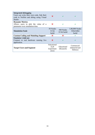
7.2.2 Introducing Node Failure in MANET
Objective: Node failure using MANET-DSR using Device Id.
Implementation: Identify the Device ID of the particular node to be failed.
Step 1: Create a file with the name NodeFailure.txt inside the bin folder of NetSim
installation directory. The file will contain two columns: one being the Node ID of the device
to be failed and other being the failure time (in microseconds).
For example, to fail Node Id 2 from 10th
sec onwards and fail Node Id 1 from 90th
sec
onwards, the NodeFailure.txt file will be as follows:
Step 2: Go to DSR.c in DSR protocol.
Step 3: The function fn_NetSim_DSR_Init() will execute before the protocol execution
starts. So in this function, we will read the NodeFailure.txt and save information regarding
which nodes will fail at which time. Add the following code inside the specified function.
int i;
FILE *fp1;
char *pszFilepath;
char pszConfigInput[1000];
pszFilepath = fnpAllocateMemory(36,sizeof(char)*50);
strcpy(pszFilepath,pszAppPath);
strcat(pszFilepath,"/NodeFailure.txt");
fp1 = fopen(pszFilepath,"r");
i=0;
if(fp1)
{
while(fgets(pszConfigInput,500,fp1)!= NULL)
{
sscanf(pszConfigInput,"%d %d",&NodeArray[i],&TimeArray[i]);
i+=1;
}
}
fclose(fp1);](https://image.slidesharecdn.com/netsimusermanual-161103121740/85/NetSim-User-Manual-164-320.jpg)
![165
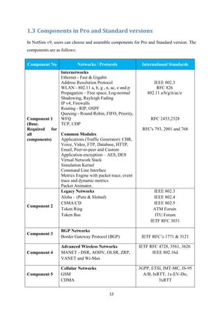
Step 4: The fn_NetSim_DSR_Run( ) is the main function to handle all the protocol
functionalities. So add the following code to the function at the start.
int i,nFlag=1;
if(nFlag)
{
for(i=0;i<100;i++)
if((pstruEventDetails->nDeviceId== NodeArray[i])&&(pstruEventDetails-
>dEventTime >= TimeArray[i]))
{
pstruEventDetails->nInterfaceId = 0;
pstruEventDetails->pPacket=NULL;
return 0;
}
}
Step 5: Add the following code inside DSR.h header file
//Node failure model
int NodeArray[200];
int TimeArray[200];
Step 6: Create DLL and Link the DLL to the NetSim as explained in Section 7.1.
Step 7: Create a scenario in MANET and run the simulation. User can utilize Packet
Animation to check the node failure (i.e. no packets are forwarded by failed nodes) after the
mentioned time.](https://image.slidesharecdn.com/netsimusermanual-161103121740/85/NetSim-User-Manual-165-320.jpg)
![166
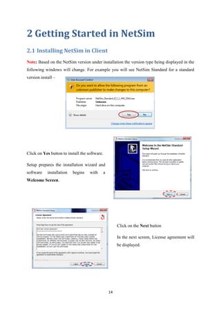
7.2.3 Transferring file from source to destination in WSN
Objective: Transferring a real file from source node to destination node in WSN
Implementation: The code modifications to transfer file from Sensor to Sink node are
described here:
1. Open NetSim.sln in Visual Studio and add the following modifications.
2. The modified files are in Zigbee: Sensor.c and 802_15_4.h
3. In 802_15_4.h add the following line of code
#define _FILE_SEND_ //Uncomment to transfer file
4. In Sensor.c, the code must be modified at specified places in red color. Add the
modified code:
#include "main.h"
#include "List.h"
#include "802_15_4.h"
#define MAX_PAYLOAD 70
int fn_NetSim_FindAgentPos(double* dXPos, double* dYPos, int nAgentId,double
dSensingTime,AGENT** pstruAgent);
double fn_Sensor_CalculateDistance(POS_2D* pstruPos1, POS_2D* pstruPos2);
#ifdef _FILE_SEND_
typedef struct file_info
{
char Packet[100];
long len;
int Packet_Id;
_ele* ele;
}FILE_INFO,*PFILE_INFO;
#define FILE_INFO_ALLOC()
(PFILE_INFO)list_alloc(sizeof(FILE_INFO),offsetof(FILE_INFO,ele))
PFILE_INFO fileinfo=NULL;
static int nPacketId=0;
char file_name[100][50] = {"send.txt"};
char outfile_name[100][50] = {"receive.txt"};
int fnWriteFile(int PacketId)
{
char *packet;
static FILE *file_receive=NULL;
PFILE_INFO file_rec=fileinfo;
size_t siz;
if(!file_receive)
file_receive = fopen(outfile_name[0],"wb");
while(file_rec)
{
if(file_rec->Packet_Id == PacketId)
{](https://image.slidesharecdn.com/netsimusermanual-161103121740/85/NetSim-User-Manual-166-320.jpg)
![167
//fprintf(stderr,"file written. size = %dn",file_rec-
>len);
packet = file_rec->Packet;
siz = file_rec->len;
fwrite(packet,sizeof(char),siz,file_receive);
}
file_rec=LIST_NEXT(file_rec);
}
fflush(file_receive);
return 0;
}
int fnsendfile(NETSIM_ID nSensorLoop)
{
NetSim_PACKET *PstruPacket;
FILE *file_transfer;
size_t siz;
long file_size;
long n;
PFILE_INFO file;
if(file_name[nSensorLoop-1] && *file_name[nSensorLoop-1])
file_transfer = fopen(file_name[nSensorLoop-1],"rb");
else
return -1;
if(!file_transfer)
{
perror(file_name[nSensorLoop-1]);
return -1;
}
fseek(file_transfer,0,SEEK_END);
file_size = ftell(file_transfer);
rewind(file_transfer);
n = file_size;
while(n>0)
{
char str[MAX_PAYLOAD+10];
fprintf(stderr,"Size left = %dn",n);
if(n>=MAX_PAYLOAD)
{
siz = fread(str,sizeof(char),MAX_PAYLOAD,file_transfer);
}
else
{
siz = fread(str,sizeof(char),n,file_transfer);
}
n-=siz;
//Add application out to tramit the position
//Generate the packet
PstruPacket = fn_NetSim_Packet_CreatePacket(5);
PstruPacket->dEventTime = pstruEventDetails->dEventTime;
PstruPacket->nDestinationId = nGlobalPANCoordinatorId;
PstruPacket->nPacketId = ++nPacketId;
PstruPacket->nPacketStatus = 0;
PstruPacket->nPacketType = PacketType_Custom;](https://image.slidesharecdn.com/netsimusermanual-161103121740/85/NetSim-User-Manual-167-320.jpg)
![168
PstruPacket->nPacketPriority = Priority_Low;
PstruPacket->nQOS =(NETSIM_ID)QOS_BE;
PstruPacket->nSourceId = (NETSIM_ID)nSensorLoop;
//Update the Transport layer information
PstruPacket->pstruTransportData->nSourcePort = SOURCEPORT;
PstruPacket->pstruTransportData->nDestinationPort =
DESTINATIONPORT;
//Update the Network layer information
PstruPacket->pstruNetworkData->szSourceIP =
IP_COPY(fn_NetSim_Stack_GetFirstIPAddressAsId((NETSIM_ID)nSensorLoop,0));
PstruPacket->pstruNetworkData->szDestIP =
IP_COPY(fn_NetSim_Stack_GetFirstIPAddressAsId(PstruPacket-
>nDestinationId,0));
PstruPacket->pstruNetworkData->nTTL = MAX_TTL;
//Update the Application layer information
//For transferring file from Sensor to sink node
//70 bytes at a time
file =FILE_INFO_ALLOC();
memcpy(file->Packet,str,siz);
file->Packet_Id = PstruPacket->nPacketId;
file->len = siz;
LIST_ADD_LAST((void**)&fileinfo,file);
PstruPacket->szPayload = NULL;
PstruPacket->pstruAppData->dPayload = siz;
PstruPacket->pstruAppData->dOverhead = 0;
PstruPacket->pstruAppData->dPacketSize = PstruPacket-
>pstruAppData->dPayload + PstruPacket->pstruAppData->dOverhead;
PstruPacket->pstruAppData->dArrivalTime = pstruEventDetails-
>dEventTime;
PstruPacket->pstruAppData->dEndTime = pstruEventDetails-
>dEventTime;
PstruPacket->pstruAppData->dStartTime = pstruEventDetails-
>dEventTime;
if(NETWORK->ppstruDeviceList[nSensorLoop-1]-
>pstruTransportLayer->isUDP)
PstruPacket->pstruTransportData-
>nTransportProtocol=TX_PROTOCOL_UDP;
else if(NETWORK->ppstruDeviceList[nSensorLoop-1]-
>pstruTransportLayer->isTCP)
PstruPacket->pstruTransportData-
>nTransportProtocol=TX_PROTOCOL_TCP;
else
PstruPacket->pstruTransportData->nTransportProtocol=0;
if(NETWORK->ppstruDeviceList[nSensorLoop-1]-
>pstruSocketInterface->pstruSocketBuffer[0]->pstruPacketlist==NULL)
{
fn_NetSim_Packet_AddPacketToList((NETWORK-
>ppstruDeviceList[nSensorLoop-1]->pstruSocketInterface-
>pstruSocketBuffer[0]),PstruPacket,3);
pstruEventDetails->dPacketSize=PstruPacket-
>pstruAppData->dPacketSize;
pstruEventDetails->nDeviceType = SENSOR;
pstruEventDetails->nApplicationId=0;](https://image.slidesharecdn.com/netsimusermanual-161103121740/85/NetSim-User-Manual-168-320.jpg)
![169
pstruEventDetails->nProtocolId=PstruPacket-
>pstruTransportData->nTransportProtocol;
pstruEventDetails->nDeviceId=(NETSIM_ID)nSensorLoop;
pstruEventDetails->nInterfaceId=0;
pstruEventDetails->nEventType=TRANSPORT_OUT_EVENT;
pstruEventDetails->nSubEventType=0;
pstruEventDetails->pPacket=NULL;
fnpAddEvent(pstruEventDetails);
}
else
{
fn_NetSim_Packet_AddPacketToList((NETWORK-
>ppstruDeviceList[nSensorLoop-1]->pstruSocketInterface-
>pstruSocketBuffer[0]),PstruPacket,2);
}
}
fclose(file_transfer);
return 0;
}
#endif
/** In this function the sensors sense the agent, creates a packet and
forwards it to sink node.*/
int fn_NetSim_Zigbee_SensorEvent(int nSensorLoop,NETSIM_ID
nGlobalPANCoordinatorId,AGENT** pstruAgent,SENSORS* pstru_Sensor,METRICS**
pstruMetrics,NetSim_EVENTDETAILS* pstruEventDetails)
{
int nFlag = 0;
static int nPacketId;
char str[500];
int nAgentLoop;
POS_2D* pstruPos;
double dDistance;
POS_2D* pstruTemppos;
NetSim_PACKET *PstruPacket;
#ifdef _FILE_SEND_
fnsendfile((NETSIM_ID)nSensorLoop);
return 0;
#endif
pstruPos = (POS_2D*)fnpAllocateMemory(sizeof(POS_2D),1);
pstruTemppos = (POS_2D*)fnpAllocateMemory(sizeof(POS_2D),1);
for(nAgentLoop =0;nAgentLoop<MAXAGENT;nAgentLoop++)
{
if(pstruAgent[nAgentLoop] == NULL)
continue;
5. In 802_15_4.c , the code must be modified at specified places in red color. Add the
modified code:
case MAC_IN_EVENT:
{
.
.
.](https://image.slidesharecdn.com/netsimusermanual-161103121740/85/NetSim-User-Manual-169-320.jpg)
![170
if(pstruPacket->nControlDataType/100 != MAC_PROTOCOL_IEEE802_15_4)
{
//Prepare the Network in event details
pstruPacket->pstruMacData->dOverhead -= 5;
pstruPacket->pstruMacData->dPacketSize = pstruPacket-
>pstruMacData->dPayload + pstruPacket->pstruMacData->dOverhead;
pstruEventDetails->dPacketSize = pstruPacket->pstruMacData-
>dPacketSize;
pstruEventDetails->pPacket = pstruPacket;
pstruEventDetails->nEventType = NETWORK_IN_EVENT;
pstruEventDetails->nSubEventType = 0;
pstruEventDetails->nProtocolId =
fn_NetSim_Stack_GetNWProtocol(pstruEventDetails->nDeviceId);
//Add Network in event
fnpAddEvent(pstruEventDetails);
#ifdef _FILE_SEND_
if(pstruPacket->nPacketType == PacketType_Custom)
fnWriteFile(pstruPacket->nPacketId);
#endif
}
else if(pstruPacket->nControlDataType == BEACON_FRAME)
{ ...
6. Copy the input file (file to be transferred) in NetSim bin folder (“C:Program
FilesNetSim Standardbin”) and rename it as send.txt.
7. In Sensor.c, user can optionally edit the name of the input file in file_name[] and
output file in outfile_name[] in the code. For example, currently it is receive.txt for
output file.
8. Build Zigbee (Please refer section 7.1) and link the dll to bin folder of NetSim. Take
care to rename the original libZigbee.dll so as to preserve the original binaries of
NetSim
9. Next, to run the code, follow these steps:
In this section we create a sample scenario to transfer file from Sensor to Sink Node in WSN:
Step 1: Create a scenario in NetSim as follows. Make sure the
sensor is dropped first on the environment
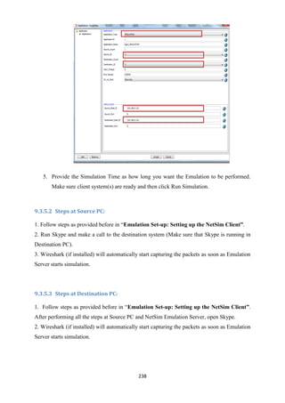
Step 2: Run the simulation. (Make sure the input file to be
transferred is present in bin folder of NetSim).
Step 3: Output file should be present in bin folder of NetSim with
the name receive.txt defined earlier in outfile_name[] in Sensor.c.
Note: Due to retransmissions and errors, sometimes the output file is not reproduced
correctly. To get exact file, user has to enable TCP (WSN works on UDP).](https://image.slidesharecdn.com/netsimusermanual-161103121740/85/NetSim-User-Manual-170-320.jpg)


![195
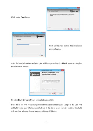
8.3 Mobility Models in NetSim
Mobility models represent the movement of mobile user, and how their location, velocity and
acceleration change over time. Such models are frequently used for simulation purposes
when new communication or navigation techniques are investigated, or to evaluate the
performance of mobile wireless systems and the algorithms and protocols at the basis of
them. Typical mobility models provided in NetSim are as follows:
8.3.1 Random Walk mobility model
It is a simple mobility model based on random directions and speeds. In this mobility model,
a mobile node moves from its current location to a new location by randomly choosing a
direction and speed in which to travel. The new speed and direction are both chosen from
pre-defined ranges. Each movement in the Random Walk Mobility Model occurs in either a
constant time interval or a constant distance traveled, at the end of which a new direction and
speed are calculated.
8.3.2 Random Waypoint Mobility Model
It includes pause time between changes in direction and/or speed. A mobile node begins by
staying in one location for a certain period of time (i.e., a pause time). Once this time expires,
the mobile node chooses a random destination in the simulation area and a speed that is
uniformly distributed between [minspeed, maxspeed]. The mobile node then travels toward
the newly chosen destination at the selected speed. Upon arrival, the mobile node pauses for a
specified time period before starting the process again.
8.3.3 Group mobility
It is a model which describes the behavior of mobile nodes as they move together. i.e. the
sensors having common group id will move together.
8.3.4 File Based Mobility
In File Based Mobility, users can write their own custom mobility models and define the
movement of the mobile users. The name of the trace file generated should be kept as
mobility.txt and it should be in the NetSim Mobility File format.](https://image.slidesharecdn.com/netsimusermanual-161103121740/85/NetSim-User-Manual-195-320.jpg)


![198
8.4 Interfacing MATLAB with NetSim
8.4.1 Implement Nakagami Distribution of MATLAB in NetSim without
using .m file
In this example we will replace the default Rayleigh Fading (part of the path loss calculation)
used in NetSim, with a Fading Power calculated using the Nakagami Distribution from
MATLAB
Procedure:
1) Create a MATLAB_Interface.c file inside the IEEE802_11 folder which can be found
in the path <NetSim_Install_Direcotry>/src/Simulation/. Write the following code inside the
MATLAB_Interface.c file:-
/*
*
* This is a simple program that illustrates how to call the MATLAB
* Engine functions from NetSim C Code.
*
*/
#include <windows.h>
#include <stdlib.h>
#include <stdio.h>
#include <string.h>
#include "engine.h"
#include "mat.h"
#include "mex.h"
char buf[100];
Engine *ep;
int status;
mxArray *h=NULL, *i=NULL, *j=NULL,*k=NULL;
mxArray *out;
double *result;
double fn_netsim_matlab_init()
{
/*
* Start the MATLAB engine
*/
if (!(ep = engOpen(NULL))) {
MessageBox ((HWND)NULL, (LPCWSTR)"Can't start MATLAB engine",
(LPCWSTR) "MATLAB_Interface.c", MB_OK);
exit(-1);
}
engEvalString(ep,"desktop");
return 0;
}
double fn_netsim_matlab_run()](https://image.slidesharecdn.com/netsimusermanual-161103121740/85/NetSim-User-Manual-198-320.jpg)
![199
{
//write your own implementation here
int nakagami_shape=5,nakagami_scale=2;
engPutVariable(ep,"h",h);
sprintf(buf,"h=ProbDistUnivParam('nakagami',[%d
%d])",nakagami_shape,nakagami_scale);
status=engEvalString(ep,buf);
engPutVariable(ep,"i",i);
sprintf(buf,"i=random(h,1)");
status=engEvalString(ep,buf);
out=engGetVariable(ep,"i");
result=mxGetPr(out);
return *result;
}
double fn_netsim_matlab_finish()
{
status=engEvalString(ep,"exit");
return 0;
}
2) Now open IEEE802_11 project file, inside the IEEE802_11 folder.](https://image.slidesharecdn.com/netsimusermanual-161103121740/85/NetSim-User-Manual-199-320.jpg)


![206
16) Now replace the newly built libIEEE802.11.dll from the DLL folder, into the NetSim
bin folder. Please ensure you rename the original libIEEE802.11.dll file to retain a copy of
the original file.
[For more information, follow steps provided in “Writing your own code: Linking Dlls”
under “Custom Code in NetSim” chapter]
17) Run NetSim in Administrative mode. Create a Network scenario involving
IEEE802_11 say MANET, and set the Fading Figure value in the Multipoint to Multipoint
Link properties to 1, to ensure that Rayleigh fading is set.
18) Perform Simulation. You will find that once the Simulation starts MATLAB
command window starts and gets closed once the simulation is over.
Note: On Windows systems, engOpen opens a COM channel to MATLAB. The
MATLAB software you registered during installation starts. If you did not register
during installation, enter the following command at the MATLAB prompt:
!matlab -regserver](https://image.slidesharecdn.com/netsimusermanual-161103121740/85/NetSim-User-Manual-206-320.jpg)


![211
8.4.3 Implement Nakagami Distribution of MATLAB in NetSim using
.m file:
Procedure:
1. From the NetSim_MATLAB_Interface.zip, Copy and paste
NetSim_MATLAB_Interface /Example1a /nakagami.m file inside <Path where MATLAB is
installed>. The nakagami.m file contains the following code:
function WLAN=nakagami(scale,shape)
h=ProbDistUnivParam('nakagami',[scale,shape]);
i=random(h,1);
WLAN=i;
2. From the NetSim_MATLAB_Interface.zip, Copy and Paste
NetSim_MATLAB_Interface /Example1a/ MATLAB_Interface.c file inside the
IEEE802_11 folder.
Replace the MATLAB_Interface.c file used for “Implement Nakagami Distribution of
MATLAB in NetSim without using .m file” (incase if you have performed that section
before).
3. Follow steps 2 to 14 as given in “Implement Nakagami Distribution of MATLAB in
NetSim without using .m file”.
NOTE: To determine path where MATLAB is installed, entering the following command in the
MATLAB command prompt:
matlabroot](https://image.slidesharecdn.com/netsimusermanual-161103121740/85/NetSim-User-Manual-211-320.jpg)

![213
8.4.4 Plot a histogram in MATLAB using the values generated by
Nakagami distribution for NetSim (using .m file)
Procedure:
1. From the NetSim_MATLAB_Interface.zip, Copy and paste
NetSim_MATLAB_Interface/Example1b/NetSim_MATLAB.m file inside
$MATLABROOT.
The NETSIM_MATLAB.m file contains the following code:
function WLAN=NETSIM_MATLAB(choice,varargin)
switch(choice)
case 'nakagami'
h=ProbDistUnivParam('nakagami',[varargin{1},varargin{2}]);
i=random(h,1);
fid = fopen('plotvalues.txt','a+');
fprintf(fid,'%f',i);
fprintf(fid,'rn');
fclose('all');
WLAN=i;
case 'plothistogram'
fid=fopen('plotvalues.txt');
mx=fscanf(fid,'%f');
hist(mx);
fclose('all');
end
2. From the NetSim_MATLAB_Interface.zip, Copy and Paste
NetSim_MATLAB_Interface/Example1b/ MATLAB_Interface.c file inside the IEEE802_11
folder. Replace the MATLAB_Interface.c file if it already exists.
3. Follow steps 2 to 14 as given in Example 1](https://image.slidesharecdn.com/netsimusermanual-161103121740/85/NetSim-User-Manual-213-320.jpg)


![217
8.5 Adding Custom Performance Metrics
In Performance Metrics, users have the latitude of adding their own customized metric
variables by editing the source code of the protocol of that specific networking technology.
The following example provides a better understanding of how to implement it.
For illustration, an example regarding Wireless Sensor Network is provided. In this example,
users will print Sensor Node Name, Residual Energy, State (On/Off) and turn–off time in the
performance metrics
STEP 1: Copy the provided code at the top in 802_15_4.h file
#include "string.h"
double NetSim_Residual_Energy[100];
string NetSim_Node_name[100];
double NetSim_Off_Time[100];
string NetSim_Node_state[100];
STEP 2:
Copy the below code (in red colour) in 802_15_4.c file (inside fn_NetSim_Zigbee_Metrics()
function)
_declspec(dllexport) int fn_NetSim_Zigbee_Metrics(char* szMetrics)
{
FILE* fp;
int i;
NETSIM_ID nDeviceCount = NETWORK->nDeviceCount;
fp=fopen(szMetrics,"a+");
fprintf (fp,"#Custom WSN Metricsn");
fprintf (fp,"Node NametStatustTimetResidual_Energyn");
for (i = 1; i <= nDeviceCount; i++)
{
NetSim_Residual_Energy[i-1]=pstruDevicePower[i-1]->dRemainingPower;
fprintf(fp,"%st%st%lft%lfn",NetSim_Node_name[i-1],
NetSim_Node_state[i-1], NetSim_Off_Time[i-1], NetSim_Residual_Energy[i-1]);
}
fclose(fp);
return fn_NetSim_Zigbee_Metrics_F(szMetrics);
}](https://image.slidesharecdn.com/netsimusermanual-161103121740/85/NetSim-User-Manual-217-320.jpg)
![218
STEP 3:
Copy the below code (in red colour) at the end of ChangeRadioState.c file (inside IF(nStatus)
loop)
if(nStatus)
{
WSN_PHY(nDeviceId)->nOldState = nOldState;
WSN_PHY(nDeviceId)->nRadioState = nNewState;
NetSim_Node_state[nDeviceId-1]= "ON";
NetSim_Node_name[nDeviceId-1]= NETWORK->ppstruDeviceList[nDeviceId-1]-
>szDeviceName;
return nStatus;
}
else
{
WSN_PHY(nDeviceId)->nRadioState = RX_OFF;
WSN_MAC(nDeviceId)->nNodeStatus = OFF;
NetSim_Off_Time[nDeviceId-1] = ldEventTime;
NetSim_Node_state[nDeviceId-1]= "OFF";
NetSim_Node_name[nDeviceId-1]= NETWORK->ppstruDeviceList[nDeviceId-1]-
>szDeviceName;
return nStatus;
}
STEP 4:
Build DLL with the modified code and run a Wireless Sensor Network scenario.
After Simulation, user will notice a new Performance metrics named “Custom WSN
Metrics” is added.](https://image.slidesharecdn.com/netsimusermanual-161103121740/85/NetSim-User-Manual-218-320.jpg)


![251
10.4 Troubleshooting for VANET Simulation
10.4.1 Guide for Sumo
Link for the Sumo Website - http://www.dlr.de/ts/en/desktopdefault.aspx/tabid-
9883/16931_read-41000/ for help related to Sumo.
In case sumo Configuration files do not open, Right click on any Sumo Configuration
file, go to propertiesopen withsumo.
While Running NetSim Vanet Simulation – If any message pops up as
“SUMO_HOME” Not found Go to My computer System Properties
Advanced system settings Environment Variables. Add an Environment variable as
“SUMO_HOME”.
Sumo Configuration File must contain the paths of the Vehicle routes and Networks
file.
Set the exact End Time for Sumo Simulation in Sumo Configuration File.
10.4.2 Guide for Python
Any Python 2.7 version Installer would work fine for running simulations.
If you have installed python by an external Installer, make sure the Python Path is set.
It would be set automatically by python installer that comes with NetSim.
In case “Pywin 32” is not getting installed, or during simulation, error occurs as
“win32 modules not found” try the code below (Run it as a python Code).
import sys
from _winreg import *
# tweak as necessary
version = sys.version[:3]
installpath = sys.prefix
regpath = "SOFTWAREPythonPythoncore%s" % (version)
installkey = "InstallPath"
pythonkey = "PythonPath"
pythonpath = "%s;%sLib;%sDLLs" % (
installpath, installpath, installpath
)
def RegisterPy():
try:
reg = OpenKey(HKEY_CURRENT_USER, regpath)
except EnvironmentError as e:
try:
reg = CreateKey(HKEY_CURRENT_USER, regpath)
SetValue(reg, installkey, REG_SZ, installpath)
SetValue(reg, pythonkey, REG_SZ, pythonpath)](https://image.slidesharecdn.com/netsimusermanual-161103121740/85/NetSim-User-Manual-251-320.jpg)