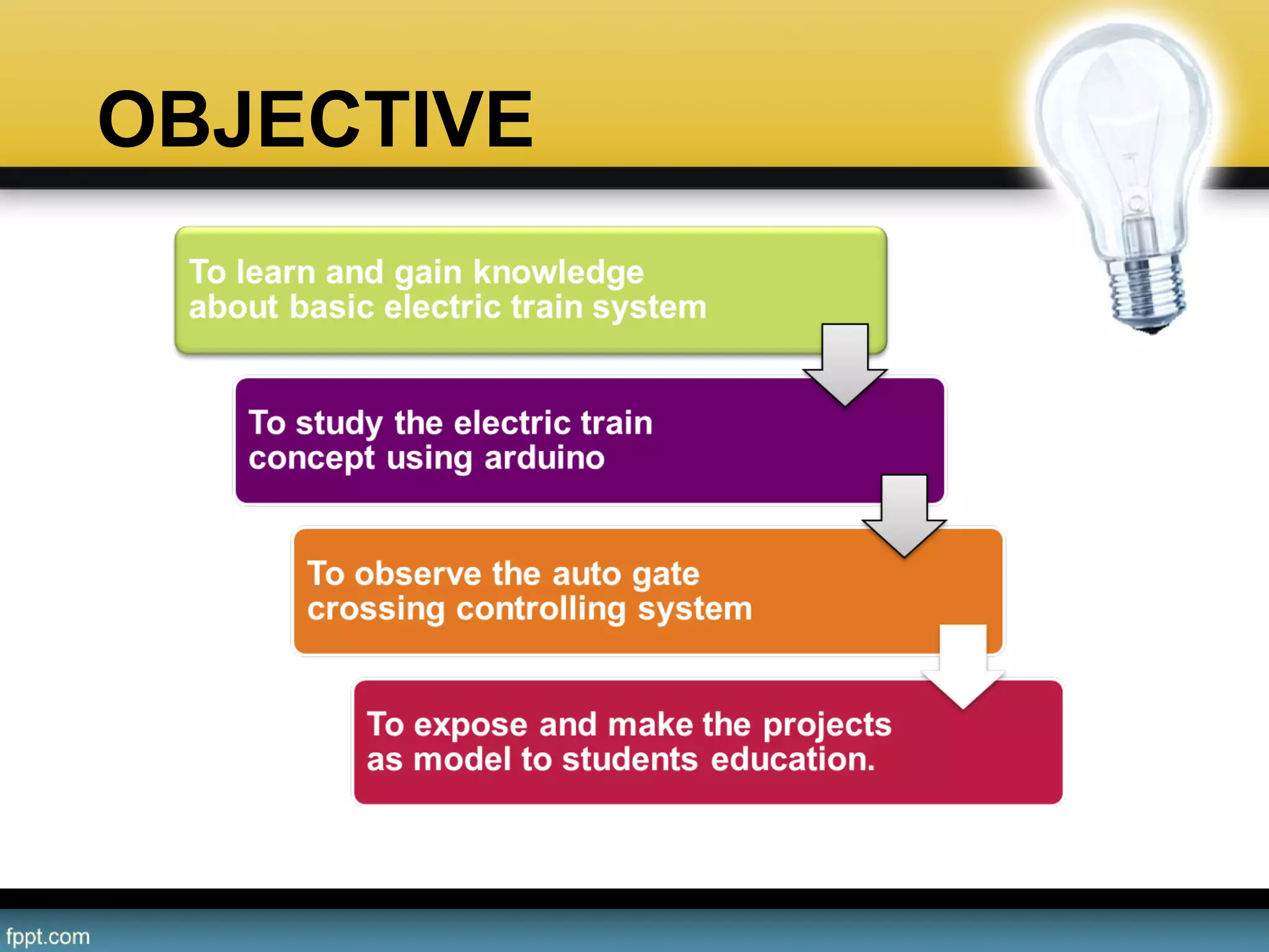
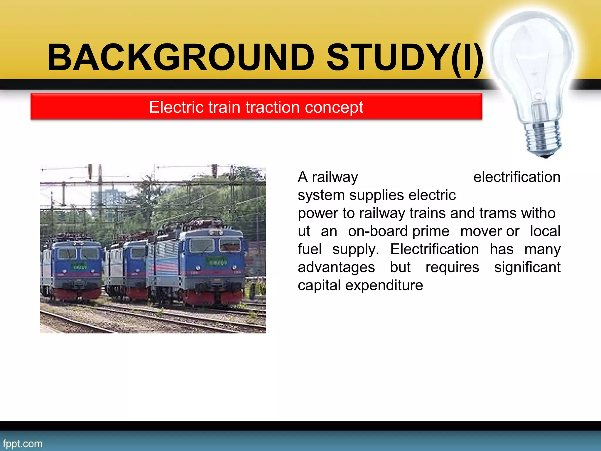
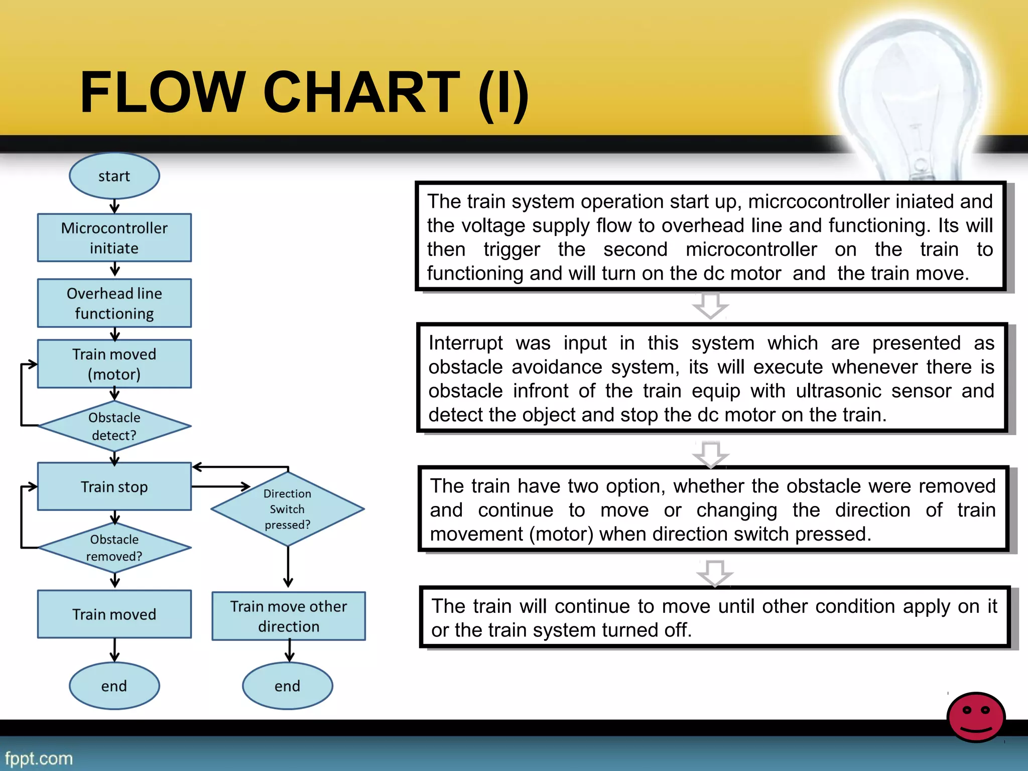
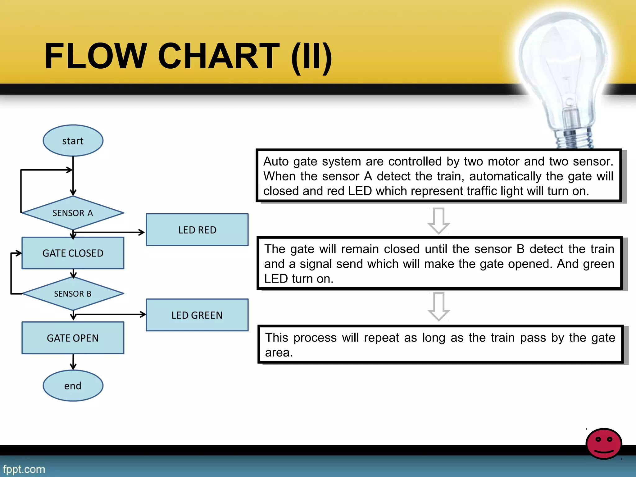
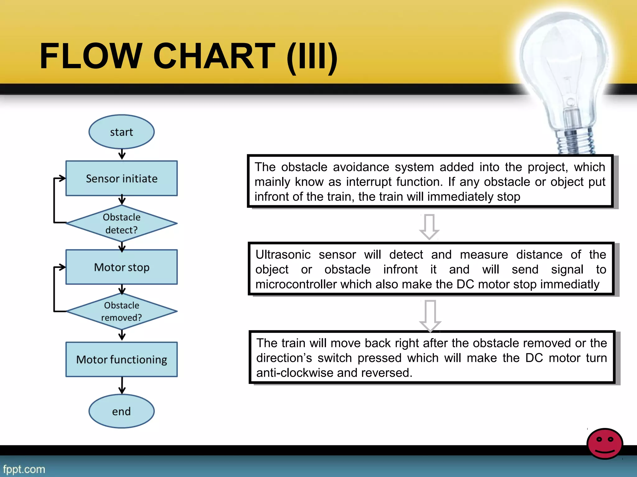
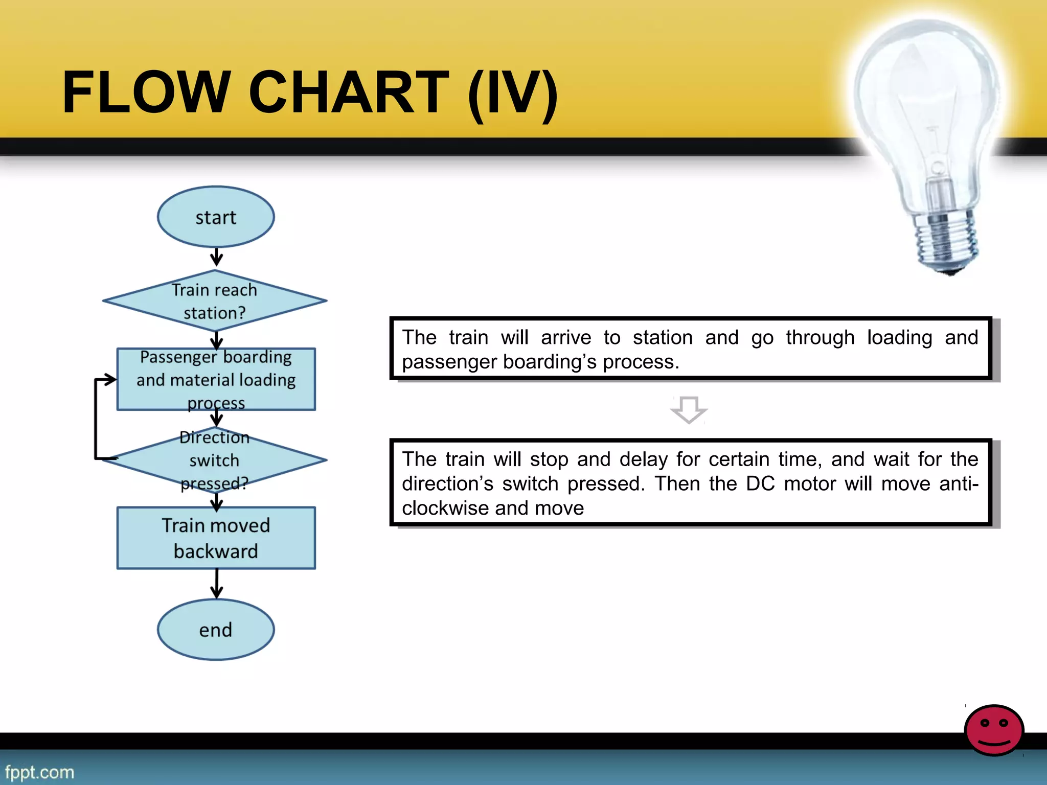
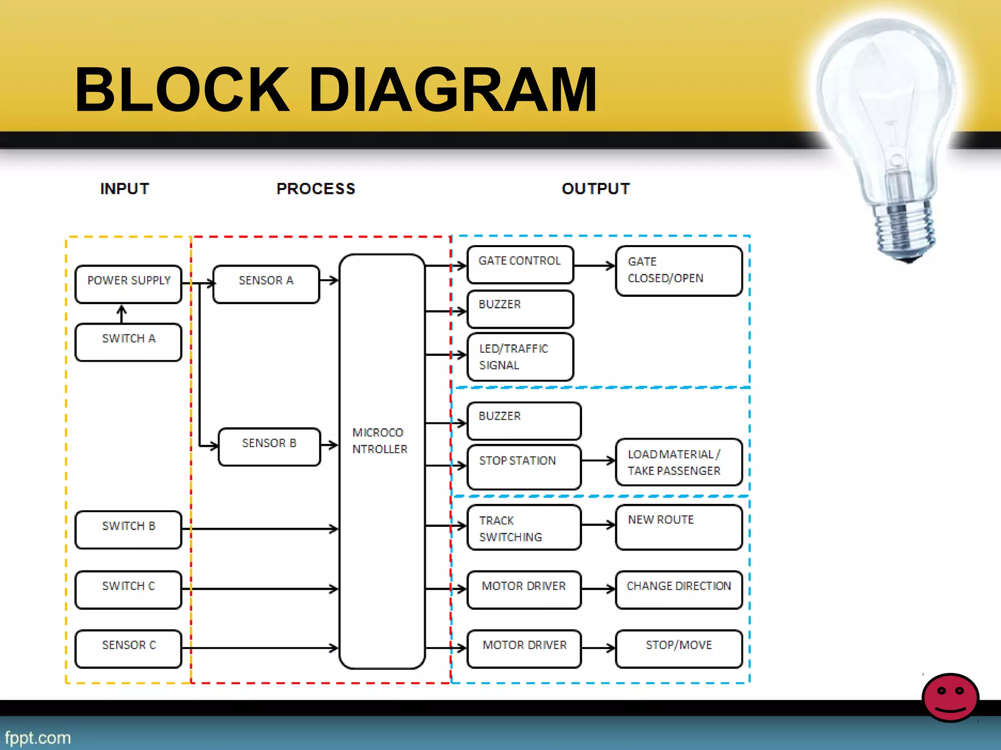
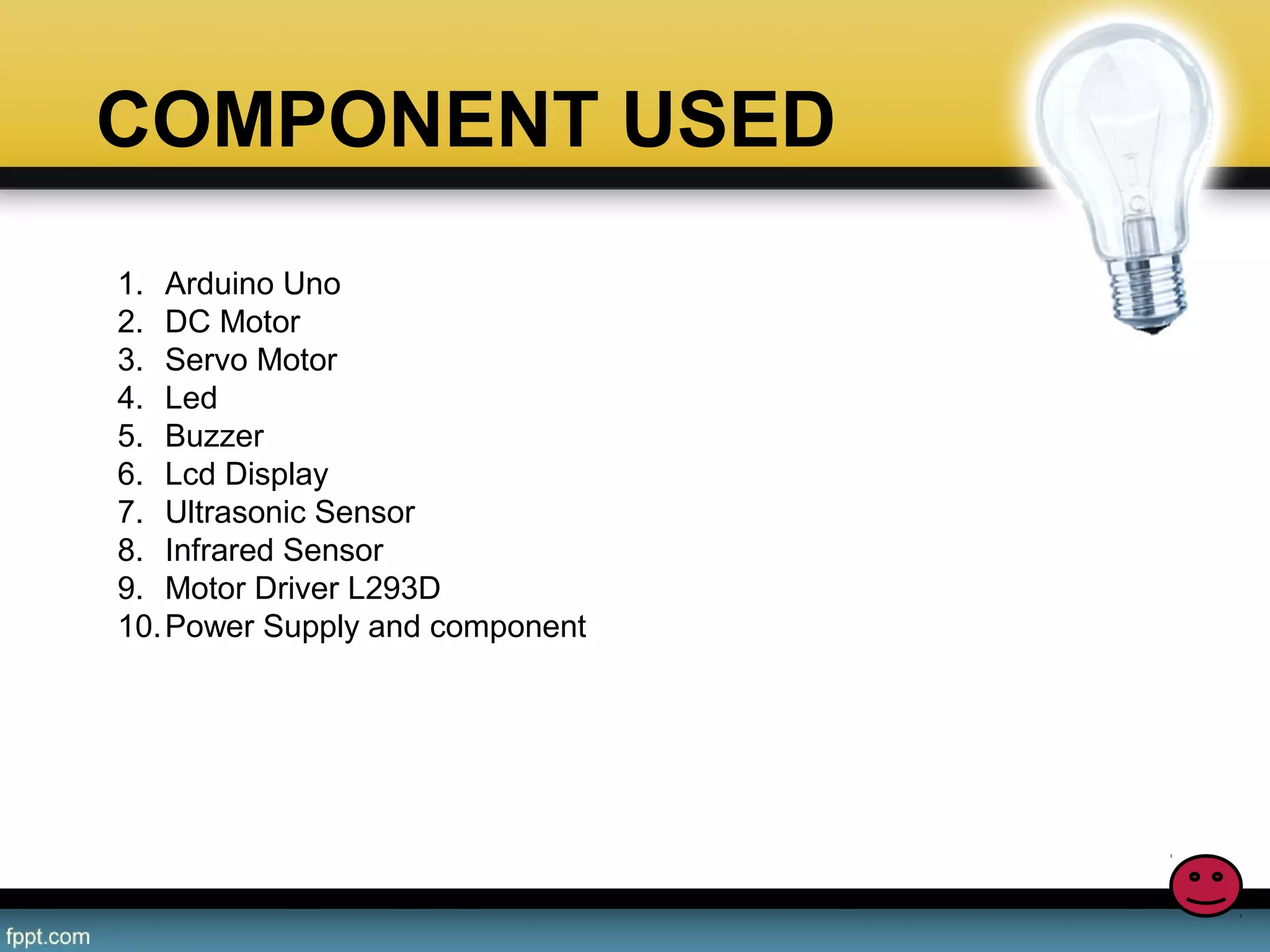
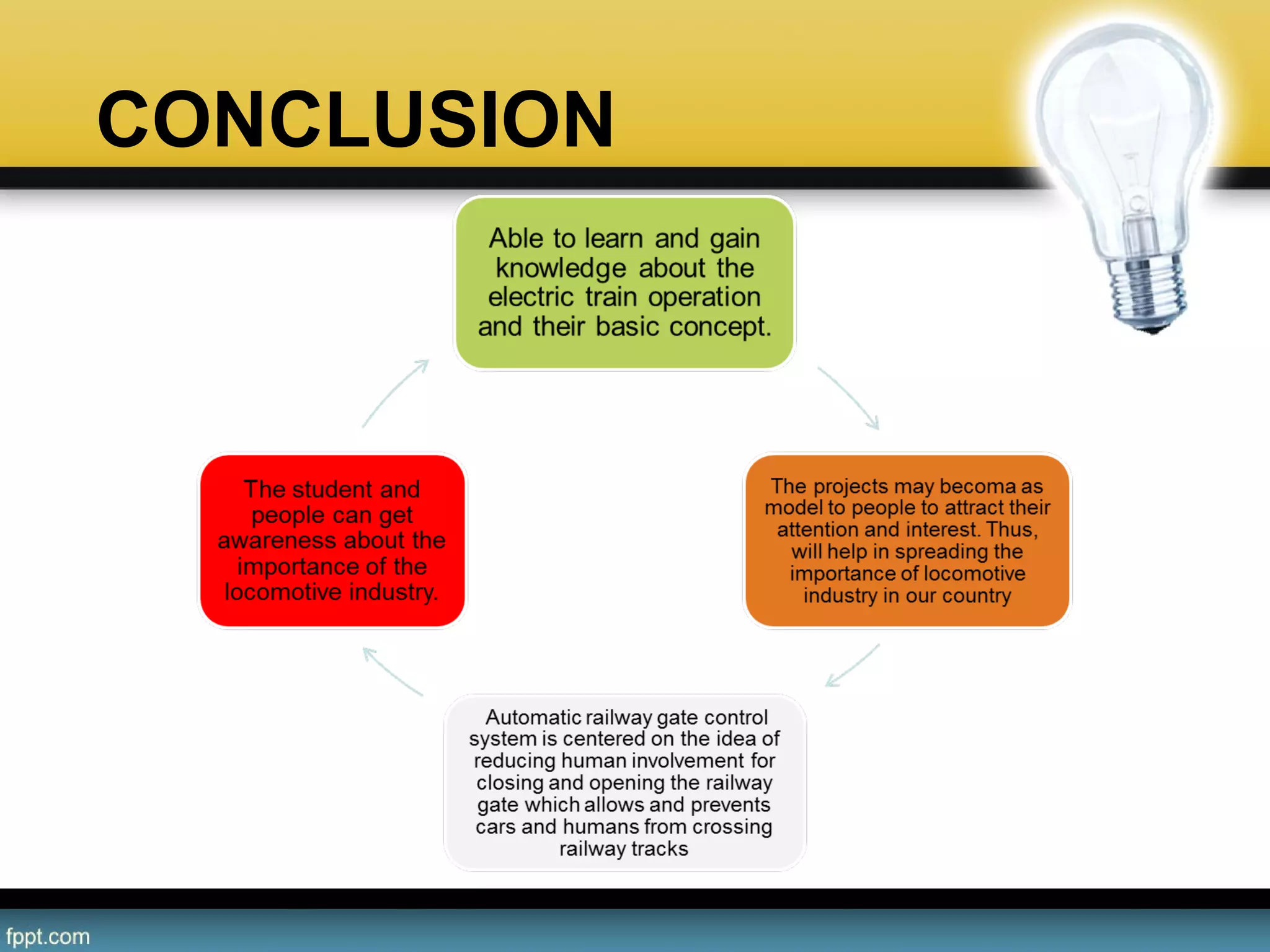
DEVELOPMENT OF ELECTRIC TRAIN
SYSTEM USING MICROCONTROLLER
NABIL HARITH BIN MOHD NAJIB
BET (HONS) in ELECTRONICS
SUPERVISED BY : MADAM AZLIZA
INTRODUCTION
The aim of the project designed is to learn and study about the
electric train system which include of train traction system, gate
controlling system, passenger & load material process, obstacle
avoidance operation and more.
The aim of the project designed is to learn and study about the
electric train system which include of train traction system, gate
controlling system, passenger & load material process, obstacle
avoidance operation and more.
The train will move, then gate sensor detected the train, and the gate
system will functioning, and its will stop at one or two station for
loading material and passenger boarding process, then when switch
clicked, the track will changed / switching and stop at last station.
Additional feature is obstacle avoidance operation
WHAT IS
IT ABOUT
WHAT IS
IT ABOUT
HOW
DOES IT
WORKS
HOW
DOES IT
WORKS
PROBLEM STATEMENT
• Malaysia rely too much to other’s country expertise on the
locomotive industry.
• We have less expertise or awareness of the locomotive inductry
• We spent a lot of money for the locomotive field
OBJECTIVE
BACKGROUND STUDY(I)
A railway electrification
system supplies electric
power to railway trains and trams witho
ut an on-board prime mover or local
fuel supply. Electrification has many
advantages but requires significant
capital expenditure
•Different systems are used for urban
and intercity areas; some electric
locomotives can switch to different
supply voltages to allow flexibility in
operation.
Electric train traction concept
BACKGROUND STUDY(I)
• A voltage will supply the electric
train through overhead line and
pantograph.
• The dc motor will work up and train
will started to movve.
• The dc motor also can be switch
direction when a button is clicked
Electric train traction concept
BACKGROUND STUDY(II)
• A level  crossing,  or grade  crossing,  is  an 
intersection  where  a railway  line crosses 
a road or path at  the  same  level,  as 
opposed to the railway line crossing over or 
under using a bridge or tunnel.
• Railroad  trains  have  a  much 
larger mass relative  to  their  braking 
capability,  and  thus  a  far  longer braking 
distance than  road  vehicles.  In  general, 
trains do not stop at level crossings but rely 
on  vehicles  and  pedestrians  to  clear  the 
tracks in advance.
Level Crossing (Auto gate system)
BACKGROUND STUDY(II)
• In  Reflective  Type  IR  Sensor,  the  IR 
transmitter  and  receiver  are  placed 
side  by  side.  When  there  is  no 
obstacle in front of the sensor, the IR 
rays transmitted by the IR Transmitter 
will travel undetected as there are no 
rays falling on the IR Receiver.
• If there is an obstacle in front of the IR 
Transmitter and Receiver pair, the IR 
Rays  gets  reflected  off  from  the 
surface  of  the  obstacle  and  are 
incident on the IR Receiver.
Level Crossing (Auto gate system)
BACKGROUND STUDY(II)
• EVERY minute, on average, at least one person dies in a train 
crash. Auto accidents also injure at least 10 million people each 
year, two or three million of them seriously. 
• The dc motor will stop when an
     obstacle is detected by ultrasonic
     sensor.
• After the obstacle removed
     the dc motor of the train is
     working and move.
Obstacle Avoidance
METHODOLOGY
FLOWCHART
BLOCK 
DIAGRAM
TECHNOLOGY
FLOW CHART (I)
The train system operation start up, micrcocontroller iniated and 
the voltage supply flow to overhead line and functioning. Its will 
then  trigger  the  second  microcontroller  on  the  train  to 
functioning and will turn on the dc motor  and  the train move.
The train system operation start up, micrcocontroller iniated and 
the voltage supply flow to overhead line and functioning. Its will 
then  trigger  the  second  microcontroller  on  the  train  to 
functioning and will turn on the dc motor  and  the train move.
Interrupt  was  input  in  this  system  which  are  presented  as 
obstacle avoidance system, its  will execute whenever there is 
obstacle  infront  of  the  train  equip  with  ultrasonic  sensor  and 
detect the object and stop the dc motor on the train.
Interrupt  was  input  in  this  system  which  are  presented  as 
obstacle  avoidance  system,  its  will execute whenever there is 
obstacle  infront  of  the  train  equip  with  ultrasonic  sensor  and 
detect the object and stop the dc motor on the train.
The train have two option, whether the obstacle were removed 
and  continue  to  move  or  changing  the  direction  of  train 
movement (motor) when direction switch pressed.
The train have two option, whether the obstacle were removed 
and  continue  to  move  or  changing  the  direction  of  train 
movement (motor) when direction switch pressed.
The train will continue to move until other condition apply on it 
or the train system turned off.
The train will continue to move until other condition apply on it 
or the train system turned off.
FLOW CHART (II)
Auto gate system are controlled by two motor and two sensor. 
When the sensor A detect the train, automatically the gate will 
closed and red LED which represent traffic light will turn on.
Auto gate system are controlled by two motor and two sensor. 
When the sensor A detect the train, automatically the gate will 
closed and red LED which represent traffic light will turn on.
The gate will remain closed until the sensor B detect the train 
and a signal send which will make the gate opened. And green 
LED turn on.
The gate will remain closed until the sensor B detect the train 
and a signal send which will make the gate opened. And green 
LED turn on.
This process will repeat as long as the train pass by the gate 
area.
This process will repeat as long as the train pass by the gate 
area.
FLOW CHART (III)
The obstacle avoidance system added into the project, which
mainly know as interrupt function. If any obstacle or object put
infront of the train, the train will immediately stop
The obstacle avoidance system added into the project, which
mainly know as interrupt function. If any obstacle or object put
infront of the train, the train will immediately stop
Ultrasonic sensor will detect and measure distance of the
object or obstacle infront it and will send signal to
microcontroller which also make the DC motor stop immediatly
Ultrasonic sensor will detect and measure distance of the
object or obstacle infront it and will send signal to
microcontroller which also make the DC motor stop immediatly
The train will move back right after the obstacle removed or the
direction’s switch pressed which will make the DC motor turn
anti-clockwise and reversed.
The train will move back right after the obstacle removed or the
direction’s switch pressed which will make the DC motor turn
anti-clockwise and reversed.
FLOW CHART (IV)
The train will arrive to station and go through loading and
passenger boarding’s process.
The train will arrive to station and go through loading and
passenger boarding’s process.
The train will stop and delay for certain time, and wait for the
direction’s switch pressed. Then the DC motor will move anti-
clockwise and move
The train will stop and delay for certain time, and wait for the
direction’s switch pressed. Then the DC motor will move anti-
clockwise and move
BLOCK DIAGRAM
COMPONENT USED
DC MOTOR
ULTRA SONIC SENSOR
IR SENSOR
LCD DISPLAY
ARDUINO MICROCONTROLLER
RELAY
WIRE
BUZZER
LED
1. Arduino Uno
2. DC Motor
3. Servo Motor
4. Led
5. Buzzer
6. Lcd Display
7. Ultrasonic Sensor
8. Infrared Sensor
9. Motor Driver L293D
10.Power Supply and component
SOFTWARE USED
ARDUINO
SOFTWARE
PROTEUS
DESIGN SUITE
EXPECTED RESULT
PROJECT MILESTONE
• FYP1
Task Descriptions W1 W2 W3 W4 W5 W6 W7 W8 W9 W10 W11 W12 W13 W14
FIND PROJECT
SUPERVISOR
/ /  /                     
PROJECT TITLE
SELECTION
  /  /  /                  
RESEARCH    / /  / /  / / / / / / / / /
PREPARE LOGBOOK
ONLINE
  / / / / / / / / / / / / /
PROPOSAL
PREPARATION
      / / / / / / / / /  
FYP1 PRESENTATION                       / 
FINAL PROPOSAL AND
SUBMISSION
                        /
CONCLUSION
REFERENCE
1. Improving Railway Safety with Obstacle Detection and Tracking 
System using GPS-GSM Model by Nisha S.Punekar 1 , Archana A. 
Raut
2. Wikipedia - https://en.wikipedia.org/wiki/Level_crossing
3. Wikipedia - https://en.wikipedia.org/wiki/Railway_electric_traction
4. Instructables - http://www.instructables.com/id/Automatic-Railway-
Crossing-Using-Arduino/
5. Ardutrain blog - http://ardutrain.blogspot.my/

Nabil slide fyp1 new