Download to read offline
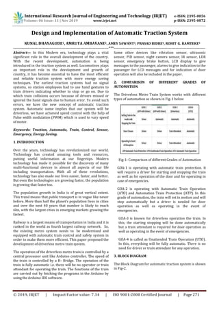
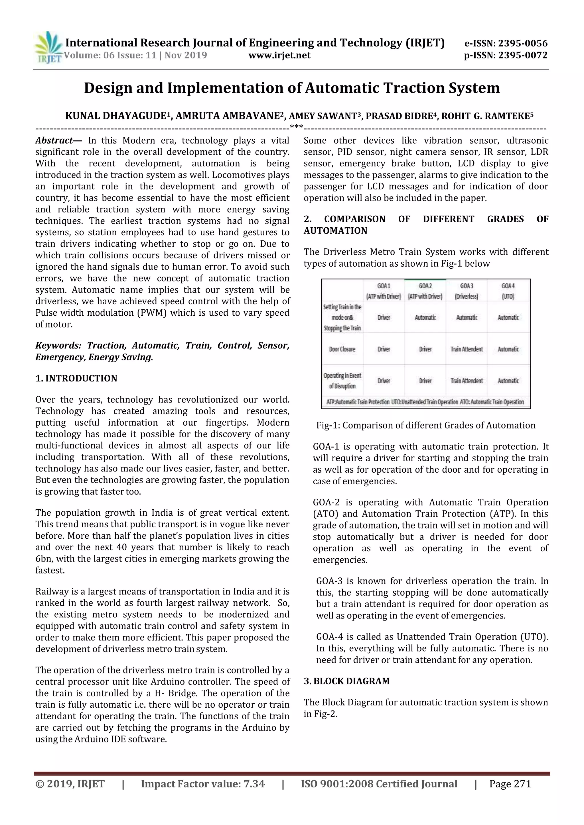
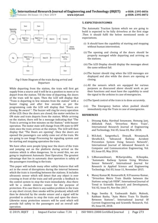

The document proposes the design and implementation of an automatic traction system for trains. It discusses how earlier traction systems relied on hand signals which led to accidents from human error. The proposed system aims to make trains driverless using sensors and automatic control of speed and doors. It describes different grades of automation from GOA-1 requiring a driver to GOA-4 being fully unattended. The system would use a Raspberry Pi and Arduino controller along with sensors like ultrasonic, smoke and vibration sensors. It provides block diagrams of the system and components. It also outlines the expected outcomes like starting, stopping and door operation without human intervention along with safety features to stop the train if sensors detect issues.