Downloaded 160 times


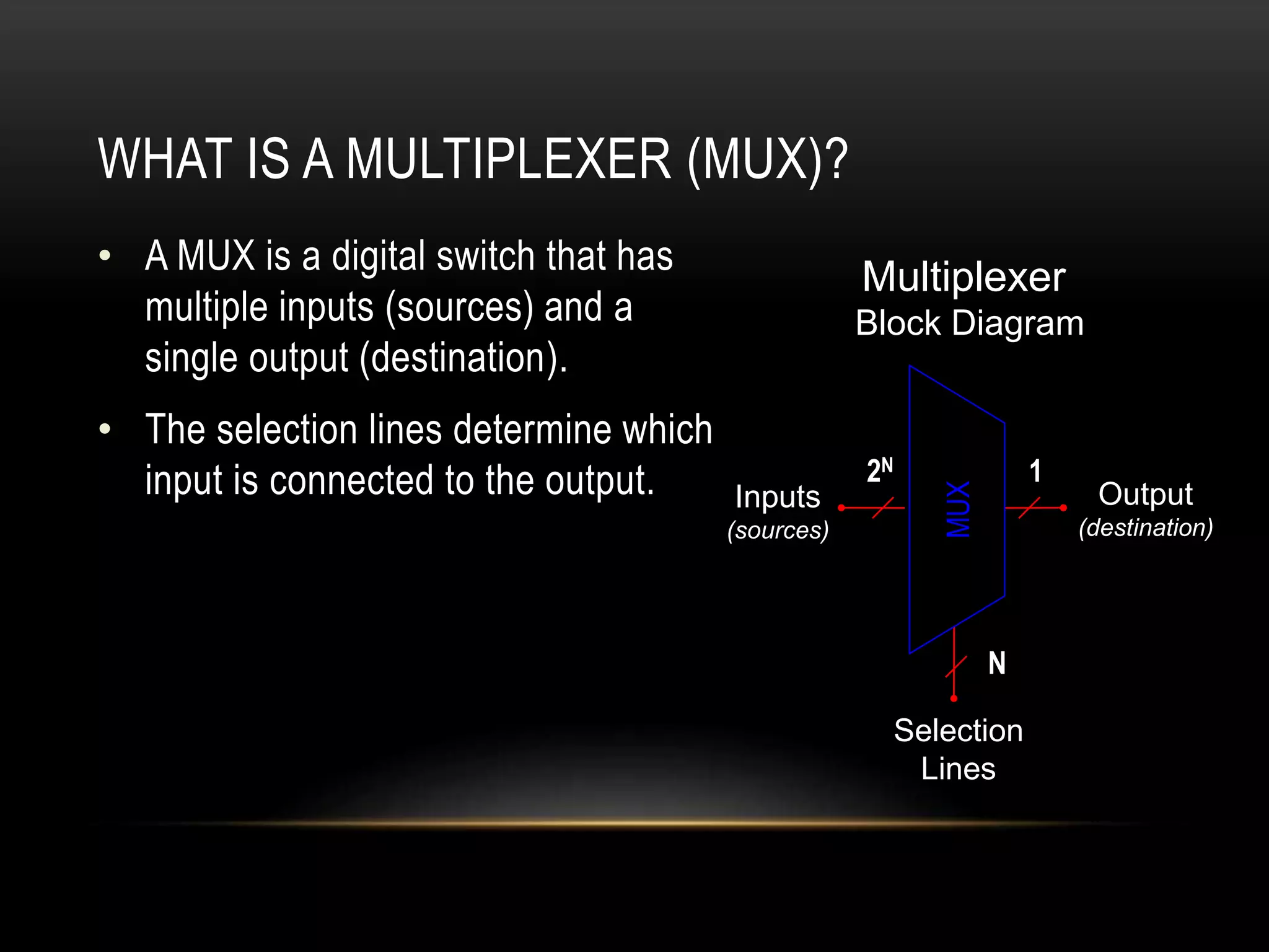
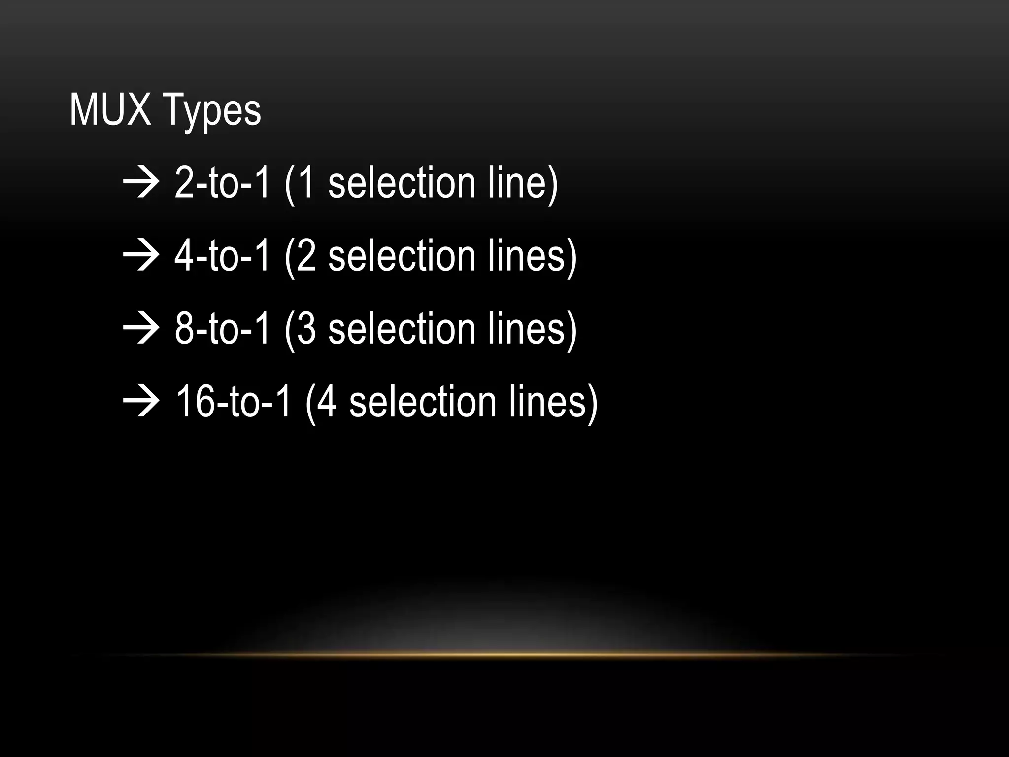
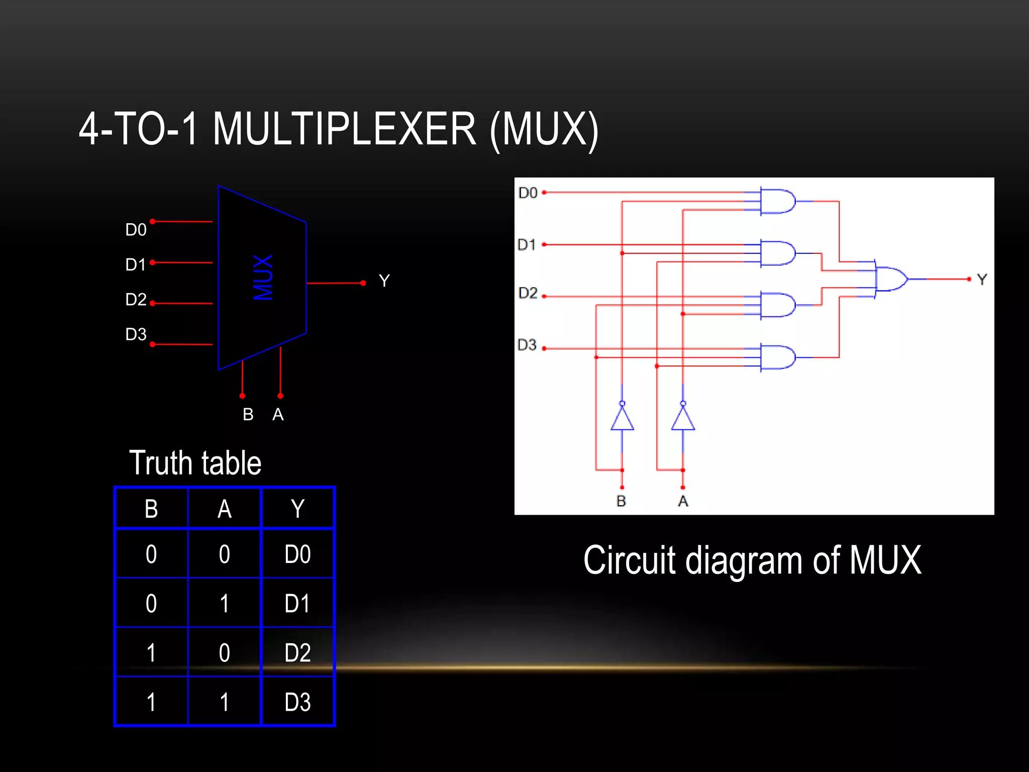
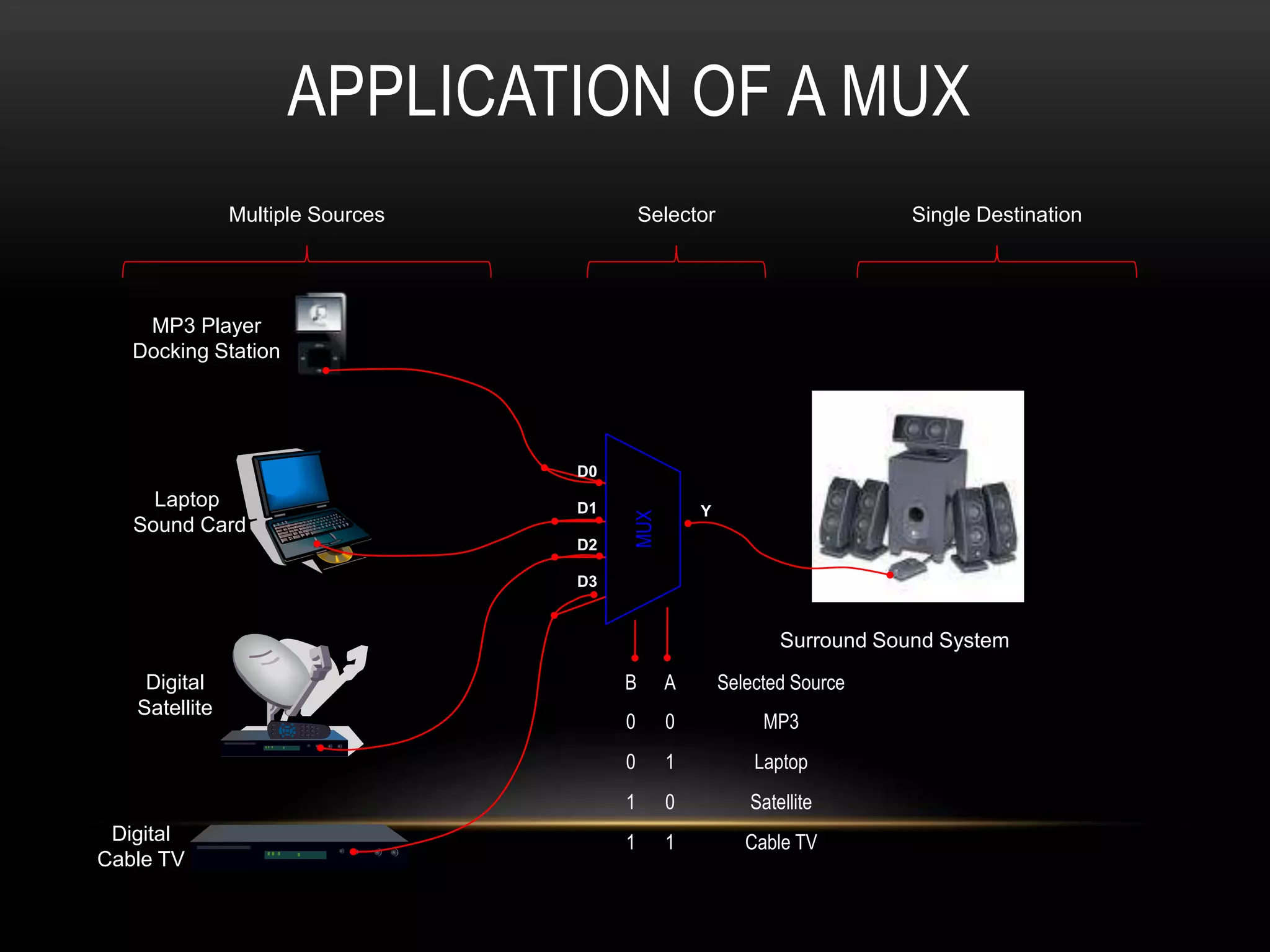
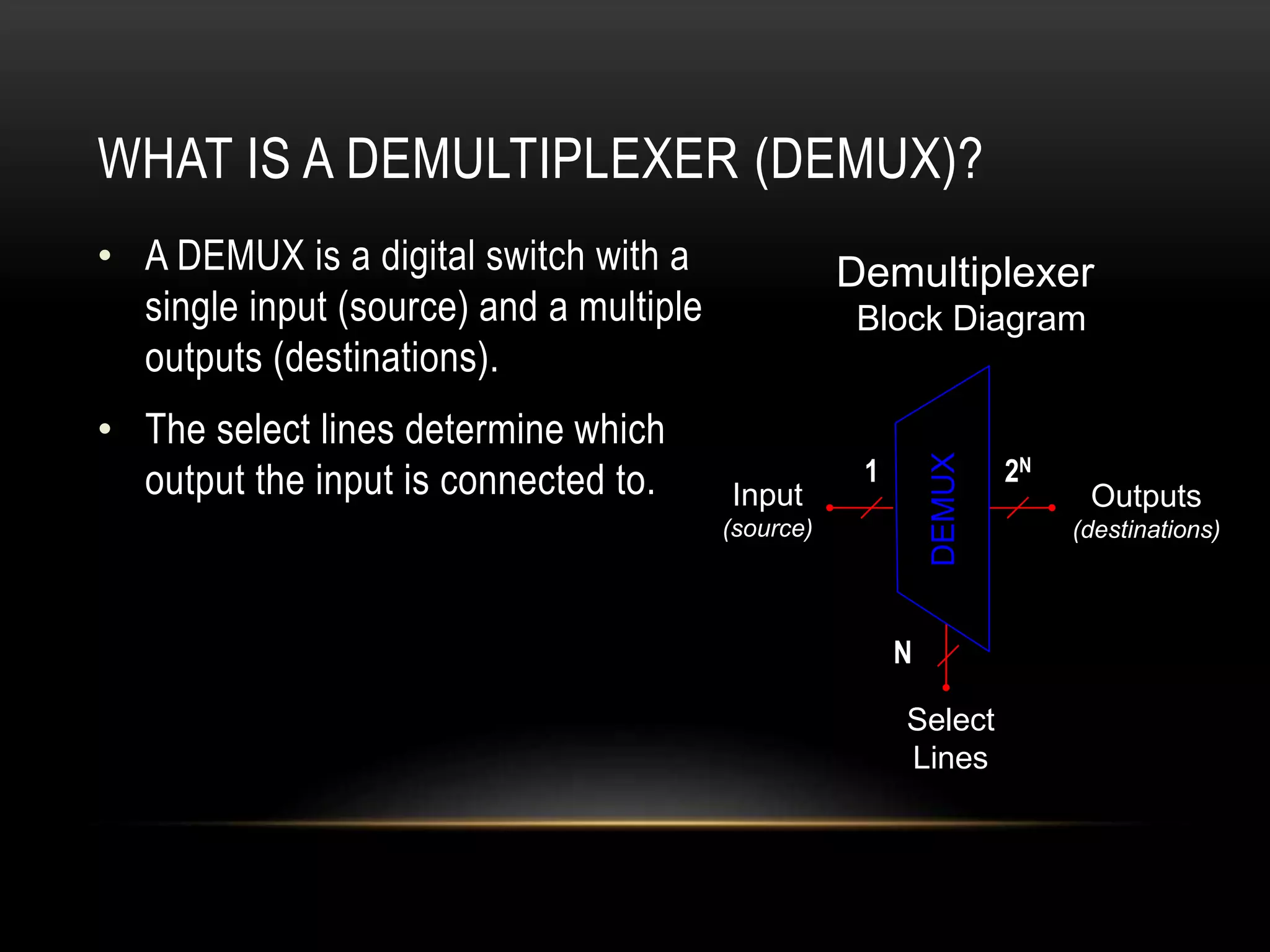
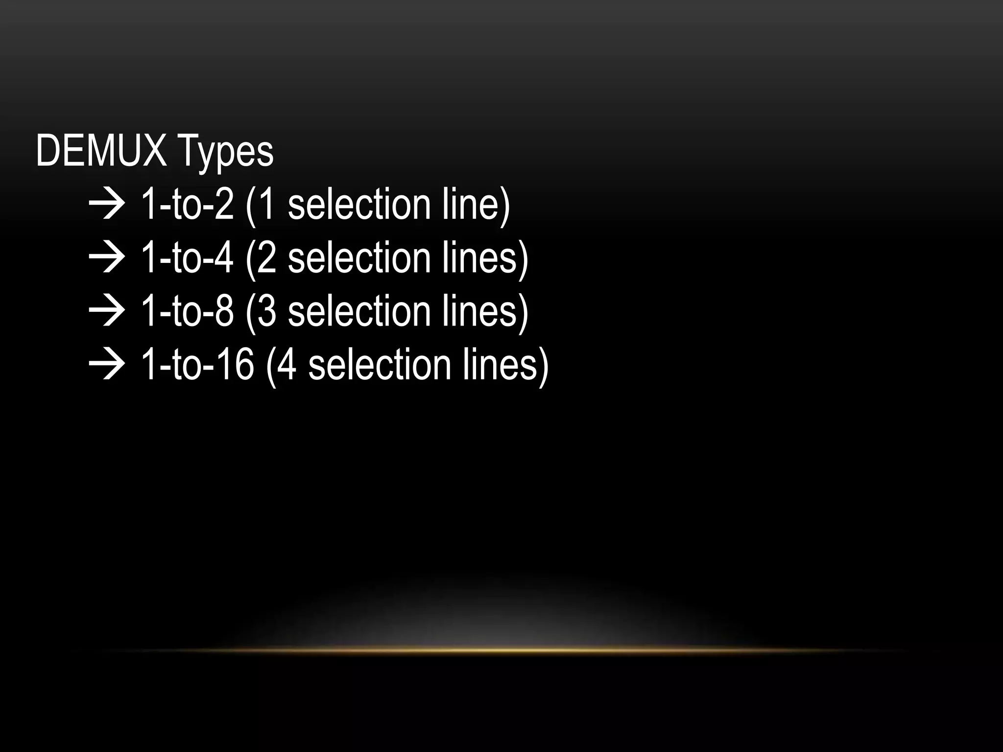
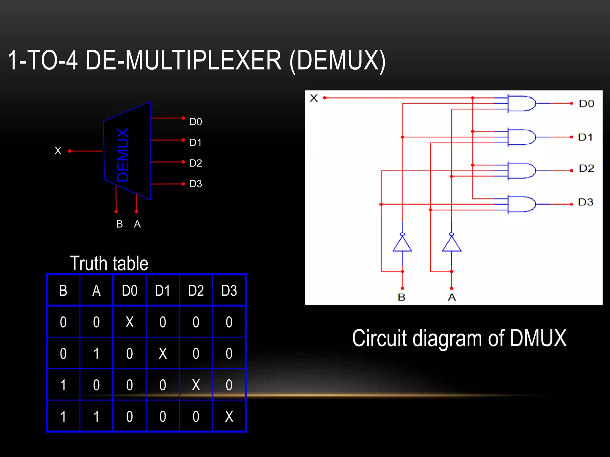
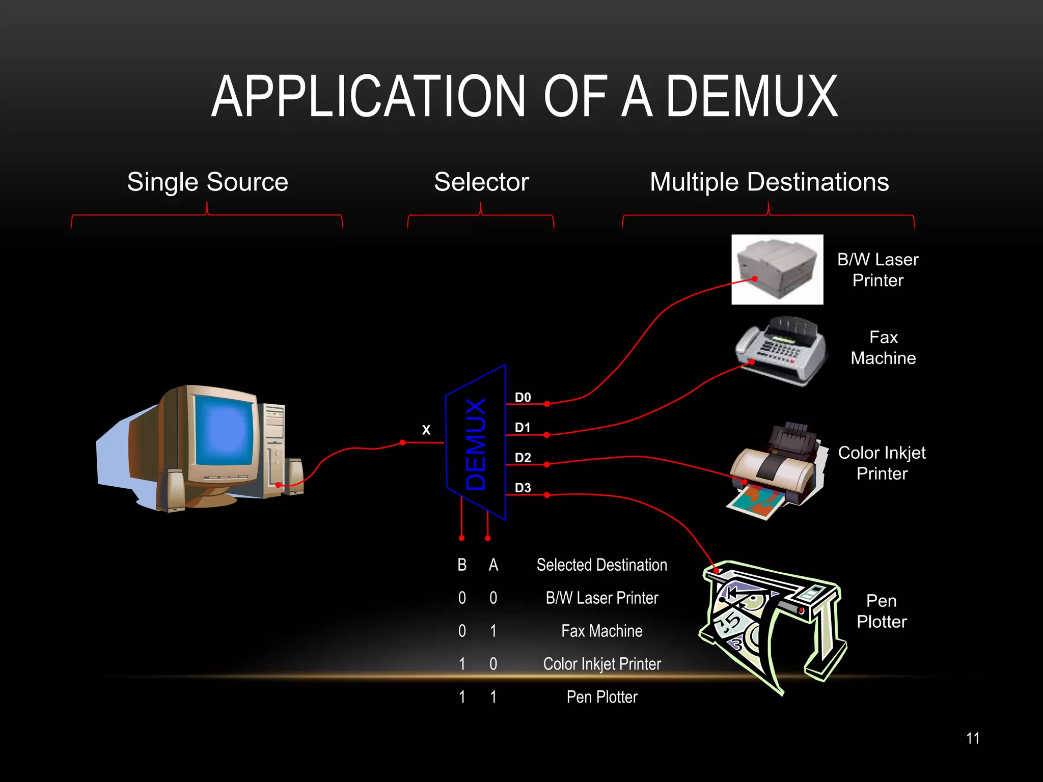


The presentation covers the concepts of multiplexers (mux) and demultiplexers (demux), detailing their definitions, types, and applications. A multiplexer allows multiple inputs to connect to a single output, while a demultiplexer connects a single input to multiple outputs. Specific types, such as 4-to-1 mux and 1-to-8 demux, are presented along with their respective circuit diagrams and truth tables.


