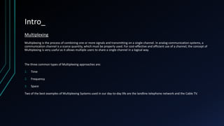
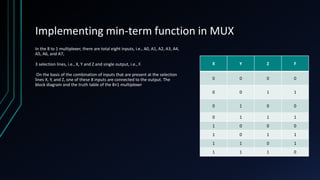
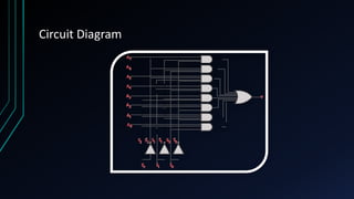
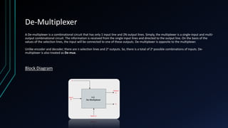
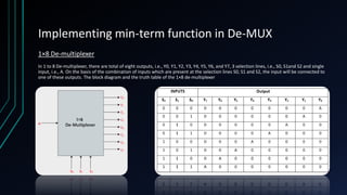
SlideShare a Scribd company logo
1 of 10
MULTIPLEXER(MUX)
A P R ES E N TAT I O N A B O U T M U LT I P L E X I N G
Mehedi Hasan
CSE, DIU
(b-74)
Index
• Introduction
• A Closer look at Multiplexer
• Implementing minterm function in MUX
• Circuit Diagram
• De-MUX
Intro_
Multiplexing
Multiplexing is the process of combining one or more signals and transmitting on a single channel. In analog communication systems, a
communication channel is a scarce quantity, which must be properly used. For cost-effective and efficient use of a channel, the concept of
Multiplexing is very useful as it allows multiple users to share a single channel in a logical way.
The three common types of Multiplexing approaches are:
1. Time
2. Frequency
3. Space
Two of the best examples of Multiplexing Systems used in our day-to-day life are the landline telephone network and the Cable TV.
A Closer look at Multiplexer
What is Multiplexer
A Digital Multiplexer is a combinational circuit that select a Binary information from one of many input lines and more than one select line.
The multiplexer or MUX is a digital switch, also called as data selector. The basic idea of multiplexing is shown in figure below in which data
from several sources are routed to the single output line when the enable switch is ON. This is why, multiplexers are also called as ‘many to
one’ combinational circuits.
If there are m selection lines, then the number of possible input lines is 2m. Alternatively, we can say that if the number of input lines is
equal to 2m, then m selection lines are required to select one of n (consider 2m = n) input lines.
This type of multiplexer is referred to as 2n × 1 multiplexer or 2n-to-1 multiplexer. For example, if the number of input lines is 4, then two
select lines are required. Similarly, to select one of 8 input lines, three select lines are required.
Implementing min-term function in MUX
Boolean function implementation
Any n-variable logic function can be implemented using a smaller 2n-1-to-1 multiplexer and a single inverter.
D.Q. Implement the function F(X,Y,Z) = S(1,3,5,6) using an 8-to-1 mux.
Connect the input variables X, Y, Z to mux select lines. Mux data input lines 1, 3, 5, 6 that correspond to the function min-terms are
connected to 1. The remaining mux data input lines 0, 2, 4, 7 are connected to 0.
Implementing min-term function in MUX
X Y Z F
0 0 0 0
0 0 1 1
0 1 0 0
0 1 1 1
1 0 0 0
1 0 1 1
1 1 0 1
1 1 1 0
In the 8 to 1 multiplexer, there are total eight inputs, i.e., A0, A1, A2, A3, A4,
A5, A6, and A7,
3 selection lines, i.e., X, Y and Z and single output, i.e., F.
On the basis of the combination of inputs that are present at the selection
lines X, Y, and Z, one of these 8 inputs are connected to the output. The
block diagram and the truth table of the 8×1 multiplexer
Circuit Diagram
De-Multiplexer
A De-multiplexer is a combinational circuit that has only 1 input line and 2N output lines. Simply, the multiplexer is a single-input and multi-
output combinational circuit. The information is received from the single input lines and directed to the output line. On the basis of the
values of the selection lines, the input will be connected to one of these outputs. De-multiplexer is opposite to the multiplexer.
Unlike encoder and decoder, there are n selection lines and 2n outputs. So, there is a total of 2n possible combinations of inputs. De-
multiplexer is also treated as De-mux.
Block Diagram
Implementing min-term function in De-MUX
1×8 De-multiplexer
In 1 to 8 De-multiplexer, there are total of eight outputs, i.e., Y0, Y1, Y2, Y3, Y4, Y5, Y6, and Y7, 3 selection lines, i.e., S0, S1and S2 and single
input, i.e., A. On the basis of the combination of inputs which are present at the selection lines S0, S1 and S2, the input will be connected to
one of these outputs. The block diagram and the truth table of the 1×8 de-multiplexer
Thank
You
EveryOne

More Related Content

Similar to MULTIPLEXER Circuit in Digital system/electronics/logic

MULTIPLEXER AND DEMULTIPLXERwjdwdwdd.ppt
MULTIPLEXER AND DEMULTIPLXERwjdwdwdd.pptMULTIPLEXER AND DEMULTIPLXERwjdwdwdd.ppt
MULTIPLEXER AND DEMULTIPLXERwjdwdwdd.ppt
HusnainNaqvi2
 
Multiplexer and Demultiplexer.pdf
Multiplexer and Demultiplexer.pdfMultiplexer and Demultiplexer.pdf
Multiplexer and Demultiplexer.pdf
sudarmani5694
 
MIMO system (potential candidate for 4G system)
MIMO system (potential candidate for 4G system)MIMO system (potential candidate for 4G system)
MIMO system (potential candidate for 4G system)
Virak Sou
 

Similar to MULTIPLEXER Circuit in Digital system/electronics/logic (20)

week 6 -Multiplexer & Demultiplexer.ppt
week 6 -Multiplexer & Demultiplexer.pptweek 6 -Multiplexer & Demultiplexer.ppt
week 6 -Multiplexer & Demultiplexer.ppt
 
Performance Analysis of Various Symbol Detection Techniques in Wireless MIMO ...
Performance Analysis of Various Symbol Detection Techniques in Wireless MIMO ...Performance Analysis of Various Symbol Detection Techniques in Wireless MIMO ...
Performance Analysis of Various Symbol Detection Techniques in Wireless MIMO ...
 
Performance Analysis of Various Symbol Detection Techniques in Wireless MIMO ...
Performance Analysis of Various Symbol Detection Techniques in Wireless MIMO ...Performance Analysis of Various Symbol Detection Techniques in Wireless MIMO ...
Performance Analysis of Various Symbol Detection Techniques in Wireless MIMO ...
 
18 15993 31427-1-sm(edit)nn
18 15993 31427-1-sm(edit)nn18 15993 31427-1-sm(edit)nn
18 15993 31427-1-sm(edit)nn
 
MULTIPLEXER AND DEMULTIPLXERwjdwdwdd.ppt
MULTIPLEXER AND DEMULTIPLXERwjdwdwdd.pptMULTIPLEXER AND DEMULTIPLXERwjdwdwdd.ppt
MULTIPLEXER AND DEMULTIPLXERwjdwdwdd.ppt
 
Multiplexer and De multiplexers.docx
Multiplexer and De multiplexers.docxMultiplexer and De multiplexers.docx
Multiplexer and De multiplexers.docx
 
Performance Comparison of Modified Variable Step Size Leaky LMS Algorithm for...
Performance Comparison of Modified Variable Step Size Leaky LMS Algorithm for...Performance Comparison of Modified Variable Step Size Leaky LMS Algorithm for...
Performance Comparison of Modified Variable Step Size Leaky LMS Algorithm for...
 
Multiuser MIMO Gaussian Channels: Capacity Region and Duality
Multiuser MIMO Gaussian Channels: Capacity Region and DualityMultiuser MIMO Gaussian Channels: Capacity Region and Duality
Multiuser MIMO Gaussian Channels: Capacity Region and Duality
 
Performance evaluation with a
Performance evaluation with aPerformance evaluation with a
Performance evaluation with a
 
MIMO Channel Estimation Using the LS and MMSE Algorithm
MIMO Channel Estimation Using the LS and MMSE AlgorithmMIMO Channel Estimation Using the LS and MMSE Algorithm
MIMO Channel Estimation Using the LS and MMSE Algorithm
 
BER Performance of MU-MIMO System using Dirty Paper Coding
BER Performance of MU-MIMO System using Dirty Paper CodingBER Performance of MU-MIMO System using Dirty Paper Coding
BER Performance of MU-MIMO System using Dirty Paper Coding
 
paperVTCFall2009
paperVTCFall2009paperVTCFall2009
paperVTCFall2009
 
Hardware efficient singular value decomposition in mimo ofdm system
Hardware efficient singular value decomposition in mimo ofdm systemHardware efficient singular value decomposition in mimo ofdm system
Hardware efficient singular value decomposition in mimo ofdm system
 
Peak to–average power ratio reduction of ofdm siganls
Peak to–average power ratio reduction of ofdm siganlsPeak to–average power ratio reduction of ofdm siganls
Peak to–average power ratio reduction of ofdm siganls
 
Peak to-average power ratio reduction of ofdm siganls
Peak to-average power ratio reduction of ofdm siganlsPeak to-average power ratio reduction of ofdm siganls
Peak to-average power ratio reduction of ofdm siganls
 
Computationally Efficient Multi-Antenna Techniques for Multi-User Two-Way Wire...
Computationally Efficient Multi-Antenna Techniques for Multi-User Two-Way Wire...Computationally Efficient Multi-Antenna Techniques for Multi-User Two-Way Wire...
Computationally Efficient Multi-Antenna Techniques for Multi-User Two-Way Wire...
 
Multiplexer and Demultiplexer.pdf
Multiplexer and Demultiplexer.pdfMultiplexer and Demultiplexer.pdf
Multiplexer and Demultiplexer.pdf
 
MIMO system (potential candidate for 4G system)
MIMO system (potential candidate for 4G system)MIMO system (potential candidate for 4G system)
MIMO system (potential candidate for 4G system)
 
Mimo
MimoMimo
Mimo
 

Recently uploaded

1_Introduction + EAM Vocabulary + how to navigate in EAM.pdf
1_Introduction + EAM Vocabulary + how to navigate in EAM.pdf1_Introduction + EAM Vocabulary + how to navigate in EAM.pdf
1_Introduction + EAM Vocabulary + how to navigate in EAM.pdf
AldoGarca30
 
Hospital management system project report.pdf
Hospital management system project report.pdfHospital management system project report.pdf
Hospital management system project report.pdf
Kamal Acharya
 
Standard vs Custom Battery Packs - Decoding the Power Play
Standard vs Custom Battery Packs - Decoding the Power PlayStandard vs Custom Battery Packs - Decoding the Power Play
Standard vs Custom Battery Packs - Decoding the Power Play
Epec Engineered Technologies
 
Call Girls in South Ex (delhi) call me [🔝9953056974🔝] escort service 24X7
Call Girls in South Ex (delhi) call me [🔝9953056974🔝] escort service 24X7Call Girls in South Ex (delhi) call me [🔝9953056974🔝] escort service 24X7
Call Girls in South Ex (delhi) call me [🔝9953056974🔝] escort service 24X7
9953056974 Low Rate Call Girls In Saket, Delhi NCR
 
"Lesotho Leaps Forward: A Chronicle of Transformative Developments"
"Lesotho Leaps Forward: A Chronicle of Transformative Developments""Lesotho Leaps Forward: A Chronicle of Transformative Developments"
"Lesotho Leaps Forward: A Chronicle of Transformative Developments"
mphochane1998
 

Recently uploaded (20)

1_Introduction + EAM Vocabulary + how to navigate in EAM.pdf
1_Introduction + EAM Vocabulary + how to navigate in EAM.pdf1_Introduction + EAM Vocabulary + how to navigate in EAM.pdf
1_Introduction + EAM Vocabulary + how to navigate in EAM.pdf
 
GEAR TRAIN- BASIC CONCEPTS AND WORKING PRINCIPLE
GEAR TRAIN- BASIC CONCEPTS AND WORKING PRINCIPLEGEAR TRAIN- BASIC CONCEPTS AND WORKING PRINCIPLE
GEAR TRAIN- BASIC CONCEPTS AND WORKING PRINCIPLE
 
Introduction to Serverless with AWS Lambda
Introduction to Serverless with AWS LambdaIntroduction to Serverless with AWS Lambda
Introduction to Serverless with AWS Lambda
 
Tamil Call Girls Bhayandar WhatsApp +91-9930687706, Best Service
Tamil Call Girls Bhayandar WhatsApp +91-9930687706, Best ServiceTamil Call Girls Bhayandar WhatsApp +91-9930687706, Best Service
Tamil Call Girls Bhayandar WhatsApp +91-9930687706, Best Service
 
S1S2 B.Arch MGU - HOA1&2 Module 3 -Temple Architecture of Kerala.pptx
S1S2 B.Arch MGU - HOA1&2 Module 3 -Temple Architecture of Kerala.pptxS1S2 B.Arch MGU - HOA1&2 Module 3 -Temple Architecture of Kerala.pptx
S1S2 B.Arch MGU - HOA1&2 Module 3 -Temple Architecture of Kerala.pptx
 
Hospital management system project report.pdf
Hospital management system project report.pdfHospital management system project report.pdf
Hospital management system project report.pdf
 
Standard vs Custom Battery Packs - Decoding the Power Play
Standard vs Custom Battery Packs - Decoding the Power PlayStandard vs Custom Battery Packs - Decoding the Power Play
Standard vs Custom Battery Packs - Decoding the Power Play
 
Work-Permit-Receiver-in-Saudi-Aramco.pptx
Work-Permit-Receiver-in-Saudi-Aramco.pptxWork-Permit-Receiver-in-Saudi-Aramco.pptx
Work-Permit-Receiver-in-Saudi-Aramco.pptx
 
NO1 Top No1 Amil Baba In Azad Kashmir, Kashmir Black Magic Specialist Expert ...
NO1 Top No1 Amil Baba In Azad Kashmir, Kashmir Black Magic Specialist Expert ...NO1 Top No1 Amil Baba In Azad Kashmir, Kashmir Black Magic Specialist Expert ...
NO1 Top No1 Amil Baba In Azad Kashmir, Kashmir Black Magic Specialist Expert ...
 
Call Girls in South Ex (delhi) call me [🔝9953056974🔝] escort service 24X7
Call Girls in South Ex (delhi) call me [🔝9953056974🔝] escort service 24X7Call Girls in South Ex (delhi) call me [🔝9953056974🔝] escort service 24X7
Call Girls in South Ex (delhi) call me [🔝9953056974🔝] escort service 24X7
 
Thermal Engineering Unit - I & II . ppt
Thermal Engineering  Unit - I & II . pptThermal Engineering  Unit - I & II . ppt
Thermal Engineering Unit - I & II . ppt
 
A Study of Urban Area Plan for Pabna Municipality
A Study of Urban Area Plan for Pabna MunicipalityA Study of Urban Area Plan for Pabna Municipality
A Study of Urban Area Plan for Pabna Municipality
 
Online food ordering system project report.pdf
Online food ordering system project report.pdfOnline food ordering system project report.pdf
Online food ordering system project report.pdf
 
Generative AI or GenAI technology based PPT
Generative AI or GenAI technology based PPTGenerative AI or GenAI technology based PPT
Generative AI or GenAI technology based PPT
 
Computer Lecture 01.pptxIntroduction to Computers
Computer Lecture 01.pptxIntroduction to ComputersComputer Lecture 01.pptxIntroduction to Computers
Computer Lecture 01.pptxIntroduction to Computers
 
Unleashing the Power of the SORA AI lastest leap
Unleashing the Power of the SORA AI lastest leapUnleashing the Power of the SORA AI lastest leap
Unleashing the Power of the SORA AI lastest leap
 
"Lesotho Leaps Forward: A Chronicle of Transformative Developments"
"Lesotho Leaps Forward: A Chronicle of Transformative Developments""Lesotho Leaps Forward: A Chronicle of Transformative Developments"
"Lesotho Leaps Forward: A Chronicle of Transformative Developments"
 
Thermal Engineering -unit - III & IV.ppt
Thermal Engineering -unit - III & IV.pptThermal Engineering -unit - III & IV.ppt
Thermal Engineering -unit - III & IV.ppt
 
FEA Based Level 3 Assessment of Deformed Tanks with Fluid Induced Loads
FEA Based Level 3 Assessment of Deformed Tanks with Fluid Induced LoadsFEA Based Level 3 Assessment of Deformed Tanks with Fluid Induced Loads
FEA Based Level 3 Assessment of Deformed Tanks with Fluid Induced Loads
 
Online electricity billing project report..pdf
Online electricity billing project report..pdfOnline electricity billing project report..pdf
Online electricity billing project report..pdf
 

MULTIPLEXER Circuit in Digital system/electronics/logic

  • 1. MULTIPLEXER(MUX) A P R ES E N TAT I O N A B O U T M U LT I P L E X I N G Mehedi Hasan CSE, DIU (b-74)
  • 2. Index • Introduction • A Closer look at Multiplexer • Implementing minterm function in MUX • Circuit Diagram • De-MUX
  • 3. Intro_ Multiplexing Multiplexing is the process of combining one or more signals and transmitting on a single channel. In analog communication systems, a communication channel is a scarce quantity, which must be properly used. For cost-effective and efficient use of a channel, the concept of Multiplexing is very useful as it allows multiple users to share a single channel in a logical way. The three common types of Multiplexing approaches are: 1. Time 2. Frequency 3. Space Two of the best examples of Multiplexing Systems used in our day-to-day life are the landline telephone network and the Cable TV.
  • 4. A Closer look at Multiplexer What is Multiplexer A Digital Multiplexer is a combinational circuit that select a Binary information from one of many input lines and more than one select line. The multiplexer or MUX is a digital switch, also called as data selector. The basic idea of multiplexing is shown in figure below in which data from several sources are routed to the single output line when the enable switch is ON. This is why, multiplexers are also called as ‘many to one’ combinational circuits. If there are m selection lines, then the number of possible input lines is 2m. Alternatively, we can say that if the number of input lines is equal to 2m, then m selection lines are required to select one of n (consider 2m = n) input lines. This type of multiplexer is referred to as 2n × 1 multiplexer or 2n-to-1 multiplexer. For example, if the number of input lines is 4, then two select lines are required. Similarly, to select one of 8 input lines, three select lines are required.
  • 5. Implementing min-term function in MUX Boolean function implementation Any n-variable logic function can be implemented using a smaller 2n-1-to-1 multiplexer and a single inverter. D.Q. Implement the function F(X,Y,Z) = S(1,3,5,6) using an 8-to-1 mux. Connect the input variables X, Y, Z to mux select lines. Mux data input lines 1, 3, 5, 6 that correspond to the function min-terms are connected to 1. The remaining mux data input lines 0, 2, 4, 7 are connected to 0.
  • 6. Implementing min-term function in MUX X Y Z F 0 0 0 0 0 0 1 1 0 1 0 0 0 1 1 1 1 0 0 0 1 0 1 1 1 1 0 1 1 1 1 0 In the 8 to 1 multiplexer, there are total eight inputs, i.e., A0, A1, A2, A3, A4, A5, A6, and A7, 3 selection lines, i.e., X, Y and Z and single output, i.e., F. On the basis of the combination of inputs that are present at the selection lines X, Y, and Z, one of these 8 inputs are connected to the output. The block diagram and the truth table of the 8×1 multiplexer
  • 8. De-Multiplexer A De-multiplexer is a combinational circuit that has only 1 input line and 2N output lines. Simply, the multiplexer is a single-input and multi- output combinational circuit. The information is received from the single input lines and directed to the output line. On the basis of the values of the selection lines, the input will be connected to one of these outputs. De-multiplexer is opposite to the multiplexer. Unlike encoder and decoder, there are n selection lines and 2n outputs. So, there is a total of 2n possible combinations of inputs. De- multiplexer is also treated as De-mux. Block Diagram
  • 9. Implementing min-term function in De-MUX 1×8 De-multiplexer In 1 to 8 De-multiplexer, there are total of eight outputs, i.e., Y0, Y1, Y2, Y3, Y4, Y5, Y6, and Y7, 3 selection lines, i.e., S0, S1and S2 and single input, i.e., A. On the basis of the combination of inputs which are present at the selection lines S0, S1 and S2, the input will be connected to one of these outputs. The block diagram and the truth table of the 1×8 de-multiplexer