The document outlines various multimedia file formats and details how digital images are represented as matrices of numeric values, based on pixel intensity. It discusses different image formats like 1-bit monochrome, 8-bit grayscale, and 24-bit color images, along with storage requirements and color quantization methods. Additionally, it highlights the use of dithering for printing and covers several file formats, including GIF, JPEG, PNG, TIFF, and animation formats like FLC and FLI.


![ The most common data types for graphics and image file formats — 24-bit color and
8-bit color
In a color 24-bit image, each pixel is represented by three bytes, usually representing
RGB
This format supports 256 × 256 × 256 possible combined colors
a 640 × 480 24-bit color image would require (921.6) kelo byte of storage .
An important point to note is that many 24-bit color images are actually stored
as 32-bit images, with the extra byte of data for each pixel storing an α (alpha)
value representing special-effect information. (See [2] for an introduction to
use of the α-channel for compositing several overlapping objects in a graphics
image. The simplest use is as a transparency flag).](https://image.slidesharecdn.com/multimediagraphicsandimagedatarepresentation-170929142352/85/Multimedia-graphics-and-image-data-representation-20-320.jpg)

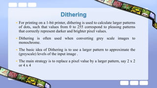
![ reasonably accurate color images can be obtained by quantizing the color information to collapse it.
Color quantizing example: reducing the number of colors required to represent a digital image makes
it possible to reduce its file size.
Many systems can make use of 8 bits of color information (the so-called “256 colors”) in producing a
screen image
8-bit color image files use the concept of a lookup table to store color information. 8-bit color image
(so-called 256 colors. Why?) files use the concept of a lookup table (LUT) to store color
information. For example,:
if exactly 23 pixels have RGB values (45, 200, 91)
then store the value 23 in a three-dimensional array, at the element indexed by the index values [45,
200, 91].
This data structure is called a color histogram. color histogram: is a very useful tool for image
transformation and manipulation in Image Processing.](https://image.slidesharecdn.com/multimediagraphicsandimagedatarepresentation-170929142352/85/Multimedia-graphics-and-image-data-representation-22-320.jpg)