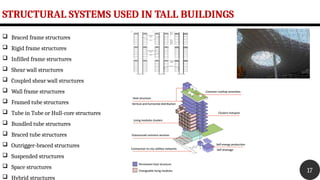
INTRODUCTION
TO
TALL
STRUCTURES
DR.SHALINI R NAIR
INTRODUCTION
 A tall building can be defined as a structure that has the ratio of
‘height of building to lateral dimension more than 5.0
 If the natural frequency of the building in the first mode is less
than 1.0 Hz - to be investigated to ascertain the importance of
wind induced oscillations. (IS 875: Part 3)
 Recent trend - To build taller, slimmer, and lighter structures.
 Lighter systems - more prone to vibrations, which can cause
discomfort, damages and structural failure.
2
DEMAND FOR
HIGH RISE
BUILDINGS
33
Scarcity of land in urban areas
Increasing demand for business and residential
space
Economic growth
Technological advancements
Innovations in structural systems
Desire for aesthetics in urban settings
Concept of city skyline
Cultural significance and prestige
Human Aspiration to build higher
ACTIVITY 1
44
List out 5 tallest building in world
List out 5 tallest infrastructure in India
55
Burj Khalifa,
which is
located in
Dubai.
829.8 m --
2009
KVLY-TV mast, Blanchard, North Dakota, United States, 628.8 m-- 1963
TALLEST STATUE
6
6
Statue of Unity, India - 2018
Tall Building and
its Support
Structure
77
Development of Structural Systems
Structural System Classification
Tall Building Trends
Structural Systems Used In Tall Buildings -
Detailed Study.
Structural system in a building can be defined as, the particular method of assembling
and constructing structural elements of a building so that they support and transmit
applied loads safely to the ground without exceeding the allowable stresses in the
members.
The term structural system or structural frame in structural engineering refers to load
resisting sub system of a structure. The structural systems transfers load through
interconnected structural components or members.
Collection or assemblage of materials that, when joined together, will withstand the
loads and forces to which they are subjected. These loads are not confined just to the
weight of the building itself, but will also include such forces as wind & earthquake
Tall Building and its Support Structure
1
2
3
8
Tall Building and its Support Structure
9
DEVELOPMENT OF STRUCTURAL SYSTEMS
10
First Generation1780-1850
The exterior walls of these buildings consisted of stone or brick,
although sometimes cast iron was added for decorative purposes.
The columns were constructed of cast iron, often unprotected; steel
and wrought iron was used for the beams; and the floors were made of
wood.
Second Generation 1850-1940
The second generation of tall buildings, which includes the
Metropolitan Life Building (1909), the Woolworth Building (1913), and
the Empire State Building (1931), are frame structures, in which a
skeleton of welded- or riveted-steel columns and beams, often encased
in concrete, runs through the entire building. This type of construction
makes for an extremely strong structure, but not such attractive floor
space. The interiors are full of heavy, load-bearing columns and walls.
HOME
INSURANCE
BUILDING
EMPIRE STATE
BUILDING
DEVELOPMENT OF STRUCTURAL SYSTEMS
11
Third Generation 1940-present
 Buildings constructed from after World War II until today make up the most recent
generation of high-rise buildings.
 Within this generation there are those of steel-framed construction(core construction and
tube construction), reinforced concrete construction(shear wall), and steel-framed reinforced
concrete construction .
 Hybrid systems also evolved during this time. These systems make use more than one type of
structural system in a building.
STRUCTURAL SYSTEM CLASSIFICATION
12
TALL BUILDING TRENDS
13
Considering the worlds 100 tallest buildings in 1990:
 80 percent were located in North America.
 Almost 90 percent were exclusively office use.
 More than half were constructed of steel.
In 2013, for the world's 100 tallest buildings:
 The largest share (43 percent) are now in Asia. (Only one new 200-m-plus building was
built in North America in 2013, compared to 54 in Asia.)
 Less than 50 percent are exclusively office use. Almost a quarter are mixed-use and 14
percent are residential.
 Almost half were constructed of reinforced concrete and only 14 percent of steel. (The
remaining are composite or mixed structural materials.)
TALL BUILDING TRENDS
14
A composite tall building utilizes a
combination of both steel and concrete
acting compositely in the main structural
elements.
A mixed—structure tall building is any
building that utilizes distinct steel or
concrete systems above or below each
other.
Structural material usage from 1930 to 2013
STRUCTURAL SYSTEMS USED IN TALL BUILDINGS
15
 Braced frame structures
 Rigid frame structures
 Infilled frame structures
 Shear wall structures
 Coupled shear wall structures
 Wall frame structures
 Framed tube structures
 Tube in Tube or Hull-core structures
 Bundled tube structures
 Braced tube structures
 Outrigger-braced structures
 Suspended structures
 Space structures
 Hybrid structures
STRUCTURAL SYSTEMS USED IN TALL BUILDINGS
16
 Braced frame structures
 Rigid frame structures
 Infilled frame structures
 Shear wall structures
 Coupled shear wall structures
 Wall frame structures
 Framed tube structures
 Tube in Tube or Hull-core structures
 Bundled tube structures
 Braced tube structures
 Outrigger-braced structures
 Suspended structures
 Space structures
 Hybrid structures
STRUCTURAL SYSTEMS USED IN TALL BUILDINGS
17
 Braced frame structures
 Rigid frame structures
 Infilled frame structures
 Shear wall structures
 Coupled shear wall structures
 Wall frame structures
 Framed tube structures
 Tube in Tube or Hull-core structures
 Bundled tube structures
 Braced tube structures
 Outrigger-braced structures
 Suspended structures
 Space structures
 Hybrid structures
Braced frame structures
18
 A braced frame is a very strong structural system that is commonly used in
structures subject to lateral loads such as wind and seismic pressure.
 The members in a braced frame are generally made of structural steel,
which can work effectively both in tension and compression.
 The beams and columns that form the frame carry vertical loads, and the
bracing system carries the lateral loads.
 The positioning of braces, however, can be problematic as they can
interfere with the design of the façade and the positioning of openings.
 Buildings adopting high-tech or post-modernist styles have responded to
this by expressing the bracing as an internal or external architectural
feature.
Braced frame structures
19
Vertical and horizontal bracing systems
 The resistance to horizontal forces is provided by two bracing systems; vertical and horizontal bracing:
Vertical bracing
 Bracing between column lines (in vertical planes) provides load paths for the transference of horizontal forces
to ground level. Framed buildings require at least three planes of vertical bracing to brace both directions in
plan and to resist torsion about a vertical axis.
Horizontal bracing
 Bracing at each floor (in horizontal planes) provides load paths for the transference of horizontal forces to the
planes of vertical bracing. Horizontal bracing is needed at each floor level, however, the floor system itself may
provide sufficient resistance. Roofs may also require bracing.
Rigid frame structures
20
 In structural engineering, a rigid frame is the load-resisting skeleton
constructed with straight or curved members interconnected by mostly rigid
connections, which resist movements induced at the joints of members. Its
members can take bending moment, shear, and axial loads.
 Rigid frames are characterized by the lack of pinned joints within the frame,
and typically statically indeterminate.
 A rigid frame is capable of resisting both vertical and lateral loads by the
bending of beams and columns. Stiffness of the rigid frame is provided
mainly by the bending rigidity of beams and columns that have rigid
connections. The joints shall be designed in such a manner that they have
adequate strength and stiffness and negligible deformation.
Infilled frame structures
21
 Infill frame structure comprises of the reinforced beam and column frame in which
the vertical space is infilled with brick masonry or concrete block work
 Infill frames are commonly used for low and medium-height buildings all over the
world.
 Used for buildings up to 30 stories.
 A framework of beams and columns in which some bays of frames are infilled with
masonry walls that may or may not be mechanically connected to the frame. Due to
great stiffness and strength in their planes, infill walls do not allow the beams and
columns to bend under horizontal loading, changing the structural performance of
the frame. During an earthquake, diagonal compression struts form in the infills so
the structure behaves more like a Braced Frame rather than a Moment Frame. Infill
walls can be part-height or completely fill the frame.
Infilled frame structures
22
Shear Wall structures
23
Reinforced concrete wall
 Designed to resist lateral forces
 Excellent structural system to resist earthquake
 Provided throughout the entire height of wall
 Practicing from 1960s for medium and high-rise buildings (4 to 35 stories
high)
 Provide large strength and stiffness in the direction of orientation
 Significantly reduces lateral sway
 Easy construction and implementation
 Efficient in terms of construction cost and effectiveness in minimizing
earthquake damage
Shear Wall structures
24
PLACEMENT OF SHEAR WALL
 Located symmetrically to reduce ill
effects of twist
 Symmetry can be along one or both
the directions
 Can be located at exterior or interior
 More effective when located along
exterior perimeter of building
Fig. 2 Reinforced concrete shear wall
X
Y
Shear Wall structures
25
Coupled Shear Wall structures
26
 Coupled shear walls consist of two shear walls connected intermittently by beams along the height. The
behavior of coupled shear walls is mainly governed by the coupling beams.
 The coupling beams are designed for ductile inelastic behavior in order to dissipate energy.
 When two or more shear walls are connected by a system of beams or slabs, total stiffness exceeds the
summation of individual stiffness. This is because the connecting beam restrains individual cantilever action.
Coupled Shear Wall structures
27
 Openings normally occur in vertical rows throughout the height of the wall and the connection between wall
cross-sections is provided either by connecting beams which form part of the wall or floor slab or a combination
of both.
 The terms ‘coupled shear walls’, ‘pierced shear walls’ and ‘shear wall with openings’ are commonly described for
such units.
 If the openings are very small, their effect on the overall state of stress in the shear wall is minimal.
 Large openings have a pronounced effect and if large enough result in a system in which frame action
predominates.
Wall frame structures
28
 Wall-frame structures is a combination of shear walls
and rigid frames.
 It is suited for buildings of up to 50 storey or more.
 It is possible to design shear walls as cores that
surround elevator shafts and stairwells
 Closed and partially closed cores can increase the
stiffness of the building laterally and against torsion.
 Shear walls are of reinforced concrete or
composite(concrete encased structural steel or steel
plates).
Wall frame structures
29
 Columns and beams are reinforced concrete, structural
steel or composite.
 At the top, frame is subjected to a significant positive
shear, which is balanced by an equal negative shear at
the top of the wall, with a corresponding connected
interaction force acting between the frame and the wall.
 The horizontal interaction can be effective in
contributing to lateral stiffness to the extend that wall-
frames of up to50 storey or more are economical.
 The potential advantages of a wall-frame structure
depend on the amount of horizontal interaction.
Framed tube structures
30
 A tubular structural system is used in high-rise buildings to
resist lateral loads like wind and seismic forces.
 These lateral load resisting systems let the building behave
like a hollow cylindrical tube cantilevered perpendicular to
the ground. Thus, the structure exhibits a tubular behavior
against the lateral loads.
 The tube system was developed by the famous structural
designer Fazlur Rahman Khan in 1960. He is considered the
father of tubular design in structural engineering.
 The DeWitt Chestnut Apartment Building in Chicago was
the first tube-frame structure designed by Khan in 1963.
Framed tube structures
31
 The framed tube system is Khan’s simplest and first tubular
structural system.
 The framed tube can be used for various floor plan shapes like
square, circular, rectangular, and freeform.
 Framed tube structural system consists of closely spaced exterior
columns that are rigidly connected with deep spandrel beams
running continuously along each facade and around the building
corners. This arrangement increases the beam and column stiffness
by decreasing the clear span dimensions and increasing the member
depth.
 This type is efficient for buildings with a height from 38 to 300 m.
Framed tube structures
32
Tube in Tube or Hull-core structures
33
 Tube-in-tube structural system is also known as “hull and core” arrangement.
 A core tube is surrounded by an exterior tube.
 The core tube holds the critical elements of a high-rise building like lifts, ducts, stairs, etc.
 The exterior tube is the usual tube system that takes the majority of gravity and lateral loads.
 In this system, the inner and outer tubes interact horizontally as shear and flexural components.
Bundled tube structures
34
 In bundled tube structural system, there are several
interconnected tubes to form a multi-cell tube.
 This arrangement together resists lateral loads and
overturning moments.
 The tube-in-tube system is the most economical and
versatile building design that helps to create interesting
shapes.
 Willis Tower in Chicago is the first building to adopt
tube-in-tube structural design.
Bundled tube structures
35
Braced tube structures
36
 Braced tube structures are also known as Trussed tube structural
system.
 Trussed tube structural systems like frame tube systems consist of
exterior columns fewer in number compared to framed tube
systems that are placed far apart.
 These columns are connected using steel bracing or concrete shear
walls.
 This interconnection of exterior columns makes a rigid box capable
of resisting lateral shear by axial force in members rather than
bending or curving (flexure).
 The provision of broad column spacing in the trussed tube system
allows clear space for windows.
Outrigger-braced structures
37
 The core may be centrally located with outriggers
extending on both sides or in some cases it may be located
on one side of the building with outriggers extending to
the building columns on the other side
 The outriggers are generally in the form of trusses (1 or 2
story deep) in steel structures, or walls in concrete
structures, that effectively act as stiff headers inducing a
tension-compression couple in the outer columns.
 Belt trusses are often provided to distribute these tensile
and compressive forces to a large number of exterior
frame columns.
 Build up to 150 floors
Shangai World
financial centre
Suspended structures
38
 Suspended Structures are those with horizontal planes i.e. floors are
supported by cables (hangers) hung from the parabolic sag of large,
high-strength steel cables.
 The strength of a suspended structure is derived from the parabolic
form of the sagging high strength cable.
 To make this structure more efficient, the parabolic form is so
designed that its shape closely follows the exact form of the moment
diagrams.
 The sagging cable is more stable under symmetrical loading
conditions as the cable may deform as it attempts to adjust to an
eccentric loading.
 As the cable adjusts to this load its shifts the rest of the structure. Core Suspended Building
Suspended structures
39
 This adjustment causes secondary stresses in the horizontal surface and additional deformation.
 The parabolic curve of the cable is also designed for various eccentric or lateral loads such as wind, seismic etc.
 The large curving cable may consist of many smaller cables which are tightly spun together.
 As the cables are being spun together, they are also stretched over the span and attached to the supports.
 After being assembled, the appropriate curve is created by tensioning the cable.
 The horizontal surfaces supported by the cable are hung piece by piece from the sagging cable. Usually, the
horizontal surfaces are made of steel because of its lightweight property.
 Lightweight concrete mixtures are also used.
 The towers from where the cables are hung may be of steel, concrete.
 The cables are made up of steel.
Space structures
40
 Space truss structures are modified braced tubes with diagonals
connecting the exterior to interior.
 In a typical braced tube structure, all the diagonals, which connect
the chord members – vertical corner columns in general, are located
on the plane parallel to the facades.
 However, in space trusses, some diagonals penetrate the interior of
the building.
Bank of China, Hong Kong
Hybrid structures
41
Super frame structures
• Super frame structures can create ultra high-rise buildings up to
160 floors.
• Super frames or Mega frames assume the form of a portal which
is provided on the exterior of a building.
• The frames resist all wind forces as an exterior tubular structure.
• The portal frame of the Superframe is composed of vertical legs in
each corner of the building which are linked by horizontal
elements at about every 12 to 14 floors.
• Since the vertical elements are concentrated in the corner areas
of the building, maximum efficiency is obtained for resisting wind
forces.
42
Development of Structural Support System for High Rise Buildings
43
Loads and its
Components in
Tall Structure
44
44
Loads acting on a building
Difference for High Rise and Low-Rise
Building
Loads and Load Reduction
 Dead Loads
 Live Loads
 Seismic Loads
 Wind Loads
 Impact Loads
 Construction loads
Loads acting on a building
45
Loading on tall structures differ from low rise building in following aspects:
Large accumulation of gravity loads on floors from top to bottom.
Significance of Wind loading
Importance of Dynamic Loading
Loading: Difference for High Rise and Low-Rise Building
1
2
3
46
 Dead loads can be assessed accurately
 Live loads - anticipated approximately from a combination
of experience and previous field observations
Gravity Loads and Lateral Loads
47
Gravity Loads
Lateral Loads
 Wind and Earthquake – random in nature –
difficult to predict – estimated based on
probabilistic approach.
DL - weight imposed by structure itself.
 Constant throughout – unless and until it undergoes renovation.
 Can be predicted
 Calculated from member sizes and estimated material properties.
LL - Occupancy load – imposes gravitational effects.
 Changes according to occupancy of floors.
 Include effect of people and furniture.
 Can be estimated
 Code provisions – empirical and conservative based on experience and accepted practice
 IS : 875 Part-II
Load Estimation
48
Live load
49
OCCUPANCY
CLASSIFICATION
UNIFORMLELY
DISTRIBUTED LOAD
kN/m²
CONCENTRATED LOAD (kN)
OFFICE BUILDINGS
OFFICES &STAFF ROOMS 2.5 2.7
CLASSROOMS 3 2.7
CORRIDORS,STORE & READING
ROOMS
4 4.5
RESIDENTIAL BUILDINGS
APARTMRNTS 2 1.8
RESTAURANTS 4 2.7
CORRIDORS 3 4.5
GRAVITY LOADS – REDUCTION - LL
50
Columns & Load baring walls
Done only if there is no specific load – plant or machinery on floor
Supporting members of roof – 100% UDL
Each successive floors – 10 % reductions
Minimum – 50% reduction
LL at floors – beams and girders – 5% reduction – 50 m² - maximum
reduction 25%
50
REDUCTION - LL
 NATIONAL BUILDING CODE OF INDIA
Percentage Method
All possible LL applied on floors and roof – divided into 3
load groups.
Load group 1:
Comprises of UDL arising from
Assembly occupancies or areas with UDL (LL)
5kN/m² or less
51
REDUCTION - LL
Machinery or equipment for which
specific live load allowances are made.
Special purpose roofs which are used
for assembly purpose, garden etc.
Printing plants, Strong rooms etc
Load group 2:
Assembly occupancies or areas with
UDL (LL) greater than 5kN/m²
52
REDUCTION - LL
No live load reduction is permitted for members
under Load group 1
Live load reduction factor for Load group 2 :
• 1=R=0.7
• R=0.6+√(8/At)
• At – Sum of all tributary areas in square
meters.
53
REDUCTION - LL
Live load reduction factor for Load group 3 :
• 1=R=0.5
• R=0.25+√(14/At)
• At – Sum of all tributary areas in square meters.
54
IMPACT LOADS
 Elevators – being accelerated upward or brought to rest
down
Increase of 100% of static elevator load used – for satisfactory
performance
55
CONSTRUCTION LOADS
 Most severe loads – building – withstand
Construction loads:
 Weight of floor forms
Newly placed slabs(twice floor DL)
Climbing crane
 Loads supported by props
If not considered during planning – increases cost of construction.
56
EARTHQUAKE LOADS
 Consists of inertial forces - resulting from – shaking of its foundation
by seismic disturbance
Principles – Design philosophy of EQR design:
 Resists minor EQ without damage
Resist moderate EQ without structural damage but accepting
probability of non structural damage
Resist avg EQ allowing both but without damage
57
EARTHQUAKE LOAD COMBINATIONS
 Steel Structures – Plastic Design
1.7(DL +IL)
1.7(DL+ EL)
1.3(DL + IL +EL)
 RC structures/PC structures – Limit State Design
1.5(DL +IL)
1.5(DL+ EL)
1.2(DL + IL +EL)
0.9L +1.5 EL 58
PROVISIONS – SEISMIC CODE
More than half of area in India is susceptible to EQ shaking
First step in EQ resistant construction was in 1935
1935 Balochistan earthquake – Quetta – now part of Pakistan –
Magnitude 7.7 Mw (Moment magnitude Scale)
Steps for first seismic code – 1960
Published – IS 1893 - 1962
59
PROVISIONS – SEISMIC CODE
Revisions :
1966
1970
1975
1984
2002
Code to specify construction and detailing – IS 4326:1967
60
PROVISIONS – SEISMIC CODE
Revisions :
1966
1970
1975
1984
2002
Code to specify construction and detailing – IS 4326:1967
61
WIND LOADING
62
WIND LOADING
63
WIND LOADING
64
WIND LOADING
65
WIND LOADING
66
WATER AND EARTH PRESSURE LOADS
67
 Liquids produce horizontal loads in many structures.
 The horizontal pressure of a liquid increases linearly with depth and is proportional to the density of the liquid.
This is similar for earth pressures.
 The load due to earth pressure varies with its depth, any surcharge, the type of soil and its moisture content.
 The design live load for this soil pressure must not be less than that which would be caused by a fluid weighing
1.43kN/m3
LOADS DUE TO RESTRAINED VOLUME
68
 Shrinkage of concrete is primarily due to drying of newly built concrete elements. Most concrete shrinkage
takes place early in the life of the structure.
 Creep (continuing shrinkage of concrete over time under constant compression loads) is present in all post-
tensioned structure where the force of the post-tensioning tendon produces pre-compression of concrete
elements. The rate of creep deformation is slower than the rate of shrinkage.
 Concrete elements also expand and contract in proportion to temperature variation. The length of longer
concrete elements will commonly vary by several inches due to the combined influences of shrinkage, creep,
and temperature change.
 If these effects are not fully recognized, and the volume changes are not accommodated either by design or by
allowing for the expected movement, parts of the structure could be distressed. A typical example of restrained
volume changes is a design that creates a short column in a relatively long structure. This often happens in
parking decks, especially when sloping ramp geometry results in variable column lengths.
IMPACT LOADS
69
 Sudden load acting on a structure in short duration.
 Earthquake is one of the impact load acting on a structure
 An impact load is one whose time of application on a
material is less than one-third of the natural period of
vibration of that material.
 Cyclic loads on a structure can led to fatigue damage,
cumulative damage, or failure.
 These loads can be repeated loadings on a structure or can
be due to vibration.
Impact Load is calculated as
total Kinetic Energy
Dissipation divided by local
deformation.
BLAST LOADS
70
 Load applied to a structure from a blast wave that
comes immediately after an explosion.
 It is the combination of overpressure and either
impulse or duration.
 A high blast load can cause catastrophic damage to a
building, both internally and externally, and can be
fatal to building occupants
BLAST LOADS vs SEISMIC LOADS
71
GENERAL REQUIREMENTS FOR DESIGN OF TALL STRUCTURES
72
 Height limitations of different structural systems,
 Elevation and plan aspect ratios
 Lateral drift,
 Storey stiffness and strength
 Density of buildings
 Modes of vibration
 Floor systems
 Materials, and
 Progressive collapse mechanism
GENERAL REQUIREMENTS FOR DESIGN OF TALL STRUCTURES
73
 Height limitations of different structural systems,
 Elevation and plan aspect ratios
 Lateral drift,
 Storey stiffness and strength
 Density of buildings
 Modes of vibration
 Floor systems
 Materials, and
 Progressive collapse mechanism
GENERAL REQUIREMENTS FOR DESIGN OF TALL STRUCTURES
74
 Height limitations of different structural systems
The maximum
building height
(in m) shall not
exceed
values given in
Table 1 for
buildings with
different
structural
systems.
GENERAL REQUIREMENTS FOR DESIGN OF TALL STRUCTURES
75
 Elevation and plan aspect ratios
Plan Geometry
5.2.1.1 The plan shall preferably be rectangular (including square) or elliptical (including circular).
In buildings with said plan geometries, structural members participate efficiently in resisting lateral loads
without causing additional effects arising out of re-entrant corners and others.
Plan Aspect Ratio
The maximum plan aspect ratio (Lt/Bt) of the overall building shall not exceed 5.0.
In case of an L shaped building, Lt and Bt shall refer to the respective length and width of each leg of the
building.
GENERAL REQUIREMENTS FOR DESIGN OF TALL STRUCTURES
76
Lateral drift
 When design lateral forces are applied on the building, the maximum inter-storey elastic lateral drift ratio
 ( max /hi) under working loads (unfactored wind load combinations with return period of 50 years) which is
Δ
estimated based on realistic section properties, shall be limited to H/500.
 For a single storey the drift limit may be relaxed to hi/400.
 For earthquake load (factored) combinations the drift shall be limited to hi/250.
GENERAL REQUIREMENTS FOR DESIGN OF TALL STRUCTURES
77
 Storey stiffness and strength
Parameters influencing stiffness and strength of the building should be so proportioned, that the following are
maintained:
a) Lateral translational stiffness of any storey shall not be less than 70 percent of that of the storey above.
b) Lateral translational strength of any storey shall not be less than that of the storey above.
THANK YOU shalinirncivil@gmail.com

Introduction to Tall_Structures_Structural demands_Structural Systems_Loads on Tall Structures.pptx

  • 1.
  • 2.
    INTRODUCTION  A tallbuilding can be defined as a structure that has the ratio of ‘height of building to lateral dimension more than 5.0  If the natural frequency of the building in the first mode is less than 1.0 Hz - to be investigated to ascertain the importance of wind induced oscillations. (IS 875: Part 3)  Recent trend - To build taller, slimmer, and lighter structures.  Lighter systems - more prone to vibrations, which can cause discomfort, damages and structural failure. 2
  • 3.
    DEMAND FOR HIGH RISE BUILDINGS 33 Scarcityof land in urban areas Increasing demand for business and residential space Economic growth Technological advancements Innovations in structural systems Desire for aesthetics in urban settings Concept of city skyline Cultural significance and prestige Human Aspiration to build higher
  • 4.
    ACTIVITY 1 44 List out5 tallest building in world List out 5 tallest infrastructure in India
  • 5.
    55 Burj Khalifa, which is locatedin Dubai. 829.8 m -- 2009 KVLY-TV mast, Blanchard, North Dakota, United States, 628.8 m-- 1963
  • 6.
    TALLEST STATUE 6 6 Statue ofUnity, India - 2018
  • 7.
    Tall Building and itsSupport Structure 77 Development of Structural Systems Structural System Classification Tall Building Trends Structural Systems Used In Tall Buildings - Detailed Study.
  • 8.
    Structural system ina building can be defined as, the particular method of assembling and constructing structural elements of a building so that they support and transmit applied loads safely to the ground without exceeding the allowable stresses in the members. The term structural system or structural frame in structural engineering refers to load resisting sub system of a structure. The structural systems transfers load through interconnected structural components or members. Collection or assemblage of materials that, when joined together, will withstand the loads and forces to which they are subjected. These loads are not confined just to the weight of the building itself, but will also include such forces as wind & earthquake Tall Building and its Support Structure 1 2 3 8
  • 9.
    Tall Building andits Support Structure 9
  • 10.
    DEVELOPMENT OF STRUCTURALSYSTEMS 10 First Generation1780-1850 The exterior walls of these buildings consisted of stone or brick, although sometimes cast iron was added for decorative purposes. The columns were constructed of cast iron, often unprotected; steel and wrought iron was used for the beams; and the floors were made of wood. Second Generation 1850-1940 The second generation of tall buildings, which includes the Metropolitan Life Building (1909), the Woolworth Building (1913), and the Empire State Building (1931), are frame structures, in which a skeleton of welded- or riveted-steel columns and beams, often encased in concrete, runs through the entire building. This type of construction makes for an extremely strong structure, but not such attractive floor space. The interiors are full of heavy, load-bearing columns and walls. HOME INSURANCE BUILDING EMPIRE STATE BUILDING
  • 11.
    DEVELOPMENT OF STRUCTURALSYSTEMS 11 Third Generation 1940-present  Buildings constructed from after World War II until today make up the most recent generation of high-rise buildings.  Within this generation there are those of steel-framed construction(core construction and tube construction), reinforced concrete construction(shear wall), and steel-framed reinforced concrete construction .  Hybrid systems also evolved during this time. These systems make use more than one type of structural system in a building.
  • 12.
  • 13.
    TALL BUILDING TRENDS 13 Consideringthe worlds 100 tallest buildings in 1990:  80 percent were located in North America.  Almost 90 percent were exclusively office use.  More than half were constructed of steel. In 2013, for the world's 100 tallest buildings:  The largest share (43 percent) are now in Asia. (Only one new 200-m-plus building was built in North America in 2013, compared to 54 in Asia.)  Less than 50 percent are exclusively office use. Almost a quarter are mixed-use and 14 percent are residential.  Almost half were constructed of reinforced concrete and only 14 percent of steel. (The remaining are composite or mixed structural materials.)
  • 14.
    TALL BUILDING TRENDS 14 Acomposite tall building utilizes a combination of both steel and concrete acting compositely in the main structural elements. A mixed—structure tall building is any building that utilizes distinct steel or concrete systems above or below each other. Structural material usage from 1930 to 2013
  • 15.
    STRUCTURAL SYSTEMS USEDIN TALL BUILDINGS 15  Braced frame structures  Rigid frame structures  Infilled frame structures  Shear wall structures  Coupled shear wall structures  Wall frame structures  Framed tube structures  Tube in Tube or Hull-core structures  Bundled tube structures  Braced tube structures  Outrigger-braced structures  Suspended structures  Space structures  Hybrid structures
  • 16.
    STRUCTURAL SYSTEMS USEDIN TALL BUILDINGS 16  Braced frame structures  Rigid frame structures  Infilled frame structures  Shear wall structures  Coupled shear wall structures  Wall frame structures  Framed tube structures  Tube in Tube or Hull-core structures  Bundled tube structures  Braced tube structures  Outrigger-braced structures  Suspended structures  Space structures  Hybrid structures
  • 17.
    STRUCTURAL SYSTEMS USEDIN TALL BUILDINGS 17  Braced frame structures  Rigid frame structures  Infilled frame structures  Shear wall structures  Coupled shear wall structures  Wall frame structures  Framed tube structures  Tube in Tube or Hull-core structures  Bundled tube structures  Braced tube structures  Outrigger-braced structures  Suspended structures  Space structures  Hybrid structures
  • 18.
    Braced frame structures 18 A braced frame is a very strong structural system that is commonly used in structures subject to lateral loads such as wind and seismic pressure.  The members in a braced frame are generally made of structural steel, which can work effectively both in tension and compression.  The beams and columns that form the frame carry vertical loads, and the bracing system carries the lateral loads.  The positioning of braces, however, can be problematic as they can interfere with the design of the façade and the positioning of openings.  Buildings adopting high-tech or post-modernist styles have responded to this by expressing the bracing as an internal or external architectural feature.
  • 19.
    Braced frame structures 19 Verticaland horizontal bracing systems  The resistance to horizontal forces is provided by two bracing systems; vertical and horizontal bracing: Vertical bracing  Bracing between column lines (in vertical planes) provides load paths for the transference of horizontal forces to ground level. Framed buildings require at least three planes of vertical bracing to brace both directions in plan and to resist torsion about a vertical axis. Horizontal bracing  Bracing at each floor (in horizontal planes) provides load paths for the transference of horizontal forces to the planes of vertical bracing. Horizontal bracing is needed at each floor level, however, the floor system itself may provide sufficient resistance. Roofs may also require bracing.
  • 20.
    Rigid frame structures 20 In structural engineering, a rigid frame is the load-resisting skeleton constructed with straight or curved members interconnected by mostly rigid connections, which resist movements induced at the joints of members. Its members can take bending moment, shear, and axial loads.  Rigid frames are characterized by the lack of pinned joints within the frame, and typically statically indeterminate.  A rigid frame is capable of resisting both vertical and lateral loads by the bending of beams and columns. Stiffness of the rigid frame is provided mainly by the bending rigidity of beams and columns that have rigid connections. The joints shall be designed in such a manner that they have adequate strength and stiffness and negligible deformation.
  • 21.
    Infilled frame structures 21 Infill frame structure comprises of the reinforced beam and column frame in which the vertical space is infilled with brick masonry or concrete block work  Infill frames are commonly used for low and medium-height buildings all over the world.  Used for buildings up to 30 stories.  A framework of beams and columns in which some bays of frames are infilled with masonry walls that may or may not be mechanically connected to the frame. Due to great stiffness and strength in their planes, infill walls do not allow the beams and columns to bend under horizontal loading, changing the structural performance of the frame. During an earthquake, diagonal compression struts form in the infills so the structure behaves more like a Braced Frame rather than a Moment Frame. Infill walls can be part-height or completely fill the frame.
  • 22.
  • 23.
    Shear Wall structures 23 Reinforcedconcrete wall  Designed to resist lateral forces  Excellent structural system to resist earthquake  Provided throughout the entire height of wall  Practicing from 1960s for medium and high-rise buildings (4 to 35 stories high)  Provide large strength and stiffness in the direction of orientation  Significantly reduces lateral sway  Easy construction and implementation  Efficient in terms of construction cost and effectiveness in minimizing earthquake damage
  • 24.
    Shear Wall structures 24 PLACEMENTOF SHEAR WALL  Located symmetrically to reduce ill effects of twist  Symmetry can be along one or both the directions  Can be located at exterior or interior  More effective when located along exterior perimeter of building
  • 25.
    Fig. 2 Reinforcedconcrete shear wall X Y Shear Wall structures 25
  • 26.
    Coupled Shear Wallstructures 26  Coupled shear walls consist of two shear walls connected intermittently by beams along the height. The behavior of coupled shear walls is mainly governed by the coupling beams.  The coupling beams are designed for ductile inelastic behavior in order to dissipate energy.  When two or more shear walls are connected by a system of beams or slabs, total stiffness exceeds the summation of individual stiffness. This is because the connecting beam restrains individual cantilever action.
  • 27.
    Coupled Shear Wallstructures 27  Openings normally occur in vertical rows throughout the height of the wall and the connection between wall cross-sections is provided either by connecting beams which form part of the wall or floor slab or a combination of both.  The terms ‘coupled shear walls’, ‘pierced shear walls’ and ‘shear wall with openings’ are commonly described for such units.  If the openings are very small, their effect on the overall state of stress in the shear wall is minimal.  Large openings have a pronounced effect and if large enough result in a system in which frame action predominates.
  • 28.
    Wall frame structures 28 Wall-frame structures is a combination of shear walls and rigid frames.  It is suited for buildings of up to 50 storey or more.  It is possible to design shear walls as cores that surround elevator shafts and stairwells  Closed and partially closed cores can increase the stiffness of the building laterally and against torsion.  Shear walls are of reinforced concrete or composite(concrete encased structural steel or steel plates).
  • 29.
    Wall frame structures 29 Columns and beams are reinforced concrete, structural steel or composite.  At the top, frame is subjected to a significant positive shear, which is balanced by an equal negative shear at the top of the wall, with a corresponding connected interaction force acting between the frame and the wall.  The horizontal interaction can be effective in contributing to lateral stiffness to the extend that wall- frames of up to50 storey or more are economical.  The potential advantages of a wall-frame structure depend on the amount of horizontal interaction.
  • 30.
    Framed tube structures 30 A tubular structural system is used in high-rise buildings to resist lateral loads like wind and seismic forces.  These lateral load resisting systems let the building behave like a hollow cylindrical tube cantilevered perpendicular to the ground. Thus, the structure exhibits a tubular behavior against the lateral loads.  The tube system was developed by the famous structural designer Fazlur Rahman Khan in 1960. He is considered the father of tubular design in structural engineering.  The DeWitt Chestnut Apartment Building in Chicago was the first tube-frame structure designed by Khan in 1963.
  • 31.
    Framed tube structures 31 The framed tube system is Khan’s simplest and first tubular structural system.  The framed tube can be used for various floor plan shapes like square, circular, rectangular, and freeform.  Framed tube structural system consists of closely spaced exterior columns that are rigidly connected with deep spandrel beams running continuously along each facade and around the building corners. This arrangement increases the beam and column stiffness by decreasing the clear span dimensions and increasing the member depth.  This type is efficient for buildings with a height from 38 to 300 m.
  • 32.
  • 33.
    Tube in Tubeor Hull-core structures 33  Tube-in-tube structural system is also known as “hull and core” arrangement.  A core tube is surrounded by an exterior tube.  The core tube holds the critical elements of a high-rise building like lifts, ducts, stairs, etc.  The exterior tube is the usual tube system that takes the majority of gravity and lateral loads.  In this system, the inner and outer tubes interact horizontally as shear and flexural components.
  • 34.
    Bundled tube structures 34 In bundled tube structural system, there are several interconnected tubes to form a multi-cell tube.  This arrangement together resists lateral loads and overturning moments.  The tube-in-tube system is the most economical and versatile building design that helps to create interesting shapes.  Willis Tower in Chicago is the first building to adopt tube-in-tube structural design.
  • 35.
  • 36.
    Braced tube structures 36 Braced tube structures are also known as Trussed tube structural system.  Trussed tube structural systems like frame tube systems consist of exterior columns fewer in number compared to framed tube systems that are placed far apart.  These columns are connected using steel bracing or concrete shear walls.  This interconnection of exterior columns makes a rigid box capable of resisting lateral shear by axial force in members rather than bending or curving (flexure).  The provision of broad column spacing in the trussed tube system allows clear space for windows.
  • 37.
    Outrigger-braced structures 37  Thecore may be centrally located with outriggers extending on both sides or in some cases it may be located on one side of the building with outriggers extending to the building columns on the other side  The outriggers are generally in the form of trusses (1 or 2 story deep) in steel structures, or walls in concrete structures, that effectively act as stiff headers inducing a tension-compression couple in the outer columns.  Belt trusses are often provided to distribute these tensile and compressive forces to a large number of exterior frame columns.  Build up to 150 floors Shangai World financial centre
  • 38.
    Suspended structures 38  SuspendedStructures are those with horizontal planes i.e. floors are supported by cables (hangers) hung from the parabolic sag of large, high-strength steel cables.  The strength of a suspended structure is derived from the parabolic form of the sagging high strength cable.  To make this structure more efficient, the parabolic form is so designed that its shape closely follows the exact form of the moment diagrams.  The sagging cable is more stable under symmetrical loading conditions as the cable may deform as it attempts to adjust to an eccentric loading.  As the cable adjusts to this load its shifts the rest of the structure. Core Suspended Building
  • 39.
    Suspended structures 39  Thisadjustment causes secondary stresses in the horizontal surface and additional deformation.  The parabolic curve of the cable is also designed for various eccentric or lateral loads such as wind, seismic etc.  The large curving cable may consist of many smaller cables which are tightly spun together.  As the cables are being spun together, they are also stretched over the span and attached to the supports.  After being assembled, the appropriate curve is created by tensioning the cable.  The horizontal surfaces supported by the cable are hung piece by piece from the sagging cable. Usually, the horizontal surfaces are made of steel because of its lightweight property.  Lightweight concrete mixtures are also used.  The towers from where the cables are hung may be of steel, concrete.  The cables are made up of steel.
  • 40.
    Space structures 40  Spacetruss structures are modified braced tubes with diagonals connecting the exterior to interior.  In a typical braced tube structure, all the diagonals, which connect the chord members – vertical corner columns in general, are located on the plane parallel to the facades.  However, in space trusses, some diagonals penetrate the interior of the building. Bank of China, Hong Kong
  • 41.
  • 42.
    Super frame structures •Super frame structures can create ultra high-rise buildings up to 160 floors. • Super frames or Mega frames assume the form of a portal which is provided on the exterior of a building. • The frames resist all wind forces as an exterior tubular structure. • The portal frame of the Superframe is composed of vertical legs in each corner of the building which are linked by horizontal elements at about every 12 to 14 floors. • Since the vertical elements are concentrated in the corner areas of the building, maximum efficiency is obtained for resisting wind forces. 42
  • 43.
    Development of StructuralSupport System for High Rise Buildings 43
  • 44.
    Loads and its Componentsin Tall Structure 44 44 Loads acting on a building Difference for High Rise and Low-Rise Building Loads and Load Reduction
  • 45.
     Dead Loads Live Loads  Seismic Loads  Wind Loads  Impact Loads  Construction loads Loads acting on a building 45
  • 46.
    Loading on tallstructures differ from low rise building in following aspects: Large accumulation of gravity loads on floors from top to bottom. Significance of Wind loading Importance of Dynamic Loading Loading: Difference for High Rise and Low-Rise Building 1 2 3 46
  • 47.
     Dead loadscan be assessed accurately  Live loads - anticipated approximately from a combination of experience and previous field observations Gravity Loads and Lateral Loads 47 Gravity Loads Lateral Loads  Wind and Earthquake – random in nature – difficult to predict – estimated based on probabilistic approach.
  • 48.
    DL - weightimposed by structure itself.  Constant throughout – unless and until it undergoes renovation.  Can be predicted  Calculated from member sizes and estimated material properties. LL - Occupancy load – imposes gravitational effects.  Changes according to occupancy of floors.  Include effect of people and furniture.  Can be estimated  Code provisions – empirical and conservative based on experience and accepted practice  IS : 875 Part-II Load Estimation 48
  • 49.
    Live load 49 OCCUPANCY CLASSIFICATION UNIFORMLELY DISTRIBUTED LOAD kN/m² CONCENTRATEDLOAD (kN) OFFICE BUILDINGS OFFICES &STAFF ROOMS 2.5 2.7 CLASSROOMS 3 2.7 CORRIDORS,STORE & READING ROOMS 4 4.5 RESIDENTIAL BUILDINGS APARTMRNTS 2 1.8 RESTAURANTS 4 2.7 CORRIDORS 3 4.5
  • 50.
    GRAVITY LOADS –REDUCTION - LL 50 Columns & Load baring walls Done only if there is no specific load – plant or machinery on floor Supporting members of roof – 100% UDL Each successive floors – 10 % reductions Minimum – 50% reduction LL at floors – beams and girders – 5% reduction – 50 m² - maximum reduction 25% 50
  • 51.
    REDUCTION - LL NATIONAL BUILDING CODE OF INDIA Percentage Method All possible LL applied on floors and roof – divided into 3 load groups. Load group 1: Comprises of UDL arising from Assembly occupancies or areas with UDL (LL) 5kN/m² or less 51
  • 52.
    REDUCTION - LL Machineryor equipment for which specific live load allowances are made. Special purpose roofs which are used for assembly purpose, garden etc. Printing plants, Strong rooms etc Load group 2: Assembly occupancies or areas with UDL (LL) greater than 5kN/m² 52
  • 53.
    REDUCTION - LL Nolive load reduction is permitted for members under Load group 1 Live load reduction factor for Load group 2 : • 1=R=0.7 • R=0.6+√(8/At) • At – Sum of all tributary areas in square meters. 53
  • 54.
    REDUCTION - LL Liveload reduction factor for Load group 3 : • 1=R=0.5 • R=0.25+√(14/At) • At – Sum of all tributary areas in square meters. 54
  • 55.
    IMPACT LOADS  Elevators– being accelerated upward or brought to rest down Increase of 100% of static elevator load used – for satisfactory performance 55
  • 56.
    CONSTRUCTION LOADS  Mostsevere loads – building – withstand Construction loads:  Weight of floor forms Newly placed slabs(twice floor DL) Climbing crane  Loads supported by props If not considered during planning – increases cost of construction. 56
  • 57.
    EARTHQUAKE LOADS  Consistsof inertial forces - resulting from – shaking of its foundation by seismic disturbance Principles – Design philosophy of EQR design:  Resists minor EQ without damage Resist moderate EQ without structural damage but accepting probability of non structural damage Resist avg EQ allowing both but without damage 57
  • 58.
    EARTHQUAKE LOAD COMBINATIONS Steel Structures – Plastic Design 1.7(DL +IL) 1.7(DL+ EL) 1.3(DL + IL +EL)  RC structures/PC structures – Limit State Design 1.5(DL +IL) 1.5(DL+ EL) 1.2(DL + IL +EL) 0.9L +1.5 EL 58
  • 59.
    PROVISIONS – SEISMICCODE More than half of area in India is susceptible to EQ shaking First step in EQ resistant construction was in 1935 1935 Balochistan earthquake – Quetta – now part of Pakistan – Magnitude 7.7 Mw (Moment magnitude Scale) Steps for first seismic code – 1960 Published – IS 1893 - 1962 59
  • 60.
    PROVISIONS – SEISMICCODE Revisions : 1966 1970 1975 1984 2002 Code to specify construction and detailing – IS 4326:1967 60
  • 61.
    PROVISIONS – SEISMICCODE Revisions : 1966 1970 1975 1984 2002 Code to specify construction and detailing – IS 4326:1967 61
  • 62.
  • 63.
  • 64.
  • 65.
  • 66.
  • 67.
    WATER AND EARTHPRESSURE LOADS 67  Liquids produce horizontal loads in many structures.  The horizontal pressure of a liquid increases linearly with depth and is proportional to the density of the liquid. This is similar for earth pressures.  The load due to earth pressure varies with its depth, any surcharge, the type of soil and its moisture content.  The design live load for this soil pressure must not be less than that which would be caused by a fluid weighing 1.43kN/m3
  • 68.
    LOADS DUE TORESTRAINED VOLUME 68  Shrinkage of concrete is primarily due to drying of newly built concrete elements. Most concrete shrinkage takes place early in the life of the structure.  Creep (continuing shrinkage of concrete over time under constant compression loads) is present in all post- tensioned structure where the force of the post-tensioning tendon produces pre-compression of concrete elements. The rate of creep deformation is slower than the rate of shrinkage.  Concrete elements also expand and contract in proportion to temperature variation. The length of longer concrete elements will commonly vary by several inches due to the combined influences of shrinkage, creep, and temperature change.  If these effects are not fully recognized, and the volume changes are not accommodated either by design or by allowing for the expected movement, parts of the structure could be distressed. A typical example of restrained volume changes is a design that creates a short column in a relatively long structure. This often happens in parking decks, especially when sloping ramp geometry results in variable column lengths.
  • 69.
    IMPACT LOADS 69  Suddenload acting on a structure in short duration.  Earthquake is one of the impact load acting on a structure  An impact load is one whose time of application on a material is less than one-third of the natural period of vibration of that material.  Cyclic loads on a structure can led to fatigue damage, cumulative damage, or failure.  These loads can be repeated loadings on a structure or can be due to vibration. Impact Load is calculated as total Kinetic Energy Dissipation divided by local deformation.
  • 70.
    BLAST LOADS 70  Loadapplied to a structure from a blast wave that comes immediately after an explosion.  It is the combination of overpressure and either impulse or duration.  A high blast load can cause catastrophic damage to a building, both internally and externally, and can be fatal to building occupants
  • 71.
    BLAST LOADS vsSEISMIC LOADS 71
  • 72.
    GENERAL REQUIREMENTS FORDESIGN OF TALL STRUCTURES 72  Height limitations of different structural systems,  Elevation and plan aspect ratios  Lateral drift,  Storey stiffness and strength  Density of buildings  Modes of vibration  Floor systems  Materials, and  Progressive collapse mechanism
  • 73.
    GENERAL REQUIREMENTS FORDESIGN OF TALL STRUCTURES 73  Height limitations of different structural systems,  Elevation and plan aspect ratios  Lateral drift,  Storey stiffness and strength  Density of buildings  Modes of vibration  Floor systems  Materials, and  Progressive collapse mechanism
  • 74.
    GENERAL REQUIREMENTS FORDESIGN OF TALL STRUCTURES 74  Height limitations of different structural systems The maximum building height (in m) shall not exceed values given in Table 1 for buildings with different structural systems.
  • 75.
    GENERAL REQUIREMENTS FORDESIGN OF TALL STRUCTURES 75  Elevation and plan aspect ratios Plan Geometry 5.2.1.1 The plan shall preferably be rectangular (including square) or elliptical (including circular). In buildings with said plan geometries, structural members participate efficiently in resisting lateral loads without causing additional effects arising out of re-entrant corners and others. Plan Aspect Ratio The maximum plan aspect ratio (Lt/Bt) of the overall building shall not exceed 5.0. In case of an L shaped building, Lt and Bt shall refer to the respective length and width of each leg of the building.
  • 76.
    GENERAL REQUIREMENTS FORDESIGN OF TALL STRUCTURES 76 Lateral drift  When design lateral forces are applied on the building, the maximum inter-storey elastic lateral drift ratio  ( max /hi) under working loads (unfactored wind load combinations with return period of 50 years) which is Δ estimated based on realistic section properties, shall be limited to H/500.  For a single storey the drift limit may be relaxed to hi/400.  For earthquake load (factored) combinations the drift shall be limited to hi/250.
  • 77.
    GENERAL REQUIREMENTS FORDESIGN OF TALL STRUCTURES 77  Storey stiffness and strength Parameters influencing stiffness and strength of the building should be so proportioned, that the following are maintained: a) Lateral translational stiffness of any storey shall not be less than 70 percent of that of the storey above. b) Lateral translational strength of any storey shall not be less than that of the storey above.
  • 78.

Editor's Notes

  • #1 NOTE: To change the image on this slide, select the picture and delete it. Then click the Pictures icon in the placeholder to insert your own image.