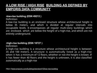
-low-rise building (ESN49213 )
Definition:
A low-rise building is an enclosed structure whose architectural height is
below 35 meters, and which is divided at regular intervals into
occupiable levels. It encompasses all regular multi-story buildings which
are enclosed, which are below the height of a high-rise, and which are not
entirely underground.
https://www.emporis.com/building/standard/15/low-rise-building
-high-rise building (ESN 18727 )
Definition:
A high-rise building is a structure whose architectural height is between
35 and 100 meters. A structure is automatically listed as a high-rise
when it has a minimum of 12 floors, whether or not the height is known. If
it has fewer than 40 floors and the height is unknown, it is also classified
automatically as a high-rise
A LOW RISE / HIGH RISE BUILDING AS DEFINED BY
EMPORIS DATA COMMUNITY
3.
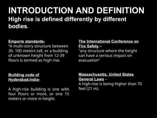
INTRODUCTION AND DEFINITION
Highrise is defined differently by different
bodies.
Emporis standards-
“A multi-story structure between
35- 100 meters tall, or a building
of unknown height from 12-39
floors is termed as high rise.
Building code of
Hyderabad,India-
A high-rise building is one with
four floors or more, or one 15
meters or more in height.
The International Conference on
Fire Safety –
"any structure where the height
can have a serious impact on
evacuation“
Massachusetts, United States
General Laws –
A high-rise is being higher than 70
feet (21 m).
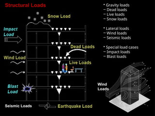
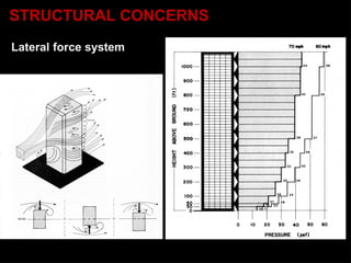
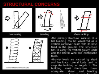
overturning bending shearracking
-The primary structural skeleton of a
tall building can be visualized as a
vertical cantilever beam with its base
fixed in the ground. The structure
has to carry the vertical gravity loads
and the lateral wind and earthquake
loads.
-Gravity loads are caused by dead
and live loads. Lateral loads tend to
snap the building or topple it. The
building must therefore have
adequate shear and bending
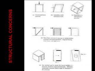
STRUCTURAL CONCERNS
12.
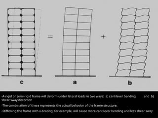
-A rigid orsemi-rigid frame will deform under lateral loads in two ways: a) cantilever bending and b)
shear sway distortion
-The combination of these represents the actual behavior of the frame structure.
-Stiffening the frame with x-bracing, for example, will cause more cantilever bending and less shear sway
13.
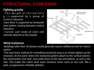
Fighting gravity
- Th e we i g ht o f t h e b u i l d i n
g i s supported by a group of
vertical coloumns
-Each floor is supported by horizontal
steel girders running between vertical
coloumns.
- Curtain wall made of steel and
concrete attaches to the outside
Wind resistance
-Buildings taller than 10 storeys would generally require additional steel for lateral
system.
-The most basic method for controlling horizontal sway is to simply tighten up the
structure. At the point where the horizontal girders attach to the vertical column,
the construction crew bolt: and welds them on the top and bottom. as well as the
side. This makes the entire steel super structure move more as one unit, like a
pole, as opposed to a flexible skeleton.
STRUCTURAL CONCERNS
14.
STRUCTURAL CONCERNS
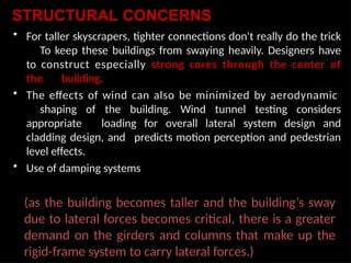
• Fortaller skyscrapers, tighter connections don't really do the trick
To keep these buildings from swaying heavily. Designers have
to construct especially strong cores through the center of
the building.
• The effects of wind can also be minimized by aerodynamic
shaping of the building. Wind tunnel testing considers
appropriate loading for overall lateral system design and
cladding design, and predicts motion perception and pedestrian
level effects.
• Use of damping systems
(as the building becomes taller and the building’s sway
due to lateral forces becomes critical, there is a greater
demand on the girders and columns that make up the
rigid-frame system to carry lateral forces.)
15.
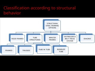
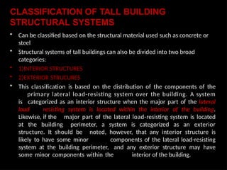
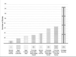
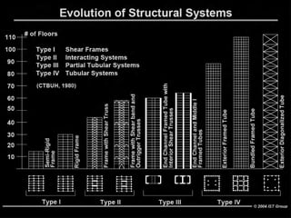
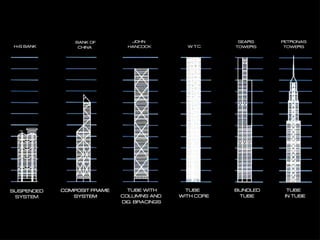
CLASSIFICATION OF TALLBUILDING
STRUCTURAL SYSTEMS
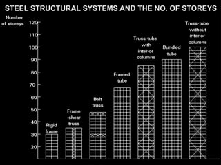
• Can be classified based on the structural material used such as concrete or
steel
• Structural systems of tall buildings can also be divided into two broad
categories:
• 1)INTERIOR STRUCTURES
• 2)EXTERIOR STRUCURES
• This classification is based on the distribution of the components of the
primary lateral load-resisting system over the building. A system
is categorized as an interior structure when the major part of the lateral
load resisting system is located within the interior of the building.
Likewise, if the major part of the lateral load-resisting system is located
at the building perimeter, a system is categorized as an exterior
structure. It should be noted, however, that any interior structure is
likely to have some minor components of the lateral load-resisting
system at the building perimeter, and any exterior structure may have
some minor components within the interior of the building.
16.
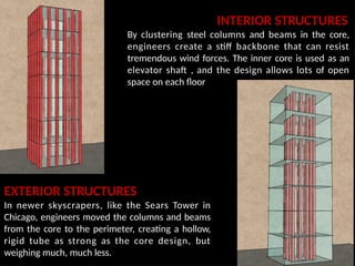
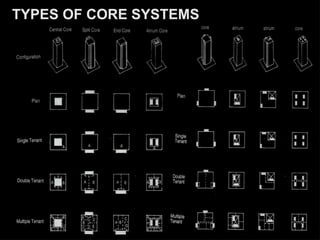
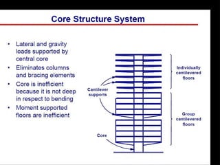
INTERIOR STRUCTURES
By clusteringsteel columns and beams in the core,
engineers create a stiff backbone that can resist
tremendous wind forces. The inner core is used as an
elevator shaft , and the design allows lots of open
space on each floor
EXTERIOR STRUCTURES
In newer skyscrapers, like the Sears Tower in
Chicago, engineers moved the columns and beams
from the core to the perimeter, creating a hollow,
rigid tube as strong as the core design, but
weighing much, much less.
17.
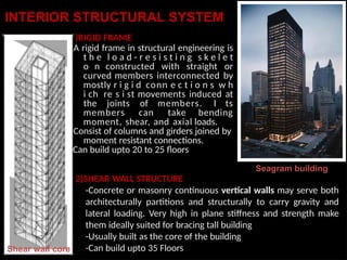
INTERIOR STRUCTURAL SYSTEM
1
-
-
-
Shearwall core
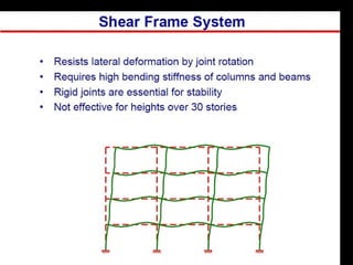
)RIGID FRAME
A rigid frame in structural engineering is
t h e l o a d - r e s i s t i n g s k e l e t
o n constructed with straight or
curved members interconnected by
mostly r i g i d conn e c t i o n s w h
i ch re s i st movements induced at
the joints of members. I ts
members can take bending
moment, shear, and axial loads.
Consist of columns and girders joined by
moment resistant connections.
Can build upto 20 to 25 floors
Seagram building
2)SHEAR WALL STRUCTURE
-Concrete or masonry continuous vertical walls may serve both
architecturally partitions and structurally to carry gravity and
lateral loading. Very high in plane stiffness and strength make
them ideally suited for bracing tall building
-Usually built as the core of the building
-Can build upto 35 Floors
18.
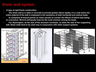
• A typeof rigid frame construction.
• The shear wall is in steel or concrete to provide greater lateral rigidity. It is a wall where the
entire material of the wall is employed in the resistance of both horizontal and vertical loads.
• Is composed of braced panels (or shear panels) to counter the effects of lateral load acting
on a structure. Wind & earthquake load are the most common among the loads.
• For skyscrapers, as the size of the structure increases, so does the size of the supporting
wall. Shear walls tend to be used only in conjunction with other support systems.
Shear wall system
19.
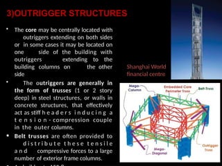
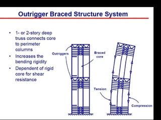
3)OUTRIGGER STRUCTURES
• Thecore may be centrally located with
outriggers extending on both sides
or in some cases it may be located on
one side of the building with
outriggers extending to the
building columns on the other
side
• The outriggers are generally in
the form of trusses (1 or 2 story
deep) in steel structures, or walls in
concrete structures, that effectively
act as stiff h e a d e r s i n d u c i n g a
t e n s i o n - compression couple
in the outer columns.
• Belt trusses are often provided to
d i s t r i b u t e t h e s e t e n s i l e
a n d compressive forces to a large
number of exterior frame columns.
Shanghai World
financial centre
21.
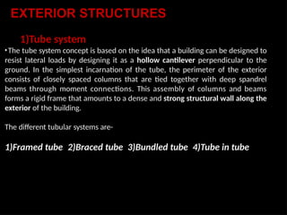
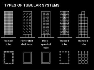
1)Tube system
•The tubesystem concept is based on the idea that a building can be designed to
resist lateral loads by designing it as a hollow cantilever perpendicular to the
ground. In the simplest incarnation of the tube, the perimeter of the exterior
consists of closely spaced columns that are tied together with deep spandrel
beams through moment connections. This assembly of columns and beams
forms a rigid frame that amounts to a dense and strong structural wall along the
exterior of the building.
The different tubular systems are-
1)Framed tube 2)Braced tube 3)Bundled tube 4)Tube in tube
EXTERIOR STRUCTURES
24.
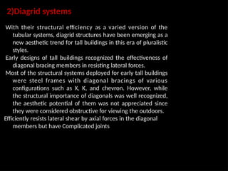
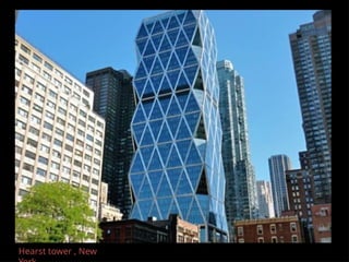
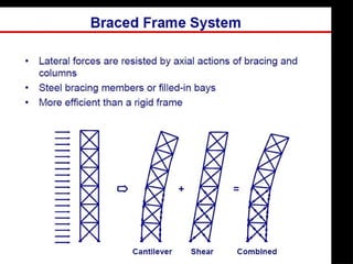
2)Diagrid systems
With theirstructural efficiency as a varied version of the
tubular systems, diagrid structures have been emerging as a
new aesthetic trend for tall buildings in this era of pluralistic
styles.
Early designs of tall buildings recognized the effectiveness of
diagonal bracing members in resisting lateral forces.
Most of the structural systems deployed for early tall buildings
were steel frames with diagonal bracings of various
configurations such as X, K, and chevron. However, while
the structural importance of diagonals was well recognized,
the aesthetic potential of them was not appreciated since
they were considered obstructive for viewing the outdoors.
Efficiently resists lateral shear by axial forces in the diagonal
members but have Complicated joints
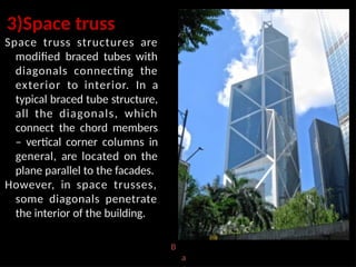
3)Space truss
Space trussstructures are
modified braced tubes with
diagonals connecting the
exterior to interior. In a
typical braced tube structure,
all the diagonals, which
connect the chord members
– vertical corner columns in
general, are located on the
plane parallel to the facades.
However, in space trusses,
some diagonals penetrate
the interior of the building.
B
a
27.
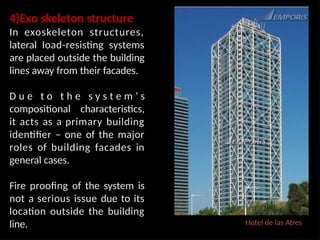
Hotel de lasAtres
4)Exo skeleton structure
In exoskeleton structures,
lateral load-resisting systems
are placed outside the building
lines away from their facades.
D u e t o t h e s y s t e m ’ s
compositional characteristics,
it acts as a primary building
identifier – one of the major
roles of building facades in
general cases.
Fire proofing of the system is
not a serious issue due to its
location outside the building
line.
28.
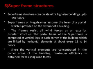
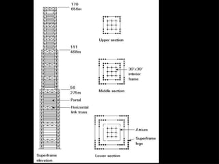
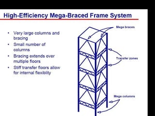
5)Super frame structures
•Superframe structures can create ultra high-rise buildings upto
160 floors.
• Superframes or Megaframes assume the form of a portal
which is provided on the exterior of a building.
• The frames resist all wind forces as an exterior
tubular structure. The portal frame of the Superframe is
composed of vertical legs in each corner of the building which
are linked by horizontal elements at about every 12 to 14
floors.
• Since the vertical elements are concentrated in the
corner areas of the building, maximum efficiency is
obtained for resisting wind forces.
31.
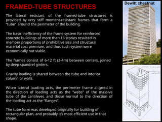
FRAMED-TUBE STRUCTURES
The lateralresistant of the framed-tube structures is
provided by very stiff moment-resistant frames that form a
“tube” around the perimeter of the building.
The basic inefficiency of the frame system for reinforced
concrete buildings of more than 15 stories resulted in
member proportions of prohibitive size and structural
material cost premium, and thus such system were
economically not viable.
The frames consist of 6-12 ft (2-4m) between centers, joined
by deep spandrel girders.
Gravity loading is shared between the tube and interior
column or walls.
When lateral loading acts, the perimeter frame aligned in
the direction of loading acts as the “webs” of the massive
tube of the cantilever, and those normal to the direction of
the loading act as the “flanges”.
The tube form was developed originally for building of
rectangular plan, and probably it’s most efficient use in that
shape.
32.
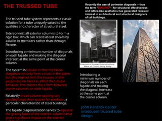
THE TRUSSED TUBE
Thetrussed tube system represents a classic
solution for a tube uniquely suited to the
qualities and character of structural steel.
Interconnect all exterior columns to form a
rigid box, which can resist lateral shears by
axial in its members rather than through
flexure.
Introducing a minimum number of diagonals
on each façade and making the diagonal
intersect at the same point at the corner
column.
The system is tubular in that the fascia
diagonals not only form a truss in the plane,
but also interact with the trusses on the
perpendicular faces to affect the tubular
behavior. This creates the x form between
corner columns on each façade.
Relatively broad column spacing can
resulted large clear spaces for windows, a
particular characteristic of steel buildings.
The façade diagonalization serves to equalize
the gravity loads of the exterior columns that
give a significant impact on the exterior
Recently the use of perimeter diagonals – thus
the term “DIAGRID” - for structural effectiveness
and lattice-like aesthetics has generated renewed
interest in architectural and structural designers
of tall buildings.
Introducing a
minimum number of
diagonals on each
façade and making
the diagonal intersect
at the same point at
the corner column
John Hancock Center
introduced trussed tube
design.
33.
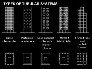
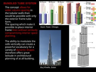
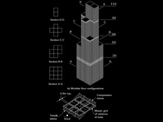
BUNDLED TUBE SYSTEM
Theconcept allows for
wider column spacing in
the tubular walls than
would be possible with only
the exterior frame tube
form.
The spacing which make it
possible to place interior
frame lines without seriously
compromising interior space
planning.
The ability to modulate the
cells vertically can create a
powerful vocabulary for a
variety of dynamic shapes
therefore offers great
latitude in architectural
planning of at all building.
Burj Khalifa, Dubai.
Sears Tower, Chicago.
34.
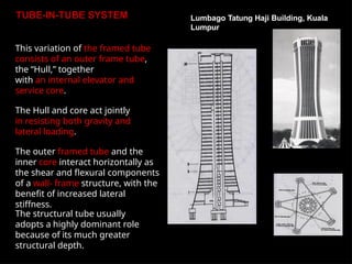
TUBE-IN-TUBE SYSTEM
This variationof the framed tube
consists of an outer frame tube,
the “Hull,” together
with an internal elevator and
service core.
The Hull and core act jointly
in resisting both gravity and
lateral loading.
The outer framed tube and the
inner core interact horizontally as
the shear and flexural components
of a wall- frame structure, with the
benefit of increased lateral
stiffness.
The structural tube usually
adopts a highly dominant role
because of its much greater
structural depth.
Lumbago Tatung Haji Building, Kuala
Lumpur
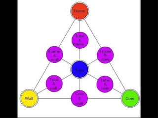
45.
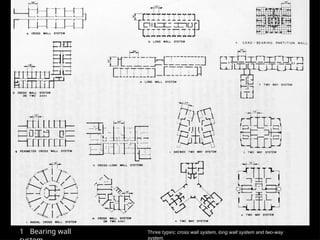
1 Bearing wallThree types: cross wall system, long wall system and two-way
system.
46.
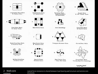
2 Wall-core Lateralforce resistance is shared between load bearing wall structure and service core
structures.
47.
2 Wall-core Lateralforce resistance is shared between load bearing wall structure and service core
structures.
48.
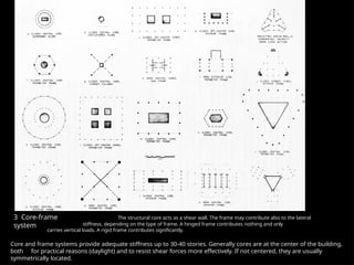
3 Core-frame
system
The structuralcore acts as a shear wall. The frame may contribute also to the lateral
stiffness, depending on the type of frame. A hinged frame contributes nothing and only
carries vertical loads. A rigid frame contributes significantly.
Core and frame systems provide adequate stiffness up to 30-40 stories. Generally cores are at the center of the building,
both for practical reasons (daylight) and to resist shear forces more effectively. If not centered, they are usually
symmetrically located.
49.
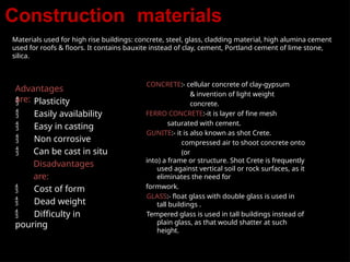
Construction materials
Materials usedfor high rise buildings: concrete, steel, glass, cladding material, high alumina cement
used for roofs & floors. It contains bauxite instead of clay, cement, Portland cement of lime stone,
silica.
Advantages
are:
Plasticity
Easily availability
Easy in casting
Non corrosive
Can be cast in situ
Disadvantages
are:
Cost of form
Dead weight
Difficulty in
pouring
CONCRETE:- cellular concrete of clay-gypsum
& invention of light weight
concrete.
FERRO CONCRETE:-it is layer of fine mesh
saturated with cement.
GUNITE:- it is also known as shot Crete.
compressed air to shoot concrete onto
(or
into) a frame or structure. Shot Crete is frequently
used against vertical soil or rock surfaces, as it
eliminates the need for
formwork.
GLASS:- float glass with double glass is used in
tall buildings .
Tempered glass is used in tall buildings instead of
plain glass, as that would shatter at such
height.
50.
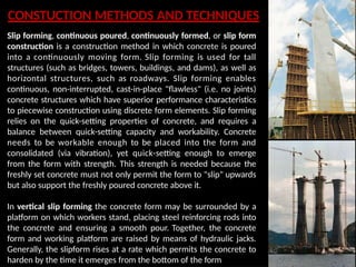
CONSTUCTION METHODS ANDTECHNIQUES
Slip forming, continuous poured, continuously formed, or slip form
construction is a construction method in which concrete is poured
into a continuously moving form. Slip forming is used for tall
structures (such as bridges, towers, buildings, and dams), as well as
horizontal structures, such as roadways. Slip forming enables
continuous, non-interrupted, cast-in-place "flawless" (i.e. no joints)
concrete structures which have superior performance characteristics
to piecewise construction using discrete form elements. Slip forming
relies on the quick-setting properties of concrete, and requires a
balance between quick-setting capacity and workability. Concrete
needs to be workable enough to be placed into the form and
consolidated (via vibration), yet quick-setting enough to emerge
from the form with strength. This strength is needed because the
freshly set concrete must not only permit the form to "slip" upwards
but also support the freshly poured concrete above it.
In vertical slip forming the concrete form may be surrounded by a
platform on which workers stand, placing steel reinforcing rods into
the concrete and ensuring a smooth pour. Together, the concrete
form and working platform are raised by means of hydraulic jacks.
Generally, the slipform rises at a rate which permits the concrete to
harden by the time it emerges from the bottom of the form
51.
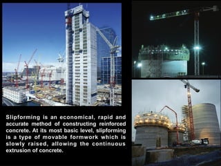
Slipforming is aneconomical, rapid and
accurate method of constructing reinforced
concrete. At its most basic level, slipforming
is a type of movable formwork which is
slowly raised, allowing the continuous
extrusion of concrete.
52.
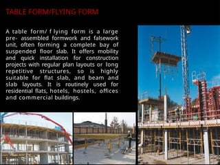
A table form/f lying form is a large
pre- assembled formwork and falsework
unit, often forming a complete bay of
suspended floor slab. It offers mobility
and quick installation for construction
projects with regular plan layouts or long
repetitive structures, so is highly
suitable for flat slab, and beam and
slab layouts. It is routinely used for
residential flats, hotels, hostels, offices
and commercial buildings.
TABLE FORM/FLYING FORM
53.
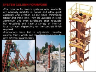
SYSTEM COLUMN FORMWORK
-Thecolumn formwork systems now available
are normally modular in nature and allow quick
assembly and erection on-site while minimising
labour and crane time. They are available in steel,
aluminium and even cardboard (not reusable
but recycled) and have a variety of internal
face surfaces depending on the concrete finish
required.
-Innovations have led to adjustable, reusable
column forms which can be clamped on-site to
give different column sizes.
54.
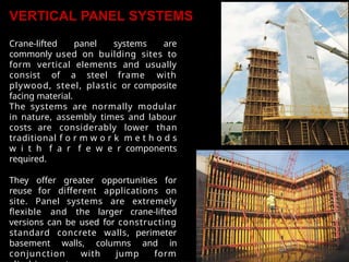
VERTICAL PANEL SYSTEMS
Crane-liftedpanel systems are
commonly used on building sites to
form vertical elements and usually
consist of a steel frame with
plywood, steel, plastic or composite
facing material.
The systems are normally modular
in nature, assembly times and labour
costs are considerably lower than
traditional f o r m w o r k m e t h o d s
w i t h f a r f e w e r components
required.
They offer greater opportunities for
reuse for different applications on
site. Panel systems are extremely
flexible and the larger crane-lifted
versions can be used for constructing
standard concrete walls, perimeter
basement walls, columns and in
conjunction with jump form
55.
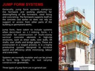
JUMP FORM SYSTEMS
Generally,jump form systems comprise
the formwork and working platforms for
cleaning/fixing of the formwork, steel fixing
and concreting. The formwork supports itself on
the concrete cast earlier so does not rely on
support or access from other parts of the
building or permanent works.
Jump form, here taken to include systems
often described as c l imbing form, i s
suitable for construction of multi-storey
vertical concrete elements in high-rise
structures, such as shear walls, core walls, lift
shafts, stair shafts and bridge pylons. These are
constructed in a staged process. It is a highly
productive system designed to increase
speed and efficiency while minimising labour
and crane time.
Systems are normally modular and can be joined
to form long lengths to suit varying
construction geometries.
Three types of jump form are in general use:
56.
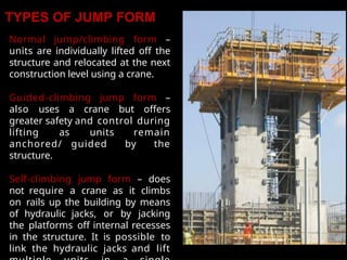
TYPES OF JUMPFORM
Normal jump/climbing form –
units are individually lifted off the
structure and relocated at the next
construction level using a crane.
Guided-climbing jump form –
also uses a crane but offers
greater safety and control during
lifting as units remain
anchored/ guided by the
structure.
Self-climbing jump form – does
not require a crane as it climbs
on rails up the building by means
of hydraulic jacks, or by jacking
the platforms off internal recesses
in the structure. It is possible to
link the hydraulic jacks and lift
57.
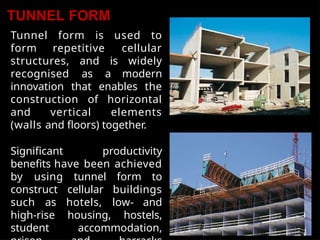
TUNNEL FORM
Tunnel formis used to
form repetitive cellular
structures, and is widely
recognised as a modern
innovation that enables the
construction of horizontal
and vertical elements
(walls and floors) together.
Significant productivity
benefits have been achieved
by using tunnel form to
construct cellular buildings
such as hotels, low- and
high-rise housing, hostels,
student accommodation,