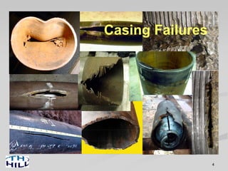
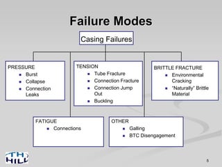
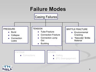
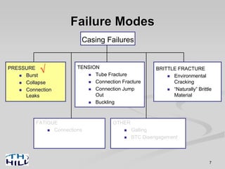
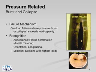
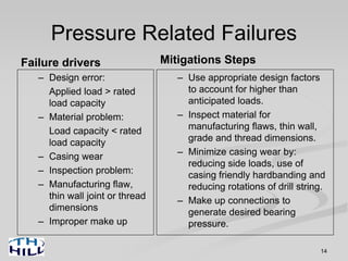
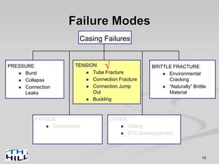
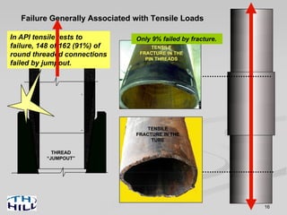
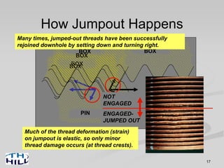
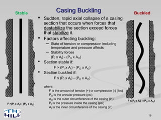
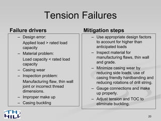
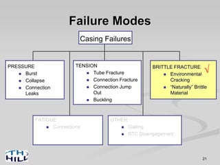
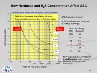
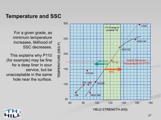
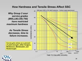
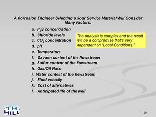
Casing Failure Prevention
East Texas Gas Producer’s Assoc.
9 March 2010
2
The Ideal Casing String
• For as long as needed, it will:
– Safely carry all applied loads,
– and be free from leaks.
Until the next string is set…
…to the life of the well
3
Three Steps are Required to
Achieve the Ideal…
• Design: The engineer decides casing sizes,
weights, grades and connections for each hole
section (usually choosing from available ‘standard’
options).
• Manufacturing and Procurement: Someone builds
the casing (and coupling stock), someone threads the
connections, someone buys the casing and someone
delivers it to the rig.
• Installation: Rig crew and casing crew pick it up one
joint at a time and run it.
A breakdown in any one of these
steps can result in a casing failure!
Design
Manufacturing
Installation
The discussion today will focus
on:
•Common failure modes
•Underlying causes
•Steps to minimize the risk of failure
4
Casing Failures
Failure Modes
Casing Failures
PRESSURE
Burst
Collapse
Connection
Leaks
TENSION
Tube Fracture
Connection Fracture
Connection Jump
Out
Buckling
BRITTLE FRACTURE
Environmental
Cracking
“Naturally” Brittle
Material
FATIGUE
Connections
OTHER
Galling
BTC Disengagement
5
Failure Modes
Casing Failures
PRESSURE
Burst
Collapse
Connection
Leaks
TENSION
Tube Fracture
Connection Fracture
Connection Jump
Out
Buckling
BRITTLE FRACTURE
Environmental
Cracking
“Naturally” Brittle
Material
FATIGUE
Connections
OTHER
Galling
BTC Disengagement
6
Failure Modes
Casing Failures
PRESSURE
Burst
Collapse
Connection
Leaks
TENSION
Tube Fracture
Connection Fracture
Connection Jump
Out
Buckling
BRITTLE FRACTURE
Environmental
Cracking
“Naturally” Brittle
Material
FATIGUE
Connections
OTHER
Galling
BTC Disengagement
√
7
Pressure Related
Burst and Collapse
• Failure Mechanism
Overload failures where pressure (burst
or collapse) exceeds load capacity
• Recognition
– Appearance: Plastic deformation
(ductile material)
– Orientation: Longitudinal
– Location: Sections with highest loads
8
BURST FAILURE
COLLAPSE FAILURE
9
Axial and Pressure Loads Interactively Affect One Another
-2000
2000
4000
6000
8000
10000
-700 -600 -500 -400 -300 -200 -100 100 200
Triaxial Ellipse
for 7"- 23.0 lb/ft
N-80 Casing
BurstStrength(psi)CollapseStrength(psi)
(1000 lbf)
Compression Tension
500300 400 600 700
-8000
-10000
-6000
-4000
Axial Force
-2000
2000
4000
6000
-500 -400 -300 -200 -100 100 200
Compression Tension
500300 400
-8000
-6000
-4000
Remember…..
Pressure and Tension are not independent.
Connections
10
Internal Pressure (PI)Internal Pressure (PI)
Why Connections Leak:
1. Inadequate Bearing Pressure
Bearing Pressure (PB)
If bearing pressure (PB) exceeds
internal pressure (PI), then no leak.
If internal pressure (PI) exceeds bearing
pressure (PB), then leak.
Connections
11
Bearing Pressure (PB)
Why Connections Leak:
2. Leak Path Across Seal(s)
A leak path is present on this pin seal. The seal
will leak regardless of how much bearing
pressure is forcing the two components
together.
Connections
12
API Connections Have Built-In (Helical) Leak Paths
These tortuous paths are plugged with the
solids in thread dope during makeup.
API ROUND THREAD
PIN
BOX
API BUTTRESS
PIN
BOX
Connections
13
Preventing Leaks
• Leak Paths (other than helical)
• Inadequate Bearing
Pressure
Adequate Bearing Pressure is assured by:
--Proper dimensions
--Proper makeup
Found in visual inspection. Removed
from the string.
Pressure Related Failures
Failure drivers
– Design error:
Applied load > rated
load capacity
– Material problem:
Load capacity < rated
load capacity
– Casing wear
– Inspection problem:
– Manufacturing flaw,
thin wall joint or thread
dimensions
– Improper make up
Mitigations Steps
– Use appropriate design factors
to account for higher than
anticipated loads.
– Inspect material for
manufacturing flaws, thin wall,
grade and thread dimensions.
– Minimize casing wear by:
reducing side loads, use of
casing friendly hardbanding and
reducing rotations of drill string.
– Make up connections to
generate desired bearing
pressure.
14
Failure Modes
Casing Failures
PRESSURE
Burst
Collapse
Connection
Leaks
TENSION
Tube Fracture
Connection Fracture
Connection Jump
Out
Buckling
BRITTLE FRACTURE
Environmental
Cracking
“Naturally” Brittle
Material
FATIGUE
Connections
OTHER
Galling
BTC Disengagement
√
15
16
Failure Generally Associated with Tensile Loads
TENSILE
FRACTURE IN THE
TUBE
TENSILE
FRACTURE IN THE
PIN THREADS
THREAD
“JUMPOUT”
In API tensile tests to
failure, 148 of 162 (91%) of
round threaded connections
failed by jumpout.
Only 9% failed by fracture.
17
BOX
PIN
How Jumpout Happens
BOX
BOX
BOX BOX
NOT
ENGAGED
ENGAGED-
JUMPED OUT
Much of the thread deformation (strain)
on jumpout is elastic, so only minor
thread damage occurs (at thread crests).
Many times, jumped-out threads have been successfully
rejoined downhole by setting down and turning right.
18
Jumpout - The Main Reason API Adopted
the Buttress Thread Form
BOX
PIN
API BUTTRESS THREAD FORM
3 degrees
Vs. 30 degrees for the
round thread form
19
Casing Buckling
• Sudden, rapid axial collapse of a casing
section that occurs when forces that
destabilize the section exceed forces
that stabilize it.
• Factors affecting buckling:
– State of tension or compression including
temperature and pressure affects
– Stability forces
(PI x AI) - (PO x AO)
• Section stable if:
F > (PI x AI) - (PO x AO)
• Section buckled if:
F ≤ (PI x AI) - (PO x AO)
where:
F is the amount of tension (+) or compression (-) (lbs)
PO is the annular pressure (psi)
AO is the outer circumference of the casing (in)
PI is the pressure inside the casing (psi)
AI is the inner circumference of the casing (in)
F ≤(PI x AI) - (PO x AO)
Buckled
F >(PI x AI) - (PO x AO)
Stable
Tension Failures
Failure drivers
– Design error:
Applied load > rated load
capacity
– Material problem:
Load capacity < rated load
capacity
– Casing wear
– Inspection problem:
Manufacturing flaw, thin wall
joint or incorrect thread
dimensions.
– Improper make up
– Casing buckling
Mitigation steps
– Use appropriate design factors
to account for higher than
anticipated loads
– Inspect material for
manufacturing flaws, thin wall
and grade.
– Minimize casing wear by
reducing side loads, use of
casing friendly hardbanding and
reducing rotations of drill string.
– Gauge connections and make
up properly.
– Adjust tension and TOC to
eliminate buckling.
20
Failure Modes
Casing Failures
PRESSURE
Burst
Collapse
Connection
Leaks
TENSION
Tube Fracture
Connection Fracture
Connection Jump
Out
Buckling
BRITTLE FRACTURE
Environmental
Cracking
“Naturally” Brittle
Material
FATIGUE
Connections
OTHER
Galling
BTC Disengagement
√
21
22
BRITTLE FRACTURE (Hydrogen Induced)
This brittle coupling fracture occurred in
an H2S (hydrogen sulfide) environment.
The mechanism is called Sulfide Stress
Cracking (SSC)
Whether or not such a failure will happen
depends on many factors that work
together in complex interrelationships:
H2S concentration
Time of exposure
Tensile stress level
Metallurgical properties
Temperature
Other factors
Microscopically, Sulfide Stress
cracks tend to be branched
and run along grain
boundaries.
Free hydrogen ions from the chemical reaction with H2S
entered the steel in this coupling and made it brittle, leading to
the failure. But some materials begin life brittle…
23
BRITTLE FRACTURE
(“Naturally” Induced)
This N80 casing joint was never
exposed to hydrogen sulfide.
Rather, it came brittle off the
production line due to improper
metallurgy and/or heat treatment.
Under impact loading, the pipe
cracked and parted (much like
laboratory glass piping is cut)
when a crack started at the
bottom of a slip cut, and rapid,
brittle fracture occurred. Such
a material is called “NOTCH-
SENSITIVE.”
Slip cuts
24
SAFE
Why Tough Material is Better Than Brittle
MATERIAL “A” - BRITTLE, NOTCH-SENSITIVE
MATERIAL “B” - TOUGH
Will fail by tearing
apart like a piece
of taffy, not
shattering like a
piece of glass!
DEFECT SIZE
TENSILESTRESS
RAPID,
BRITTLE
FRACTURE
MATERIAL “A”
MATERIAL “B”
Can safely carry a larger defect at a given stress…
Can safely
carry a higher
stress with a
given defect,
Tougher materials are safer & more “forgiving”
In impact loading
In fatigue loading
In hydrogen sulfide
25
Fundamentals of Casing Material Selection for
Sour and Corrosive Service
Fundamentals!
Recall the failure mechanism
Sulfide Stress Cracking (SSC)
Free hydrogen generated in the
H2S-Steel corrosion reaction
causes otherwise ductile metal to
become brittle and crack.
26
Curves give H2S concentration
in NaCl solution. (After Hudgins,
McGlasson, Mehdizadeh, and
Rosborough)
How Hardness and H2S Concentration Affect SSC
(5% NaCl solutrion. Carbon steel specimens @ 130% yield stress)
H2S
PPM
8000
3000
15
5
1
0.1
H2S PP @
10,000 psi
80
30
0.15
.05
.01
.001
NACE definition of “sour:”
H2S Partial Pressure ≥ 0.05 psia.
(5 PPM @ 10,000 psi)
10
15
20
25
30
35
40
0.1 1 10 100 1000 104
HARDNESS(HRC)
TIME TO FAILURE (HOURS)
DAY WEEK MONTH YEAR
0.1 ppm
1.0 ppm
15
3000
8000
90
minutes
Six
months
As hardness decreases, time to failure increases.
As concentration decreases, time to failure increases.
27
NO SSC
SSC
Temperature and SSC
For a given grade, as
minimum temperature
increases, liklihood of
SSC decreases.
This explains why P110
(for example) may be fine
for a deep liner in sour
service, but be
unacceptable in the same
hole near the surface.
P110 range of
possible YS
NACE Minimum
Temperature for P110
28
Curves give stress as a percent
of yield strength. (After Hudgins,
McGlasson, Mehdizadeh, and
Rosborough)
How Hardness and Tensile Stress Affect SSC
(300 ppm H2S in 5% NaCl solutrion. Carbon steel specimens)
As Tensile Stress
decreases, time to
failure increases.
15
20
25
30
35
40
45
0.1 1 10 100 1000
HARDNESS(HRC)
TIME TO FAILURE (HOURS)
DAY MONTHWEEK
40%
130%
100%
80%
60%
Why Group 2 sour
service grades
(M65,L80,C90,T95)
have restricted
maximum hardness
29
A Corrosion Engineer Selecting a Sour Service Material Will Consider
Many Factors:
a. H2S concentration
b. Chloride levels
c. CO2 concentration
d. pH
e. Temperature
f. Oxygen content of the flowstream
g. Sulfur content of the flowstream
h. Gas/Oil Ratio
i. Water content of the flowstream
j. Fluid velocity
k. Cost of alternatives
l. Anticipated life of the well
The analysis is complex and the result
will be a compromise that’s very
dependent on “Local Conditions.”
30
Typical Chemistry of Steels
Classification
Carbon
Steels
Low Alloy
Steels
Stainless
Steels
Nickel Based
Alloys
Element (% Wt.)
Carbon 0.3 - 0.5 0.3 - 0.5 <0.25 <0.3
Manganese 0.5 - 2.0 <2 <2 <2
Molybdenum ---- <1 <4 <10
Chromium ---- <2 9 - 26 <25
Nickel ---- <1 <25 40 - 70
Iron >97 >95 40 - 85 2 - 40
Typical Cost Ratios
1 1.5 3 - 10 $$$!
31
400
300
275
475
0.15 1.5 10 1000 10000
200
800
1500
2000
NIC 62
(C-276)
NIC 42
(G3, SM2550)
22 CR, 25 CR
(DUPLEX SS)
13 CR
(420 MOD SS)
9 Cr
Partial Pressure H2S (psia)
Temperature(degF)
400 deg F
300 deg F
A Guide for the Application of Corrosion Resistant Alloys (CRA)
$1.5-2
$2-3
$6-7
$12-14
$16-20
If L80 Type 1 costs $1
Not for Material Selection!
(talk to your corrosion engineer)
Prices will vary widely with
conditions in the metal markets.
Higher temperature
benefits SSC, but
accelerates weight-
loss corrosion.
Questions
32

TH. hill casing failures training course Presentation 2010

  • 1.
    Casing Failure Prevention EastTexas Gas Producer’s Assoc. 9 March 2010
  • 2.
    2 The Ideal CasingString • For as long as needed, it will: – Safely carry all applied loads, – and be free from leaks. Until the next string is set… …to the life of the well
  • 3.
    3 Three Steps areRequired to Achieve the Ideal… • Design: The engineer decides casing sizes, weights, grades and connections for each hole section (usually choosing from available ‘standard’ options). • Manufacturing and Procurement: Someone builds the casing (and coupling stock), someone threads the connections, someone buys the casing and someone delivers it to the rig. • Installation: Rig crew and casing crew pick it up one joint at a time and run it. A breakdown in any one of these steps can result in a casing failure! Design Manufacturing Installation The discussion today will focus on: •Common failure modes •Underlying causes •Steps to minimize the risk of failure
  • 4.
  • 5.
    Failure Modes Casing Failures PRESSURE Burst Collapse Connection Leaks TENSION TubeFracture Connection Fracture Connection Jump Out Buckling BRITTLE FRACTURE Environmental Cracking “Naturally” Brittle Material FATIGUE Connections OTHER Galling BTC Disengagement 5
  • 6.
    Failure Modes Casing Failures PRESSURE Burst Collapse Connection Leaks TENSION TubeFracture Connection Fracture Connection Jump Out Buckling BRITTLE FRACTURE Environmental Cracking “Naturally” Brittle Material FATIGUE Connections OTHER Galling BTC Disengagement 6
  • 7.
    Failure Modes Casing Failures PRESSURE Burst Collapse Connection Leaks TENSION TubeFracture Connection Fracture Connection Jump Out Buckling BRITTLE FRACTURE Environmental Cracking “Naturally” Brittle Material FATIGUE Connections OTHER Galling BTC Disengagement √ 7
  • 8.
    Pressure Related Burst andCollapse • Failure Mechanism Overload failures where pressure (burst or collapse) exceeds load capacity • Recognition – Appearance: Plastic deformation (ductile material) – Orientation: Longitudinal – Location: Sections with highest loads 8 BURST FAILURE COLLAPSE FAILURE
  • 9.
    9 Axial and PressureLoads Interactively Affect One Another -2000 2000 4000 6000 8000 10000 -700 -600 -500 -400 -300 -200 -100 100 200 Triaxial Ellipse for 7"- 23.0 lb/ft N-80 Casing BurstStrength(psi)CollapseStrength(psi) (1000 lbf) Compression Tension 500300 400 600 700 -8000 -10000 -6000 -4000 Axial Force -2000 2000 4000 6000 -500 -400 -300 -200 -100 100 200 Compression Tension 500300 400 -8000 -6000 -4000 Remember….. Pressure and Tension are not independent.
  • 10.
    Connections 10 Internal Pressure (PI)InternalPressure (PI) Why Connections Leak: 1. Inadequate Bearing Pressure Bearing Pressure (PB) If bearing pressure (PB) exceeds internal pressure (PI), then no leak. If internal pressure (PI) exceeds bearing pressure (PB), then leak.
  • 11.
    Connections 11 Bearing Pressure (PB) WhyConnections Leak: 2. Leak Path Across Seal(s) A leak path is present on this pin seal. The seal will leak regardless of how much bearing pressure is forcing the two components together.
  • 12.
    Connections 12 API Connections HaveBuilt-In (Helical) Leak Paths These tortuous paths are plugged with the solids in thread dope during makeup. API ROUND THREAD PIN BOX API BUTTRESS PIN BOX
  • 13.
    Connections 13 Preventing Leaks • LeakPaths (other than helical) • Inadequate Bearing Pressure Adequate Bearing Pressure is assured by: --Proper dimensions --Proper makeup Found in visual inspection. Removed from the string.
  • 14.
    Pressure Related Failures Failuredrivers – Design error: Applied load > rated load capacity – Material problem: Load capacity < rated load capacity – Casing wear – Inspection problem: – Manufacturing flaw, thin wall joint or thread dimensions – Improper make up Mitigations Steps – Use appropriate design factors to account for higher than anticipated loads. – Inspect material for manufacturing flaws, thin wall, grade and thread dimensions. – Minimize casing wear by: reducing side loads, use of casing friendly hardbanding and reducing rotations of drill string. – Make up connections to generate desired bearing pressure. 14
  • 15.
    Failure Modes Casing Failures PRESSURE Burst Collapse Connection Leaks TENSION TubeFracture Connection Fracture Connection Jump Out Buckling BRITTLE FRACTURE Environmental Cracking “Naturally” Brittle Material FATIGUE Connections OTHER Galling BTC Disengagement √ 15
  • 16.
    16 Failure Generally Associatedwith Tensile Loads TENSILE FRACTURE IN THE TUBE TENSILE FRACTURE IN THE PIN THREADS THREAD “JUMPOUT” In API tensile tests to failure, 148 of 162 (91%) of round threaded connections failed by jumpout. Only 9% failed by fracture.
  • 17.
    17 BOX PIN How Jumpout Happens BOX BOX BOXBOX NOT ENGAGED ENGAGED- JUMPED OUT Much of the thread deformation (strain) on jumpout is elastic, so only minor thread damage occurs (at thread crests). Many times, jumped-out threads have been successfully rejoined downhole by setting down and turning right.
  • 18.
    18 Jumpout - TheMain Reason API Adopted the Buttress Thread Form BOX PIN API BUTTRESS THREAD FORM 3 degrees Vs. 30 degrees for the round thread form
  • 19.
    19 Casing Buckling • Sudden,rapid axial collapse of a casing section that occurs when forces that destabilize the section exceed forces that stabilize it. • Factors affecting buckling: – State of tension or compression including temperature and pressure affects – Stability forces (PI x AI) - (PO x AO) • Section stable if: F > (PI x AI) - (PO x AO) • Section buckled if: F ≤ (PI x AI) - (PO x AO) where: F is the amount of tension (+) or compression (-) (lbs) PO is the annular pressure (psi) AO is the outer circumference of the casing (in) PI is the pressure inside the casing (psi) AI is the inner circumference of the casing (in) F ≤(PI x AI) - (PO x AO) Buckled F >(PI x AI) - (PO x AO) Stable
  • 20.
    Tension Failures Failure drivers –Design error: Applied load > rated load capacity – Material problem: Load capacity < rated load capacity – Casing wear – Inspection problem: Manufacturing flaw, thin wall joint or incorrect thread dimensions. – Improper make up – Casing buckling Mitigation steps – Use appropriate design factors to account for higher than anticipated loads – Inspect material for manufacturing flaws, thin wall and grade. – Minimize casing wear by reducing side loads, use of casing friendly hardbanding and reducing rotations of drill string. – Gauge connections and make up properly. – Adjust tension and TOC to eliminate buckling. 20
  • 21.
    Failure Modes Casing Failures PRESSURE Burst Collapse Connection Leaks TENSION TubeFracture Connection Fracture Connection Jump Out Buckling BRITTLE FRACTURE Environmental Cracking “Naturally” Brittle Material FATIGUE Connections OTHER Galling BTC Disengagement √ 21
  • 22.
    22 BRITTLE FRACTURE (HydrogenInduced) This brittle coupling fracture occurred in an H2S (hydrogen sulfide) environment. The mechanism is called Sulfide Stress Cracking (SSC) Whether or not such a failure will happen depends on many factors that work together in complex interrelationships: H2S concentration Time of exposure Tensile stress level Metallurgical properties Temperature Other factors Microscopically, Sulfide Stress cracks tend to be branched and run along grain boundaries. Free hydrogen ions from the chemical reaction with H2S entered the steel in this coupling and made it brittle, leading to the failure. But some materials begin life brittle…
  • 23.
    23 BRITTLE FRACTURE (“Naturally” Induced) ThisN80 casing joint was never exposed to hydrogen sulfide. Rather, it came brittle off the production line due to improper metallurgy and/or heat treatment. Under impact loading, the pipe cracked and parted (much like laboratory glass piping is cut) when a crack started at the bottom of a slip cut, and rapid, brittle fracture occurred. Such a material is called “NOTCH- SENSITIVE.” Slip cuts
  • 24.
    24 SAFE Why Tough Materialis Better Than Brittle MATERIAL “A” - BRITTLE, NOTCH-SENSITIVE MATERIAL “B” - TOUGH Will fail by tearing apart like a piece of taffy, not shattering like a piece of glass! DEFECT SIZE TENSILESTRESS RAPID, BRITTLE FRACTURE MATERIAL “A” MATERIAL “B” Can safely carry a larger defect at a given stress… Can safely carry a higher stress with a given defect, Tougher materials are safer & more “forgiving” In impact loading In fatigue loading In hydrogen sulfide
  • 25.
    25 Fundamentals of CasingMaterial Selection for Sour and Corrosive Service Fundamentals! Recall the failure mechanism Sulfide Stress Cracking (SSC) Free hydrogen generated in the H2S-Steel corrosion reaction causes otherwise ductile metal to become brittle and crack.
  • 26.
    26 Curves give H2Sconcentration in NaCl solution. (After Hudgins, McGlasson, Mehdizadeh, and Rosborough) How Hardness and H2S Concentration Affect SSC (5% NaCl solutrion. Carbon steel specimens @ 130% yield stress) H2S PPM 8000 3000 15 5 1 0.1 H2S PP @ 10,000 psi 80 30 0.15 .05 .01 .001 NACE definition of “sour:” H2S Partial Pressure ≥ 0.05 psia. (5 PPM @ 10,000 psi) 10 15 20 25 30 35 40 0.1 1 10 100 1000 104 HARDNESS(HRC) TIME TO FAILURE (HOURS) DAY WEEK MONTH YEAR 0.1 ppm 1.0 ppm 15 3000 8000 90 minutes Six months As hardness decreases, time to failure increases. As concentration decreases, time to failure increases.
  • 27.
    27 NO SSC SSC Temperature andSSC For a given grade, as minimum temperature increases, liklihood of SSC decreases. This explains why P110 (for example) may be fine for a deep liner in sour service, but be unacceptable in the same hole near the surface. P110 range of possible YS NACE Minimum Temperature for P110
  • 28.
    28 Curves give stressas a percent of yield strength. (After Hudgins, McGlasson, Mehdizadeh, and Rosborough) How Hardness and Tensile Stress Affect SSC (300 ppm H2S in 5% NaCl solutrion. Carbon steel specimens) As Tensile Stress decreases, time to failure increases. 15 20 25 30 35 40 45 0.1 1 10 100 1000 HARDNESS(HRC) TIME TO FAILURE (HOURS) DAY MONTHWEEK 40% 130% 100% 80% 60% Why Group 2 sour service grades (M65,L80,C90,T95) have restricted maximum hardness
  • 29.
    29 A Corrosion EngineerSelecting a Sour Service Material Will Consider Many Factors: a. H2S concentration b. Chloride levels c. CO2 concentration d. pH e. Temperature f. Oxygen content of the flowstream g. Sulfur content of the flowstream h. Gas/Oil Ratio i. Water content of the flowstream j. Fluid velocity k. Cost of alternatives l. Anticipated life of the well The analysis is complex and the result will be a compromise that’s very dependent on “Local Conditions.”
  • 30.
    30 Typical Chemistry ofSteels Classification Carbon Steels Low Alloy Steels Stainless Steels Nickel Based Alloys Element (% Wt.) Carbon 0.3 - 0.5 0.3 - 0.5 <0.25 <0.3 Manganese 0.5 - 2.0 <2 <2 <2 Molybdenum ---- <1 <4 <10 Chromium ---- <2 9 - 26 <25 Nickel ---- <1 <25 40 - 70 Iron >97 >95 40 - 85 2 - 40 Typical Cost Ratios 1 1.5 3 - 10 $$$!
  • 31.
    31 400 300 275 475 0.15 1.5 101000 10000 200 800 1500 2000 NIC 62 (C-276) NIC 42 (G3, SM2550) 22 CR, 25 CR (DUPLEX SS) 13 CR (420 MOD SS) 9 Cr Partial Pressure H2S (psia) Temperature(degF) 400 deg F 300 deg F A Guide for the Application of Corrosion Resistant Alloys (CRA) $1.5-2 $2-3 $6-7 $12-14 $16-20 If L80 Type 1 costs $1 Not for Material Selection! (talk to your corrosion engineer) Prices will vary widely with conditions in the metal markets. Higher temperature benefits SSC, but accelerates weight- loss corrosion.
  • 32.