COMPLETING THE WELL
General
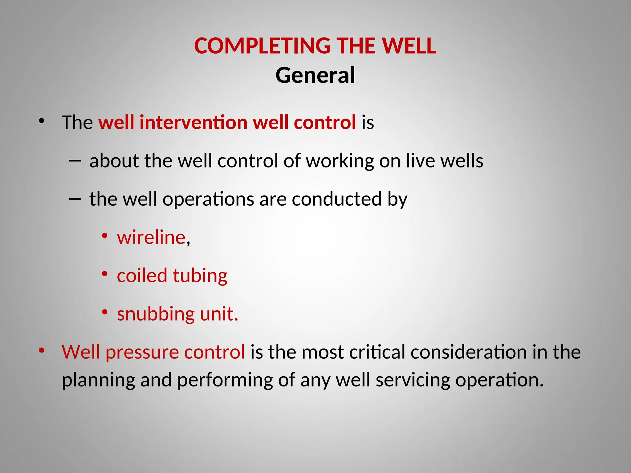
•The well intervention well control is
– about the well control of working on live wells
– the well operations are conducted by
• wireline,
• coiled tubing
• snubbing unit.
• Well pressure control is the most critical consideration in the
planning and performing of any well servicing operation.
3.
Completion Fluid Characteristics
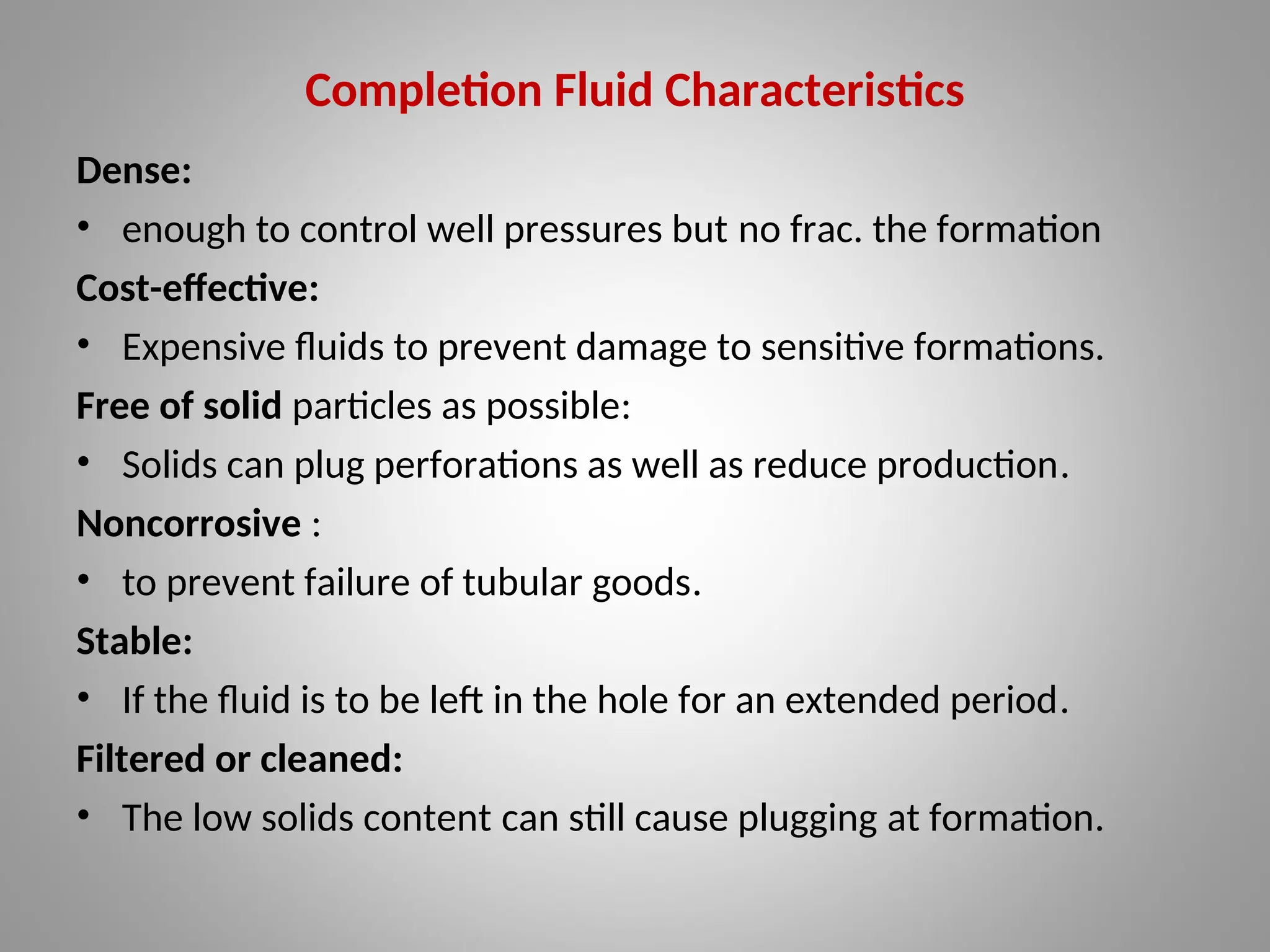
Dense:
•enough to control well pressures but no frac. the formation
Cost-effective:
• Expensive fluids to prevent damage to sensitive formations.
Free of solid particles as possible:
• Solids can plug perforations as well as reduce production.
Noncorrosive :
• to prevent failure of tubular goods.
Stable:
• If the fluid is to be left in the hole for an extended period.
Filtered or cleaned:
• The low solids content can still cause plugging at formation.
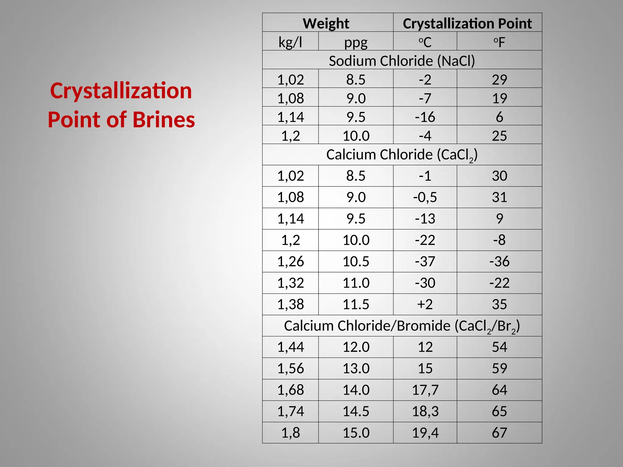
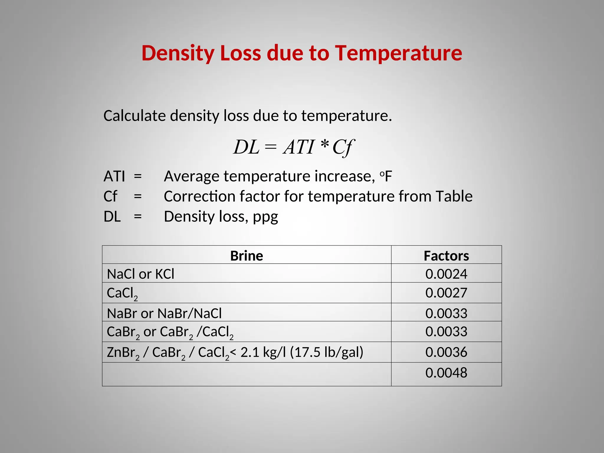
Density Loss dueto Temperature
Brine Factors
NaCl or KCl 0.0024
CaCl2 0.0027
NaBr or NaBr/NaCl 0.0033
CaBr2 or CaBr2 /CaCl2 0.0033
ZnBr2 / CaBr2 / CaCl2< 2.1 kg/l (17.5 lb/gal) 0.0036
0.0048
Calculate density loss due to temperature.
ATI = Average temperature increase, o
F
Cf = Correction factor for temperature from Table
DL = Density loss, ppg
Cf
*
ATI
DL =
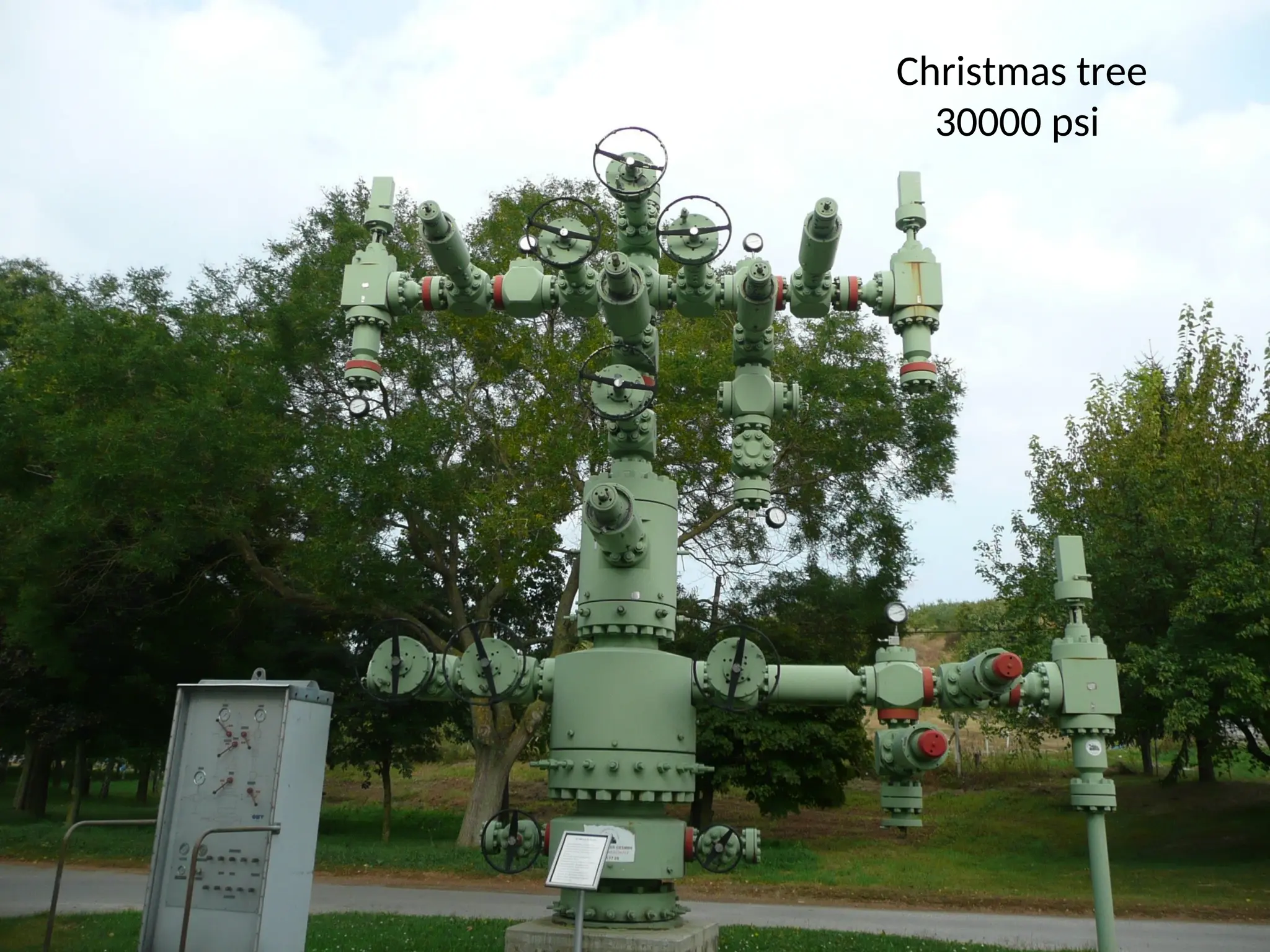
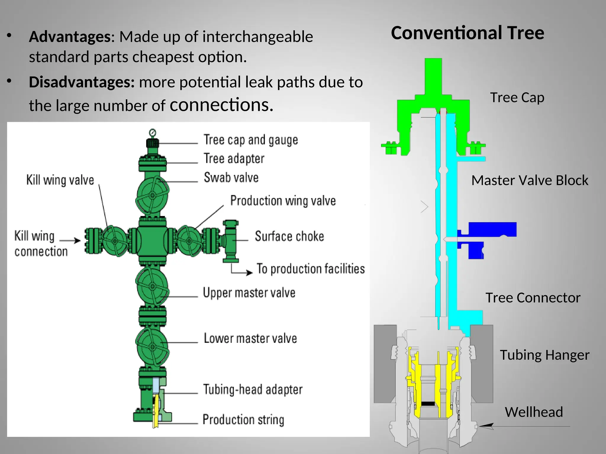
Conventional Tree
• Advantages:Made up of interchangeable
standard parts cheapest option.
• Disadvantages: more potential leak paths due to
the large number of connections.
Master Valve Block
Tree Cap
Tree Connector
Tubing Hanger
Wellhead
11.
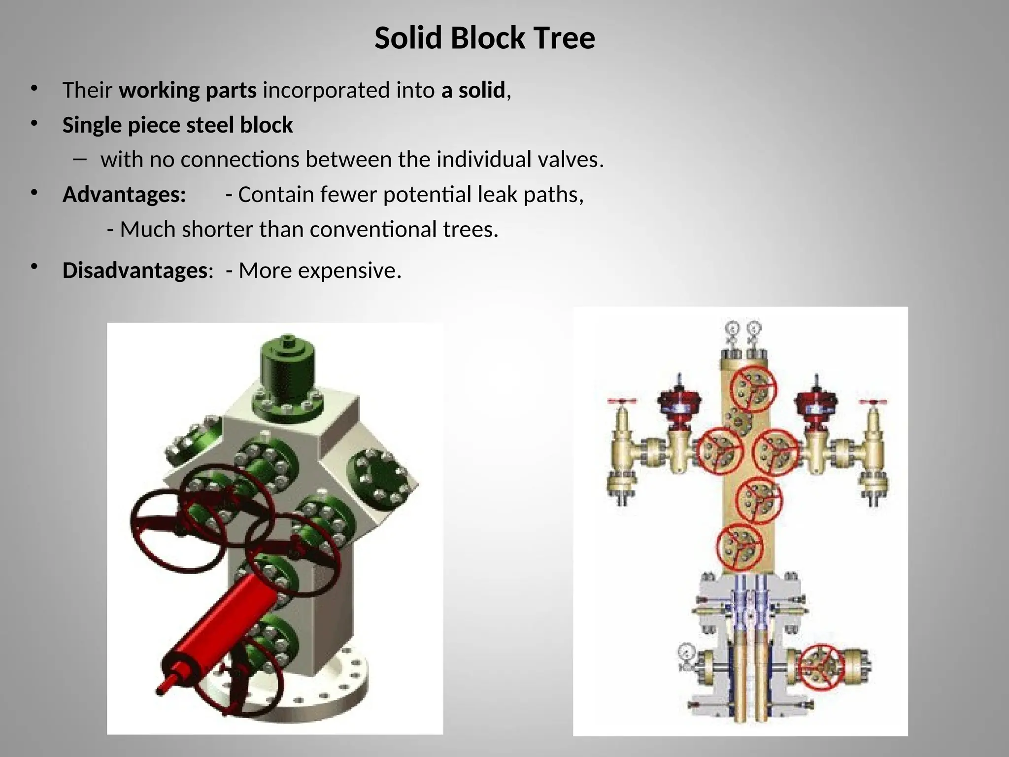
Solid Block Tree
•Their working parts incorporated into a solid,
• Single piece steel block
– with no connections between the individual valves.
• Advantages: - Contain fewer potential leak paths,
- Much shorter than conventional trees.
• Disadvantages: - More expensive.
12.
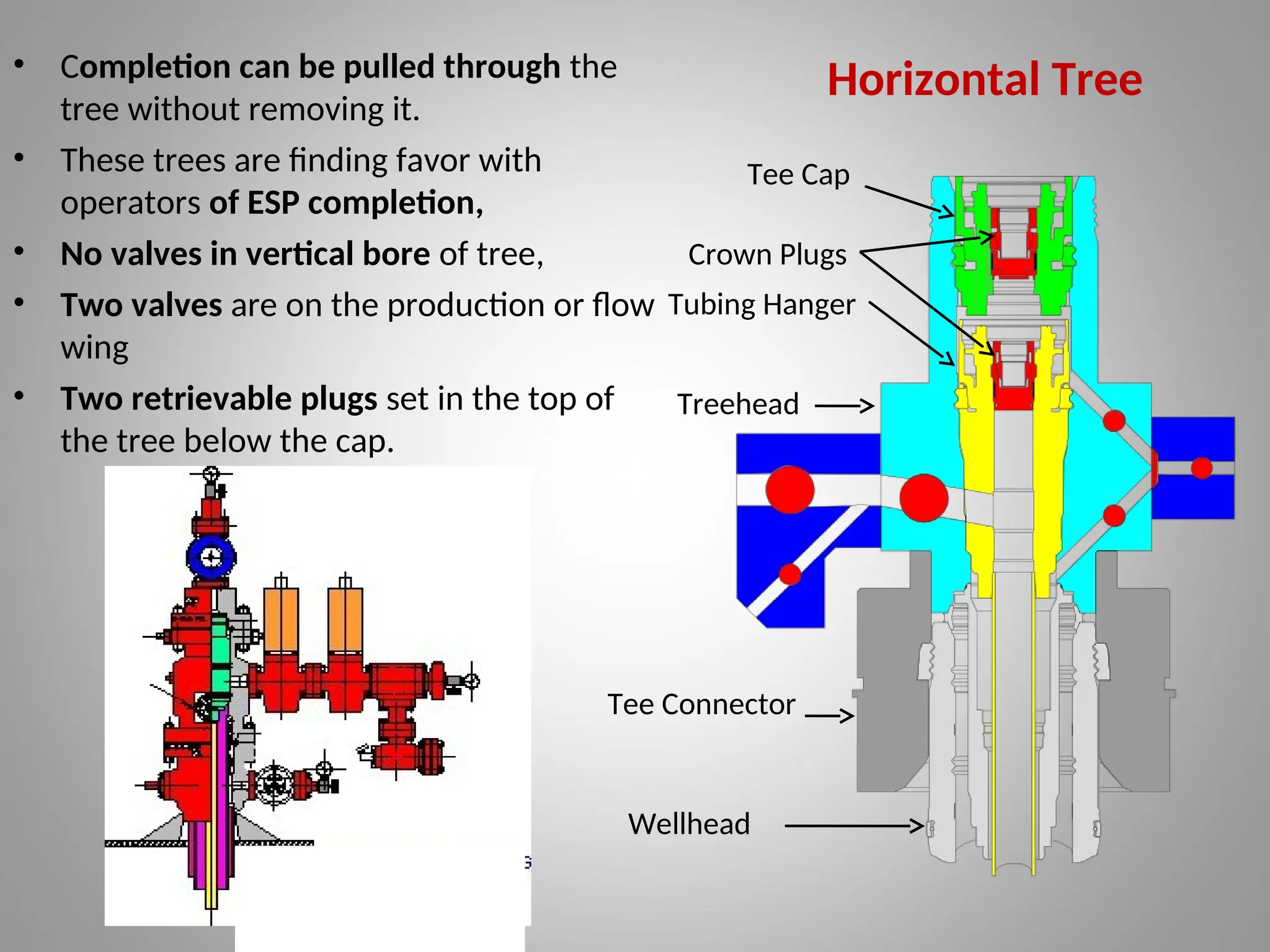
• Completion canbe pulled through the
tree without removing it.
• These trees are finding favor with
operators of ESP completion,
• No valves in vertical bore of tree,
• Two valves are on the production or flow
wing
• Two retrievable plugs set in the top of
the tree below the cap.
Horizontal Tree
Tee Cap
Crown Plugs
Tubing Hanger
Treehead
Tee Connector
Wellhead
13.
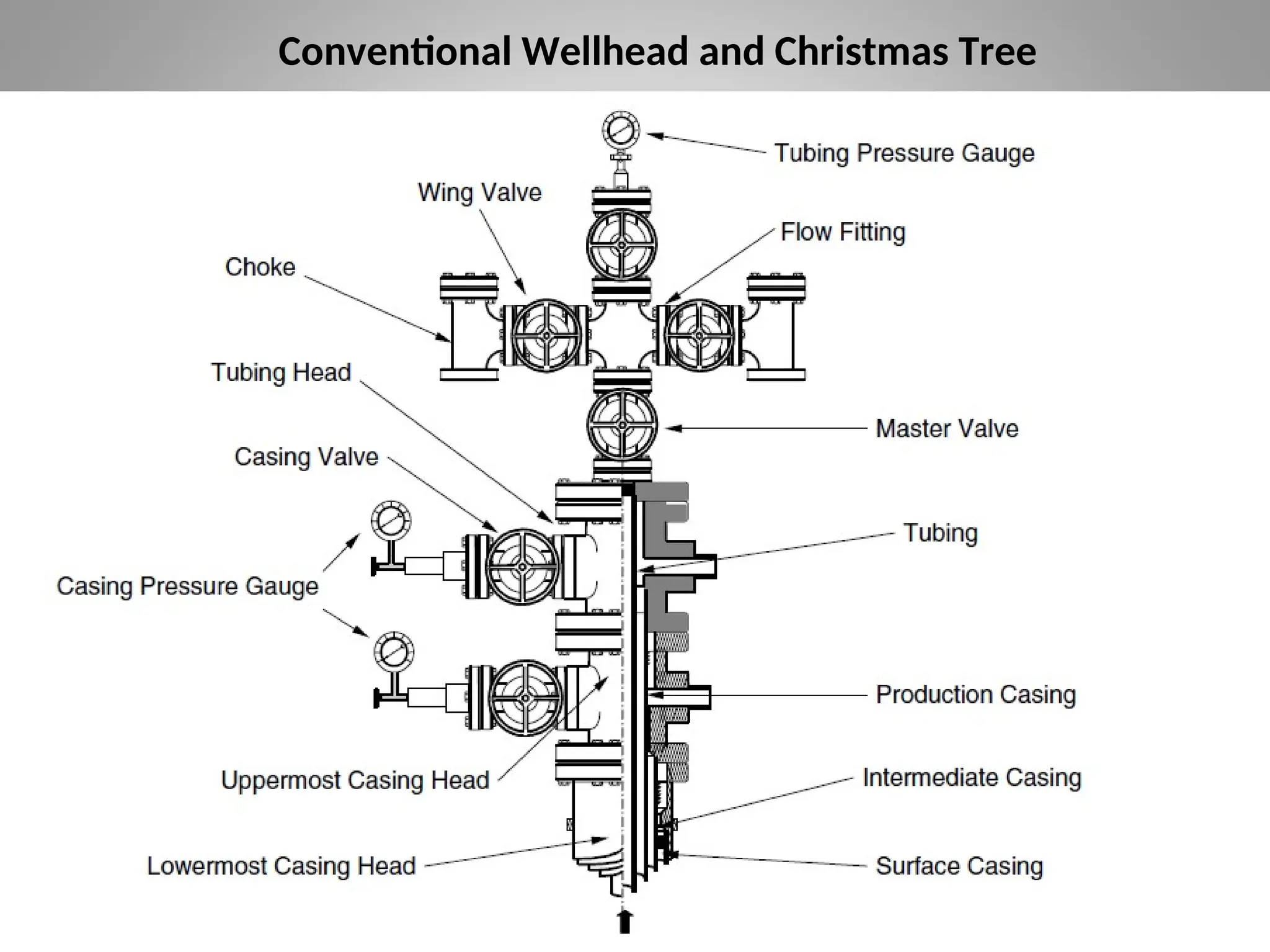
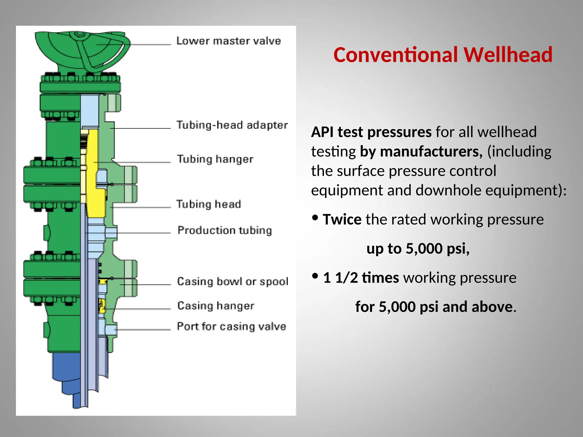
Conventional Wellhead
API testpressures for all wellhead
testing by manufacturers, (including
the surface pressure control
equipment and downhole equipment):
• Twice the rated working pressure
up to 5,000 psi,
• 1 1/2 times working pressure
for 5,000 psi and above.
14.
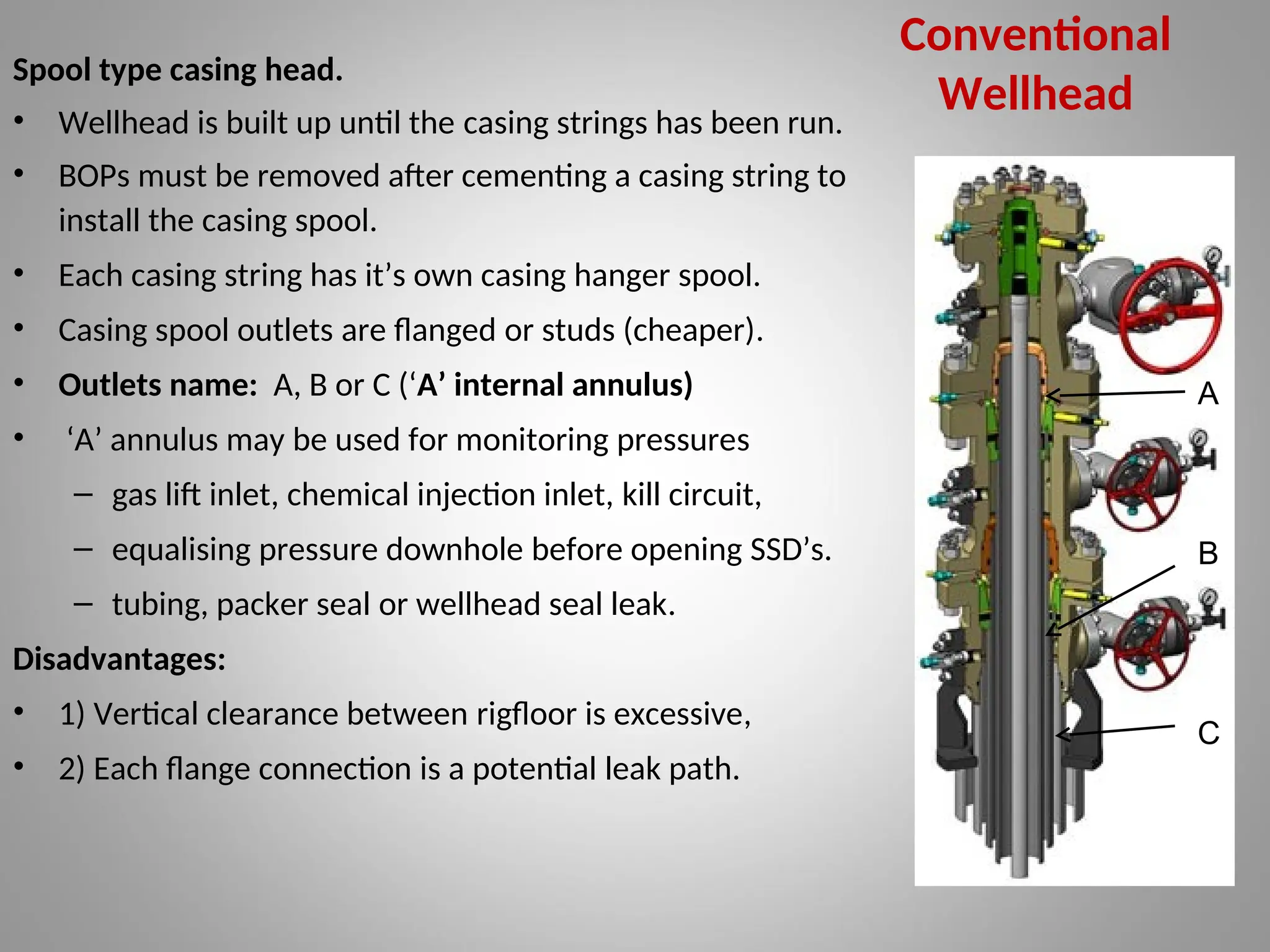
Spool type casinghead.
• Wellhead is built up until the casing strings has been run.
• BOPs must be removed after cementing a casing string to
install the casing spool.
• Each casing string has it’s own casing hanger spool.
• Casing spool outlets are flanged or studs (cheaper).
• Outlets name: A, B or C (‘A’ internal annulus)
• ‘A’ annulus may be used for monitoring pressures
– gas lift inlet, chemical injection inlet, kill circuit,
– equalising pressure downhole before opening SSD’s.
– tubing, packer seal or wellhead seal leak.
Disadvantages:
• 1) Vertical clearance between rigfloor is excessive,
• 2) Each flange connection is a potential leak path.
Conventional
Wellhead
A
B
C
15.
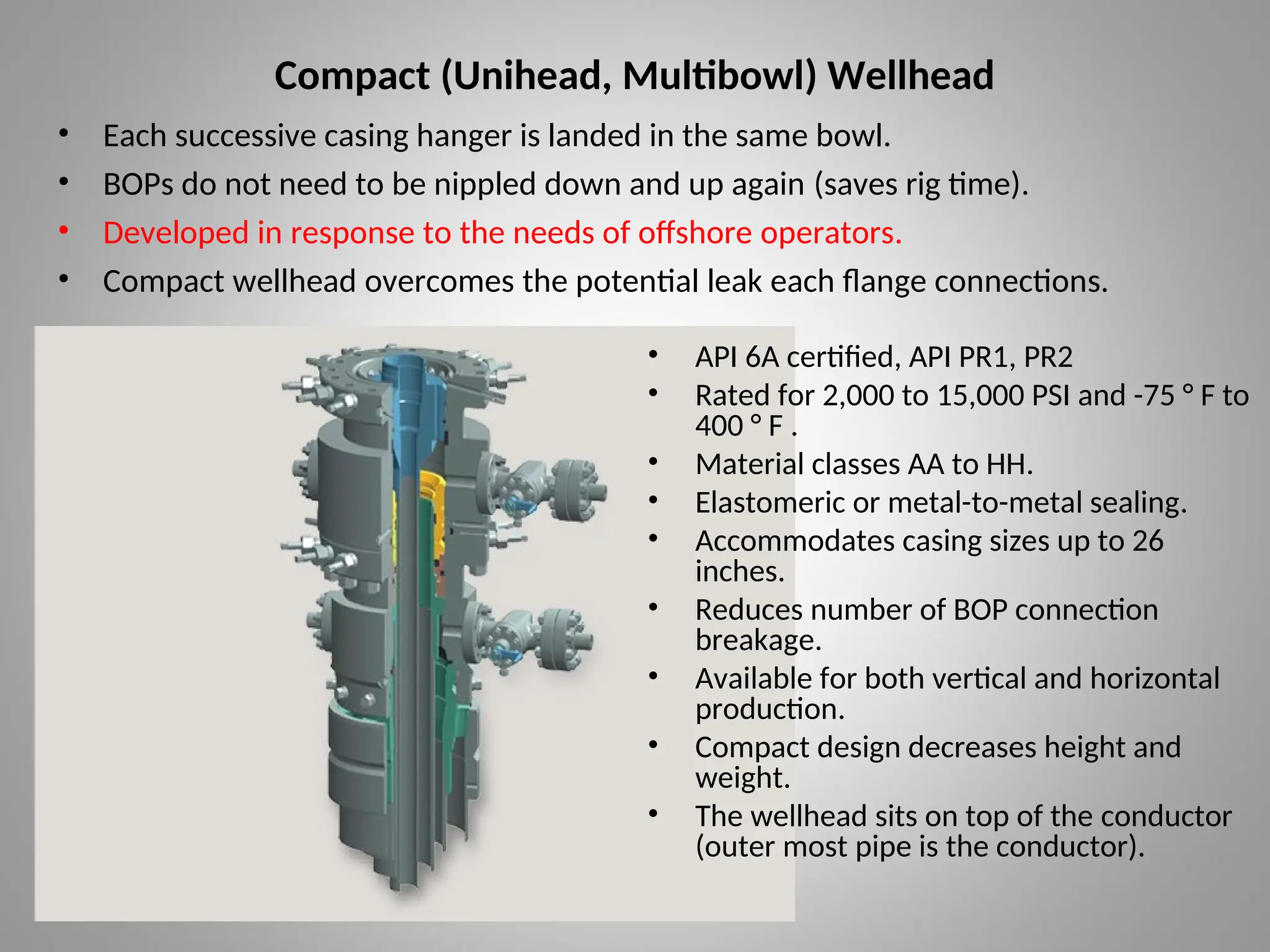
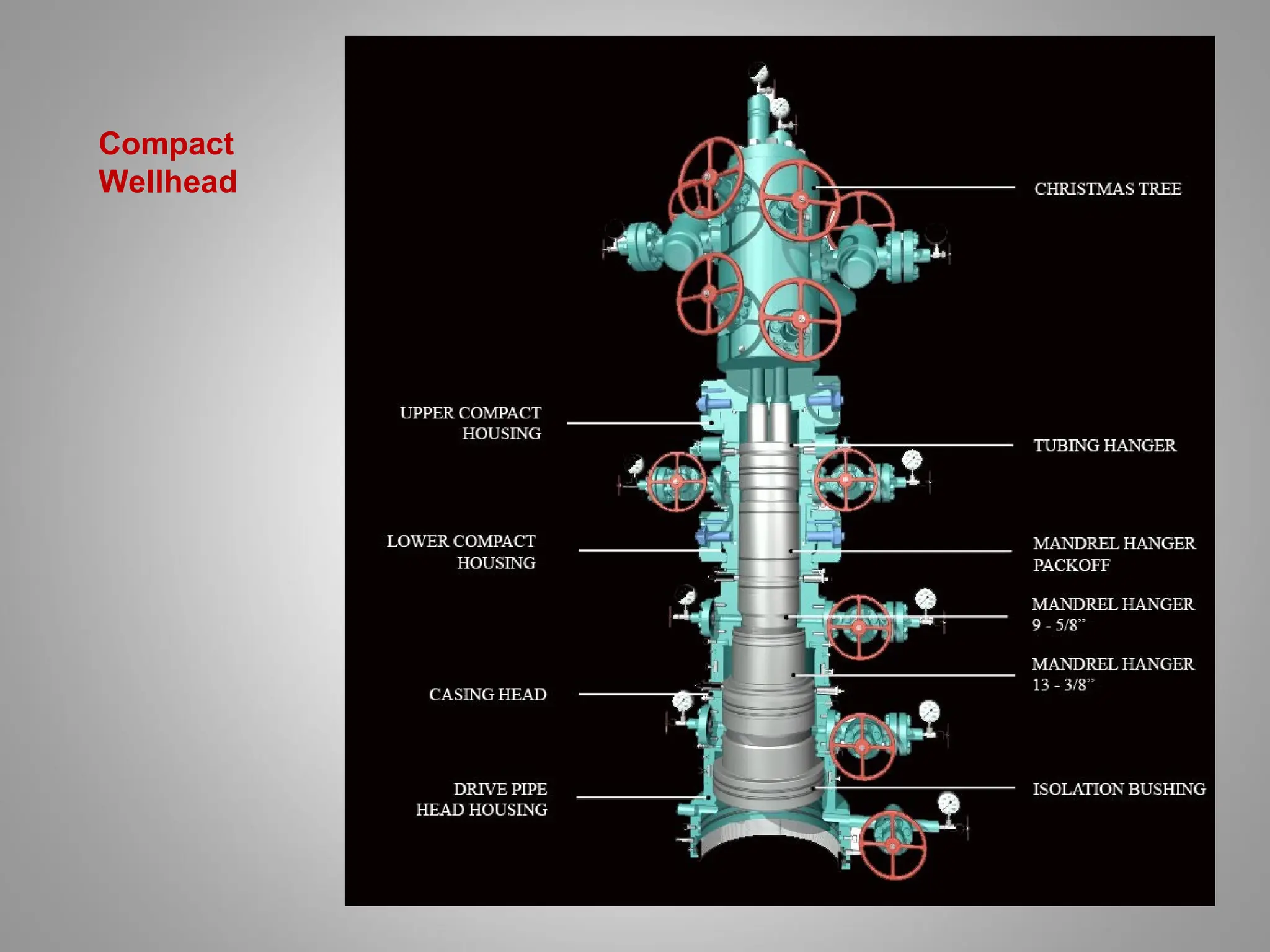
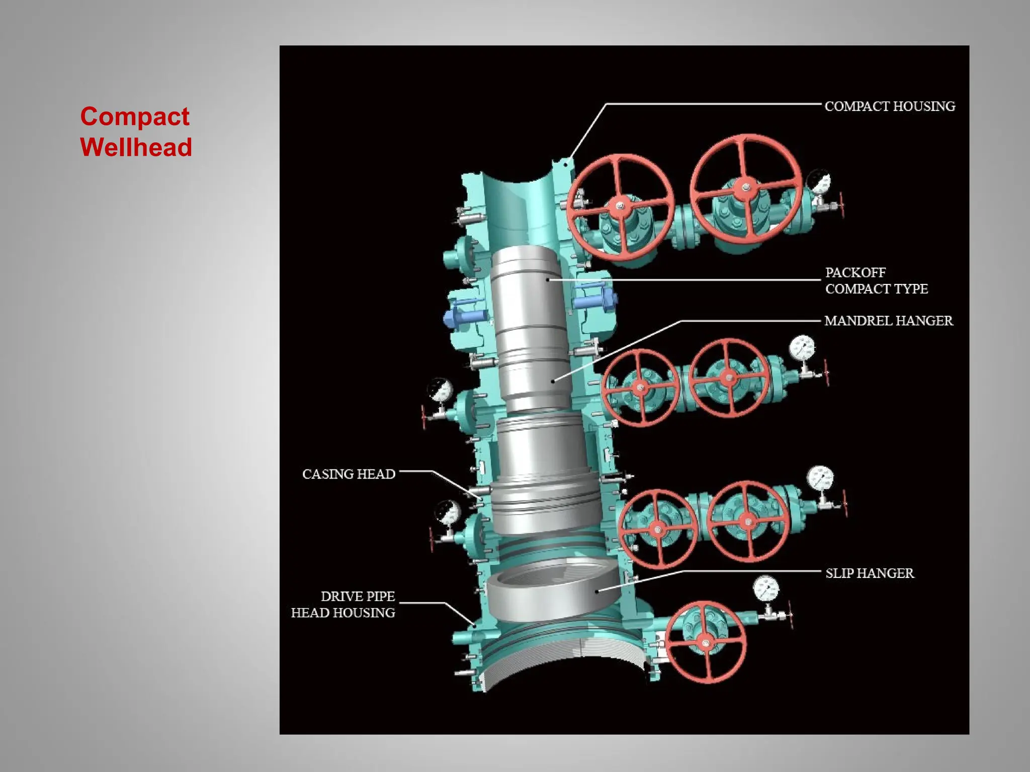
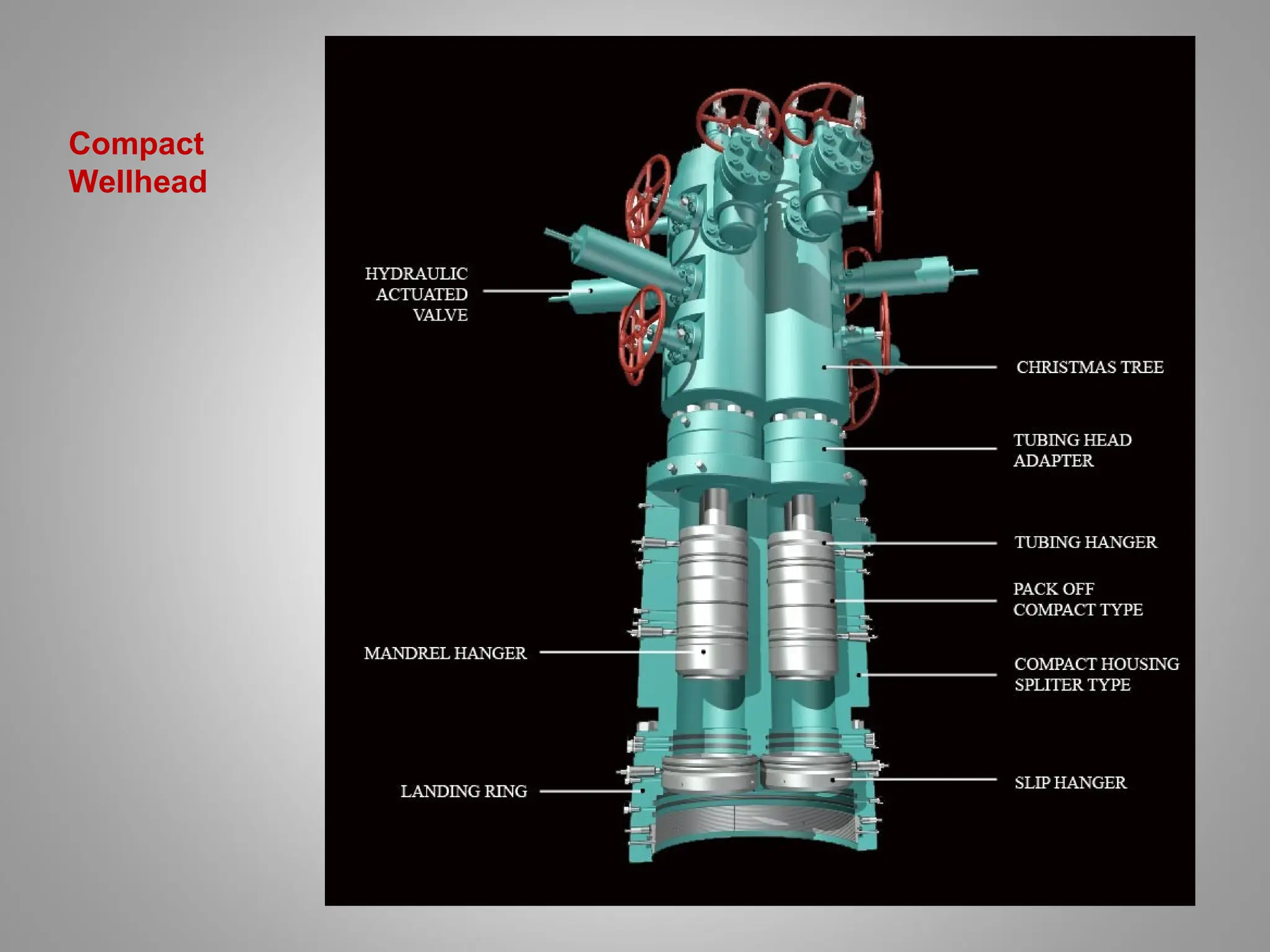
Compact (Unihead, Multibowl)Wellhead
• Each successive casing hanger is landed in the same bowl.
• BOPs do not need to be nippled down and up again (saves rig time).
• Developed in response to the needs of offshore operators.
• Compact wellhead overcomes the potential leak each flange connections.
• API 6A certified, API PR1, PR2
• Rated for 2,000 to 15,000 PSI and -75 ° F to
400 ° F .
• Material classes AA to HH.
• Elastomeric or metal-to-metal sealing.
• Accommodates casing sizes up to 26
inches.
• Reduces number of BOP connection
breakage.
• Available for both vertical and horizontal
production.
• Compact design decreases height and
weight.
• The wellhead sits on top of the conductor
(outer most pipe is the conductor).
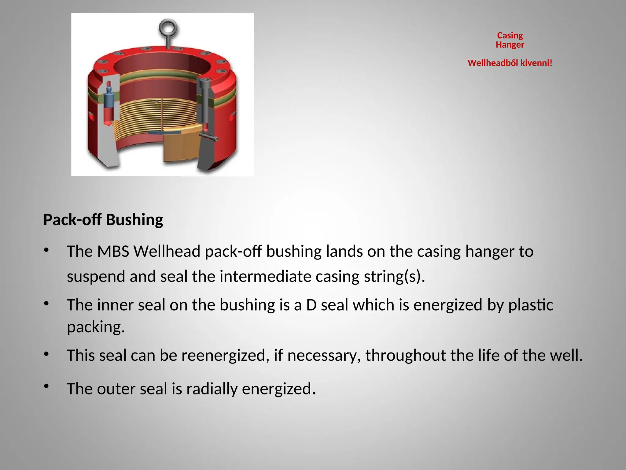
Pack-off Bushing
• TheMBS Wellhead pack-off bushing lands on the casing hanger to
suspend and seal the intermediate casing string(s).
• The inner seal on the bushing is a D seal which is energized by plastic
packing.
• This seal can be reenergized, if necessary, throughout the life of the well.
• The outer seal is radially energized.
Casing
Hanger
Wellheadből kivenni!
20.
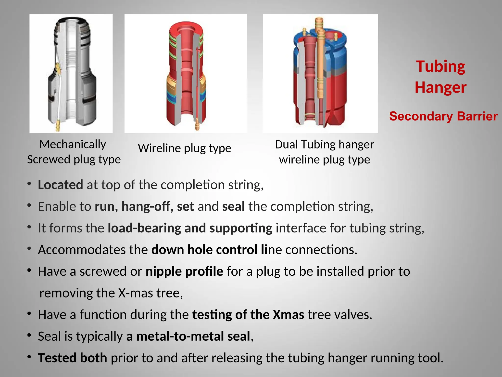
Tubing
Hanger
Mechanically
Screwed plug type
Wirelineplug type Dual Tubing hanger
wireline plug type
• Located at top of the completion string,
• Enable to run, hang-off, set and seal the completion string,
• It forms the load-bearing and supporting interface for tubing string,
• Accommodates the down hole control line connections.
• Have a screwed or nipple profile for a plug to be installed prior to
removing the X-mas tree,
• Have a function during the testing of the Xmas tree valves.
• Seal is typically a metal-to-metal seal,
• Tested both prior to and after releasing the tubing hanger running tool.
Secondary Barrier
21.
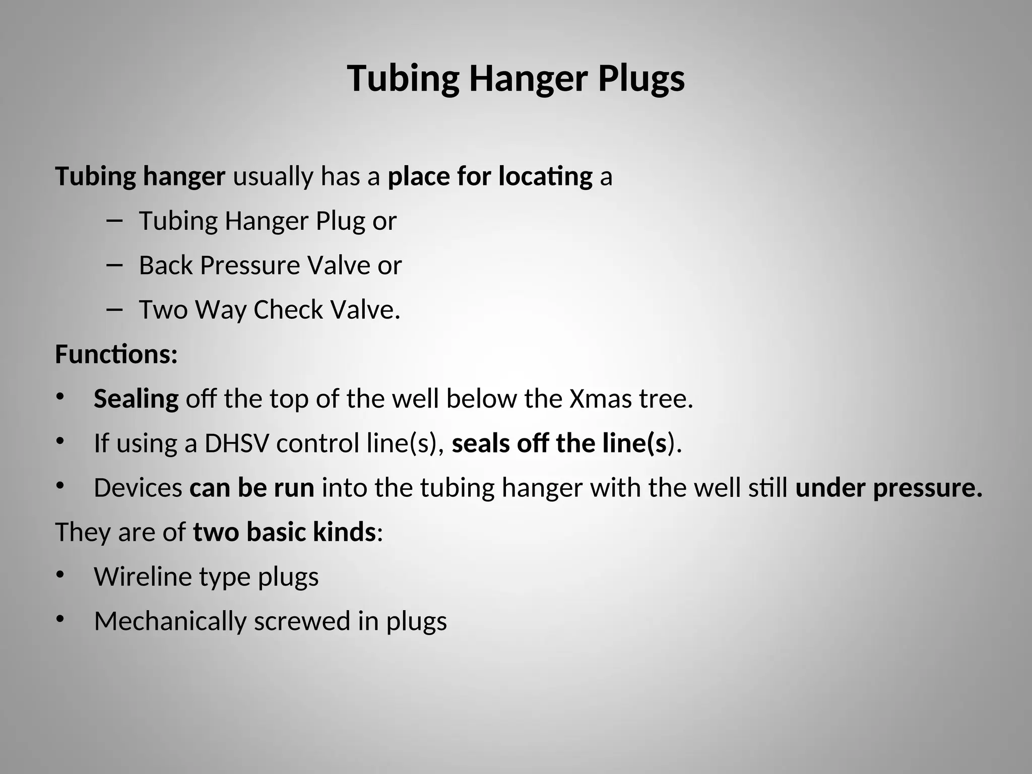
Tubing Hanger Plugs
Tubinghanger usually has a place for locating a
– Tubing Hanger Plug or
– Back Pressure Valve or
– Two Way Check Valve.
Functions:
• Sealing off the top of the well below the Xmas tree.
• If using a DHSV control line(s), seals off the line(s).
• Devices can be run into the tubing hanger with the well still under pressure.
They are of two basic kinds:
• Wireline type plugs
• Mechanically screwed in plugs
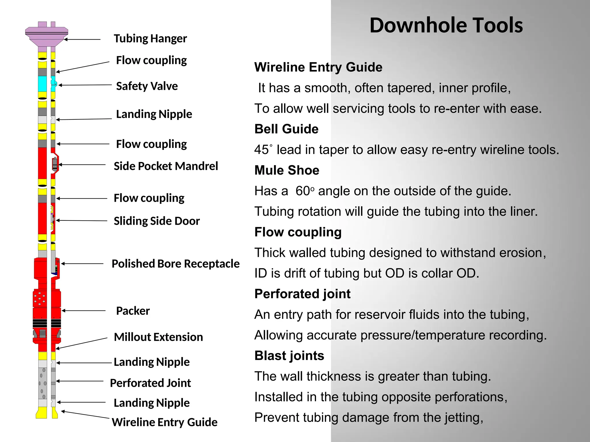
Downhole Tools
Tubing Hanger
Flowcoupling
Safety Valve
Landing Nipple
Flow coupling
Side Pocket Mandrel
Flow coupling
Sliding Side Door
Packer
Millout Extension
Perforated Joint
Polished Bore Receptacle
Landing Nipple
Landing Nipple
Wireline Entry Guide
Wireline Entry Guide
It has a smooth, often tapered, inner profile,
To allow well servicing tools to re-enter with ease.
Bell Guide
45˚ lead in taper to allow easy re-entry wireline tools.
Mule Shoe
Has a 60o
angle on the outside of the guide.
Tubing rotation will guide the tubing into the liner.
Flow coupling
Thick walled tubing designed to withstand erosion,
ID is drift of tubing but OD is collar OD.
Perforated joint
An entry path for reservoir fluids into the tubing,
Allowing accurate pressure/temperature recording.
Blast joints
The wall thickness is greater than tubing.
Installed in the tubing opposite perforations,
Prevent tubing damage from the jetting,
25.
Nipples
• Nipples areto allow a wireline device to pass through an
upper nipple and be set in a lower one.
• The most common locations for nipples are:
– Just above the packer/seal assembly/circulating device for
pressure testing.
– Just below the packer/millout extension/seal bore
extension for pressure setting of the packer.
– At the bottom of the completion to enable gauges to be
hung and left in the well for a time to monitor the
reservoir.
26.
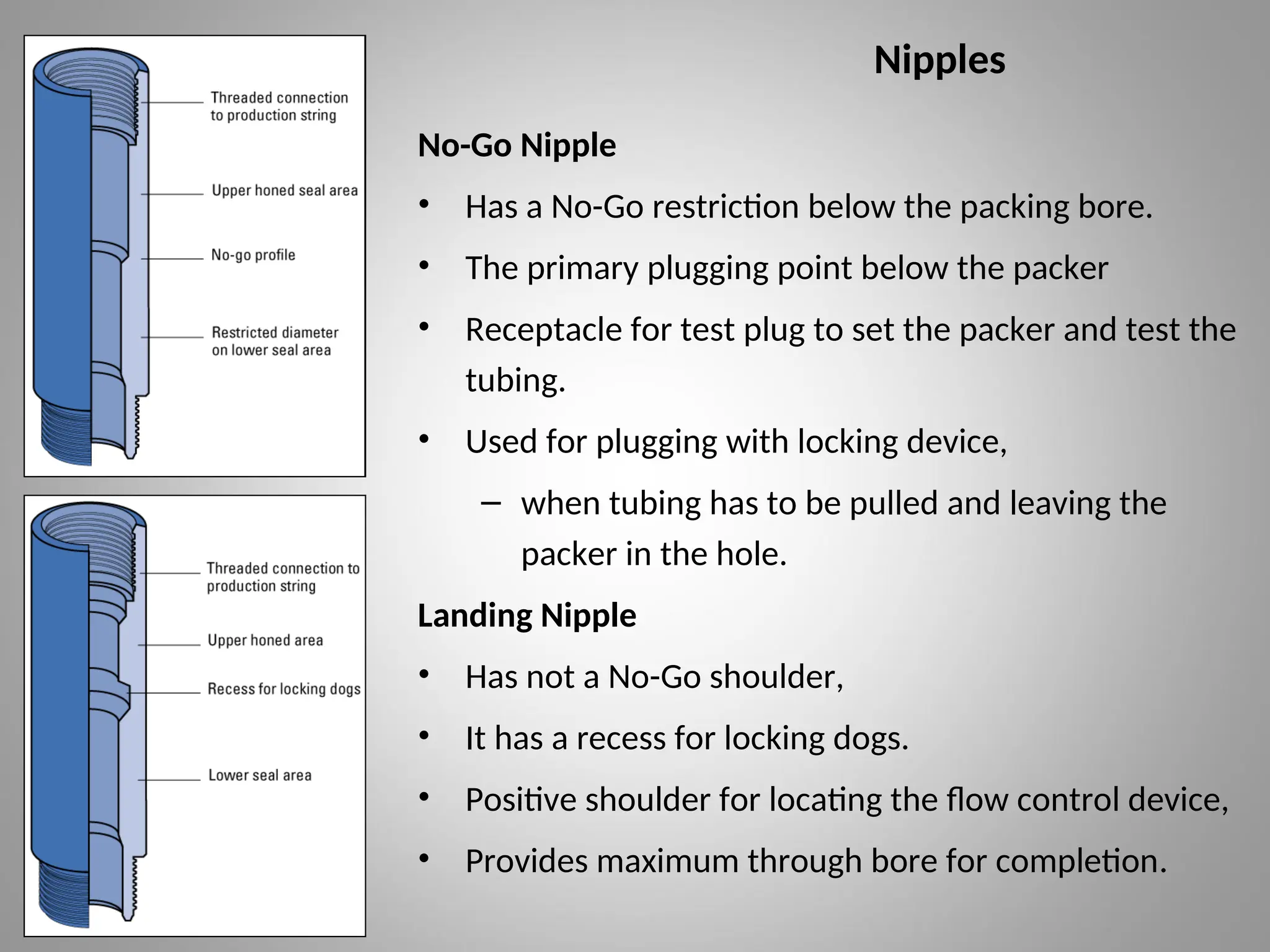
Nipples
No-Go Nipple
• Hasa No-Go restriction below the packing bore.
• The primary plugging point below the packer
• Receptacle for test plug to set the packer and test the
tubing.
• Used for plugging with locking device,
– when tubing has to be pulled and leaving the
packer in the hole.
Landing Nipple
• Has not a No-Go shoulder,
• It has a recess for locking dogs.
• Positive shoulder for locating the flow control device,
• Provides maximum through bore for completion.
27.
Downhole Safety Valve
Commonlyflapper valves which open downwards,
• It will isolate the reservoir fluids from surface.
It should be deep enough:
• to be unaffected by damage due to wellhead sabotage (explosions),
• to be unaffected by surface impact damage to the wellhead (collisions),
• to be unaffected by the crater that is formed by a major blowout,
• on closely spaced wellheads to be unaffected by another well being drilled
into it.
• In a single land well, the DHSV is often placed about 2-5 joints below the
ground level.
• There are offshore wells with the DHSV at 2500 ft below the tree.
• Allow the DHSV to be used as a barrier, when it has been closed and
inflow tested to prove that it is holding pressure.
28.
Surface Controlled Sub-SurfaceSafety Valves (SCSSV)
• It is a downhole safety device that can shut in a well in an emergency or
provide a barrier .
• It can be controlled from the surface by hydraulic pressure through control
line to the SCSSV.
• It is held open by hydraulic pressure supplied by a manifold at the surface.
• Damage to the wellhead or flowlines causes a low operating pressure. When
this pressure is lost, the safety valve automatically closes.
• It is failsafe and will isolate the wellbore in the event of a loss of the
wellhead pressure control.
Two main categories:
• Wireline Retrievable SCSSV
• Tubing Retrievable SCSSV.
29.
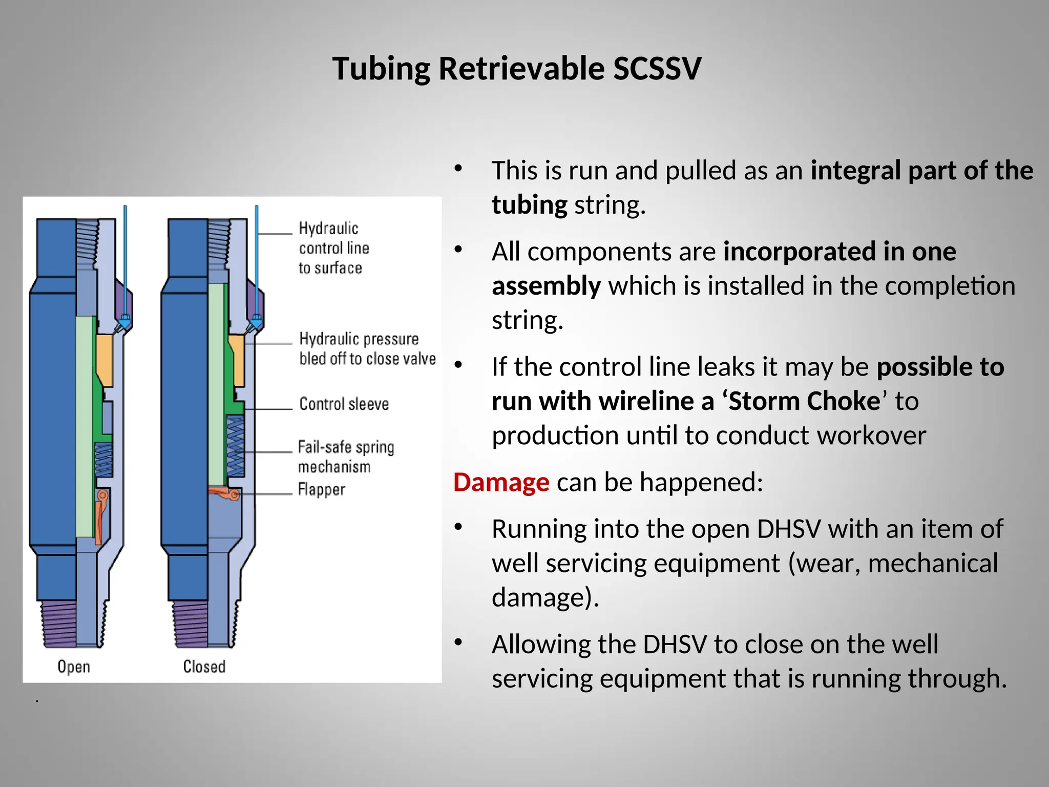
Tubing Retrievable SCSSV
•This is run and pulled as an integral part of the
tubing string.
• All components are incorporated in one
assembly which is installed in the completion
string.
• If the control line leaks it may be possible to
run with wireline a ‘Storm Choke’ to
production until to conduct workover
Damage can be happened:
• Running into the open DHSV with an item of
well servicing equipment (wear, mechanical
damage).
• Allowing the DHSV to close on the well
servicing equipment that is running through.
.
30.
Tubing Retrievable SCSSV
Disadvantage:
•It can be removed for repair only with doing a workover.
• For this reason, should a tubing retrievable DHSV fail, the facility exists to
permanently lock it open and insert another – wireline retrievable – safety
valve inside it.
Advantage:
• It has a much larger bore and hence flow through it,
• There is no facility for removing it before commencing intervention
operations,
• No potential flow path up the control line of the risk of damage to the DHSV,
• It is possible to run it open with an installed straddle across the valve.
• This straddle is pulled with wireline after the completion is set and the tree is
on.
31.
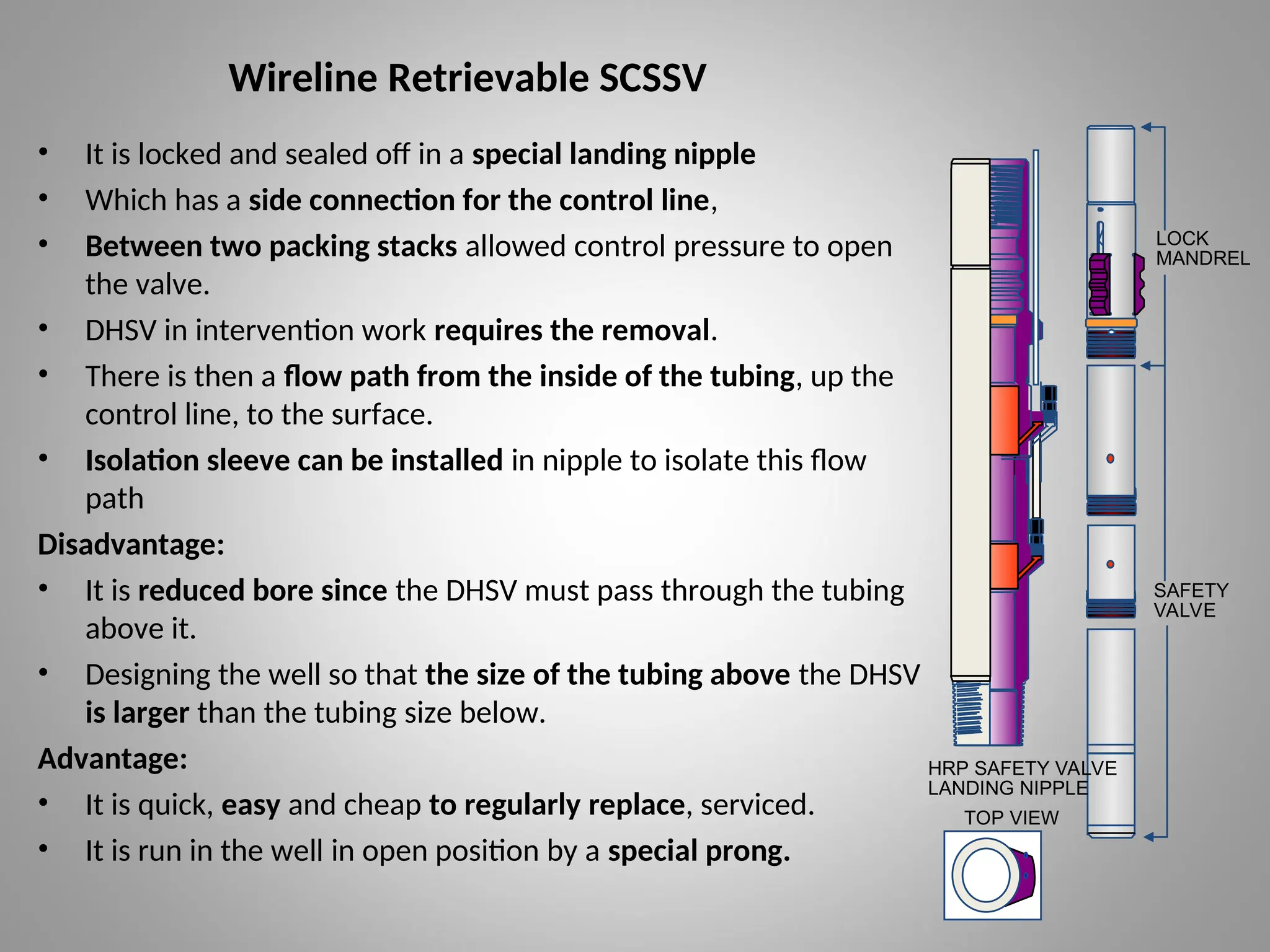
Wireline Retrievable SCSSV
•It is locked and sealed off in a special landing nipple
• Which has a side connection for the control line,
• Between two packing stacks allowed control pressure to open
the valve.
• DHSV in intervention work requires the removal.
• There is then a flow path from the inside of the tubing, up the
control line, to the surface.
• Isolation sleeve can be installed in nipple to isolate this flow
path
Disadvantage:
• It is reduced bore since the DHSV must pass through the tubing
above it.
• Designing the well so that the size of the tubing above the DHSV
is larger than the tubing size below.
Advantage:
• It is quick, easy and cheap to regularly replace, serviced.
• It is run in the well in open position by a special prong.
TOP VIEW
HRP SAFETY VALVE
LANDING NIPPLE
LOCK
MANDREL
SAFETY
VALVE
32.
Annulus Safety Valves
•For gas lift well, it is often a requirement to install the annular safety valve.
• Annular safety valve system provides a retrievable safety valve and
packer.
• This is usually combined with the tubing safety valve in one unit and
resembles a packer.
• It is placed at the same depth as an ordinary safety valve would be placed.
• This is generally a packer type installation,
• But may also be a casing polished bore nipple into which a packing
mandrel will seal.
• In the sealing device there is a valve mechanism operated by hydraulic
pressure similar to an SCSSV.
• The valve mechanism opens the communication path from the annulus
below to the annulus above the valve and is fail-safe closed.
33.
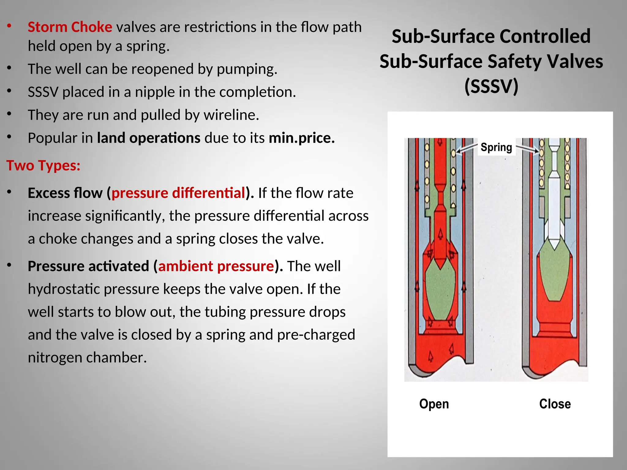
Sub-Surface Controlled
Sub-Surface SafetyValves
(SSSV)
• Storm Choke valves are restrictions in the flow path
held open by a spring.
• The well can be reopened by pumping.
• SSSV placed in a nipple in the completion.
• They are run and pulled by wireline.
• Popular in land operations due to its min.price.
Two Types:
• Excess flow (pressure differential). If the flow rate
increase significantly, the pressure differential across
a choke changes and a spring closes the valve.
• Pressure activated (ambient pressure). The well
hydrostatic pressure keeps the valve open. If the
well starts to blow out, the tubing pressure drops
and the valve is closed by a spring and pre-charged
nitrogen chamber.
Spring
Open Close
34.
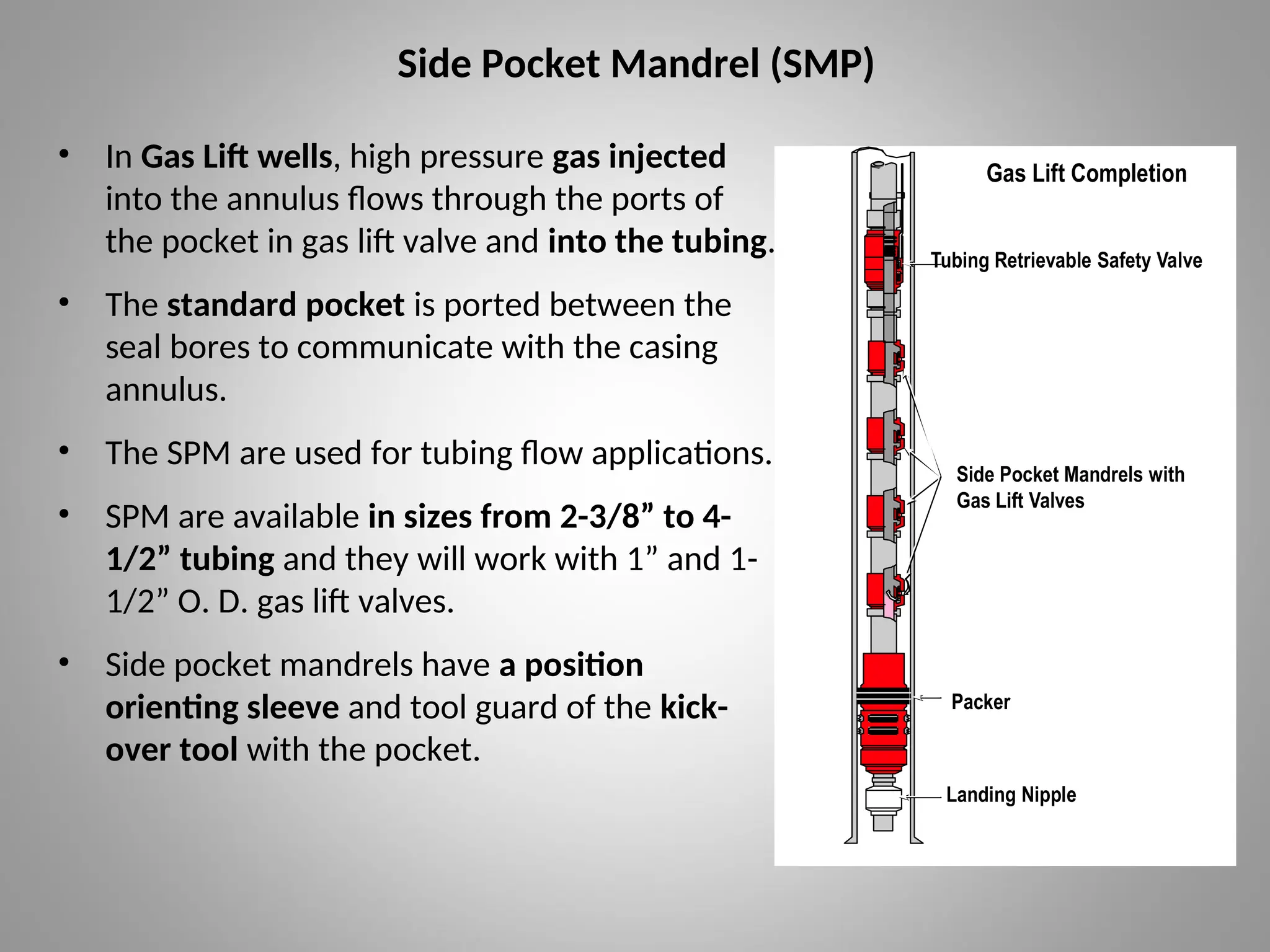
Side Pocket Mandrel(SMP)
• In Gas Lift wells, high pressure gas injected
into the annulus flows through the ports of
the pocket in gas lift valve and into the tubing.
• The standard pocket is ported between the
seal bores to communicate with the casing
annulus.
• The SPM are used for tubing flow applications.
• SPM are available in sizes from 2-3/8” to 4-
1/2” tubing and they will work with 1” and 1-
1/2” O. D. gas lift valves.
• Side pocket mandrels have a position
orienting sleeve and tool guard of the kick-
over tool with the pocket.
Gas Lift Completion
Tubing Retrievable Safety Valve
Packer
Landing Nipple
VII GLC 1
CN00049F
Side Pocket Mandrels with
Gas Lift Valves
35.
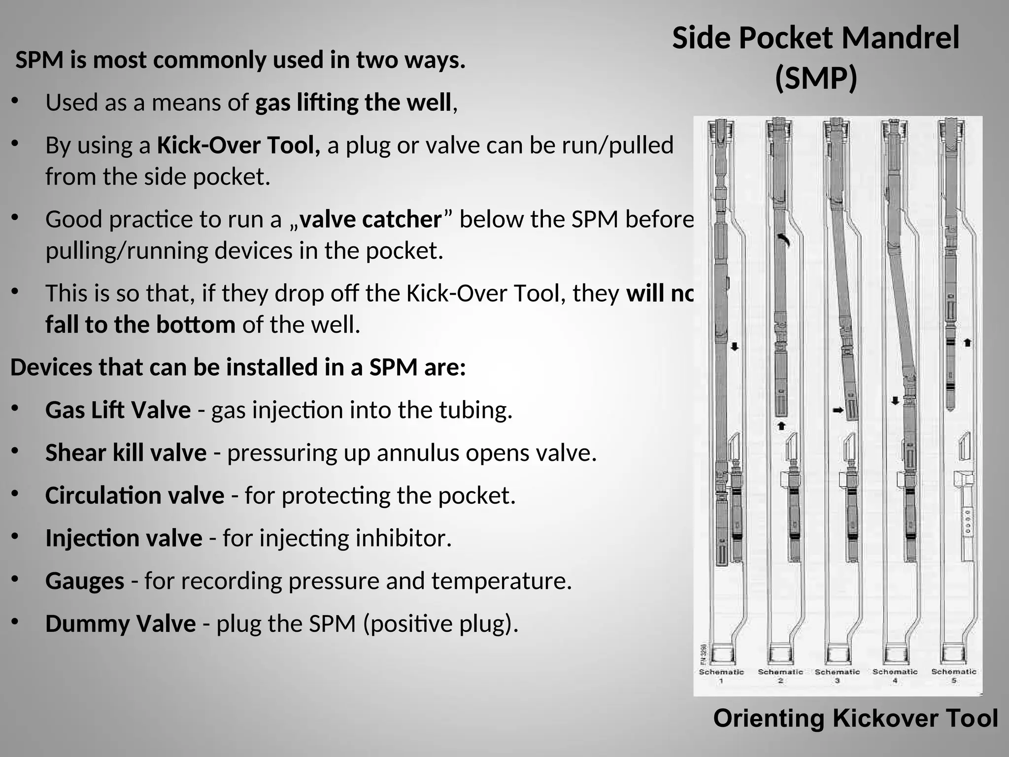
Side Pocket Mandrel
(SMP)
SPMis most commonly used in two ways.
• Used as a means of gas lifting the well,
• By using a Kick-Over Tool, a plug or valve can be run/pulled
from the side pocket.
• Good practice to run a „valve catcher” below the SPM before
pulling/running devices in the pocket.
• This is so that, if they drop off the Kick-Over Tool, they will not
fall to the bottom of the well.
Devices that can be installed in a SPM are:
• Gas Lift Valve - gas injection into the tubing.
• Shear kill valve - pressuring up annulus opens valve.
• Circulation valve - for protecting the pocket.
• Injection valve - for injecting inhibitor.
• Gauges - for recording pressure and temperature.
• Dummy Valve - plug the SPM (positive plug).
Orienting Kickover Tool
36.
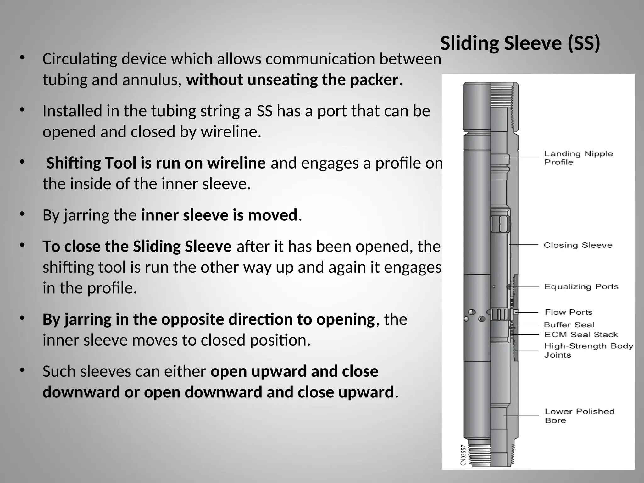
Sliding Sleeve (SS)
•Circulating device which allows communication between
tubing and annulus, without unseating the packer.
• Installed in the tubing string a SS has a port that can be
opened and closed by wireline.
• Shifting Tool is run on wireline and engages a profile on
the inside of the inner sleeve.
• By jarring the inner sleeve is moved.
• To close the Sliding Sleeve after it has been opened, the
shifting tool is run the other way up and again it engages
in the profile.
• By jarring in the opposite direction to opening, the
inner sleeve moves to closed position.
• Such sleeves can either open upward and close
downward or open downward and close upward.
37.
Downhole Tools
Packers
• Apacker seals the annular space between the casing and the tubing.
• It prevents the wellbore fluids from contacting the casing above the
packer and isolates the annulus from the pressure inside the tubing.
• It protects the casing from high production or stimulation pressures
and corrosive fluids.
• Multiple packers isolate dual or triple completion.
• Special packers are also available for squeeze cementing, acidizing, and
fracturing.
There are two main groups:
• Retrievable Packers
• Permanent Packers
38.
Downhole Tools
Packers
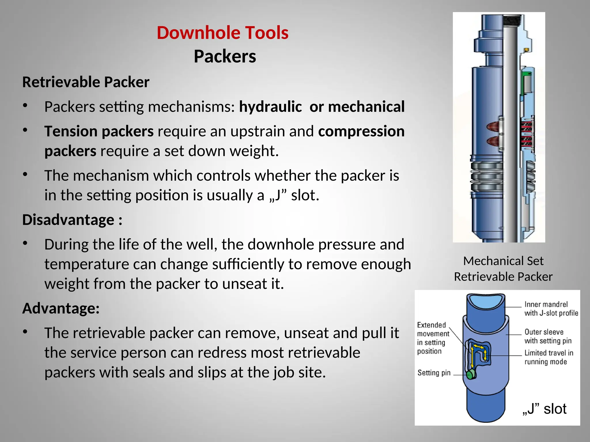
Retrievable Packer
•Packers setting mechanisms: hydraulic or mechanical
• Tension packers require an upstrain and compression
packers require a set down weight.
• The mechanism which controls whether the packer is
in the setting position is usually a „J” slot.
Disadvantage :
• During the life of the well, the downhole pressure and
temperature can change sufficiently to remove enough
weight from the packer to unseat it.
Advantage:
• The retrievable packer can remove, unseat and pull it
the service person can redress most retrievable
packers with seals and slips at the job site.
„J” slot
Mechanical Set
Retrievable Packer
39.
Downhole Tools
Packers
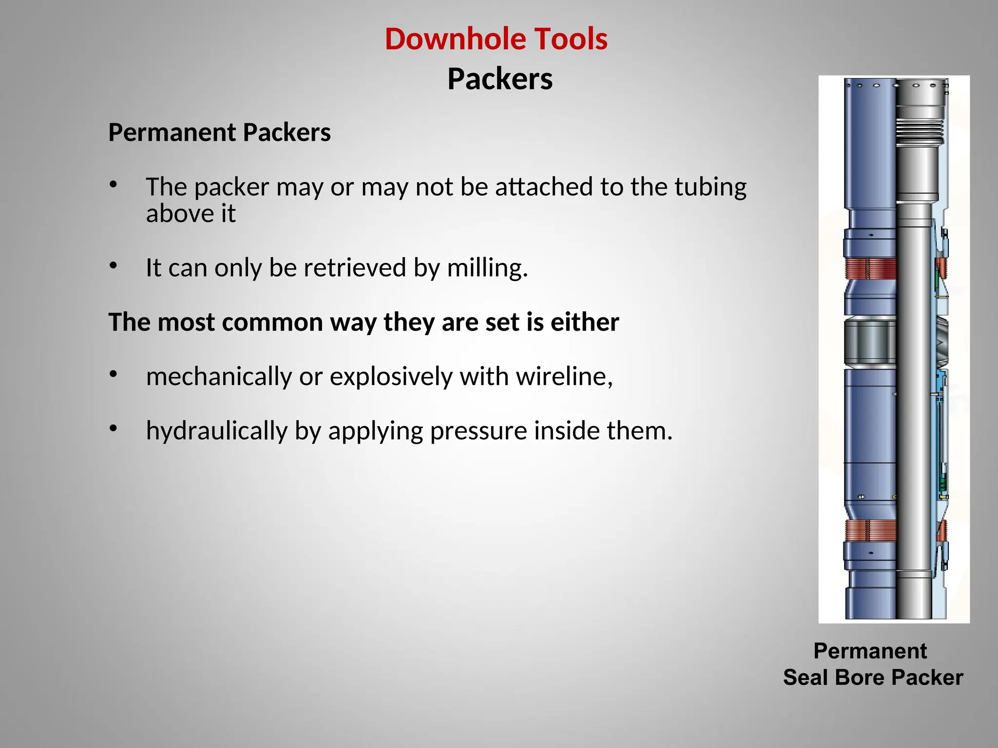
Permanent Packers
•The packer may or may not be attached to the tubing
above it
• It can only be retrieved by milling.
The most common way they are set is either
• mechanically or explosively with wireline,
• hydraulically by applying pressure inside them.
Permanent
Seal Bore Packer
40.
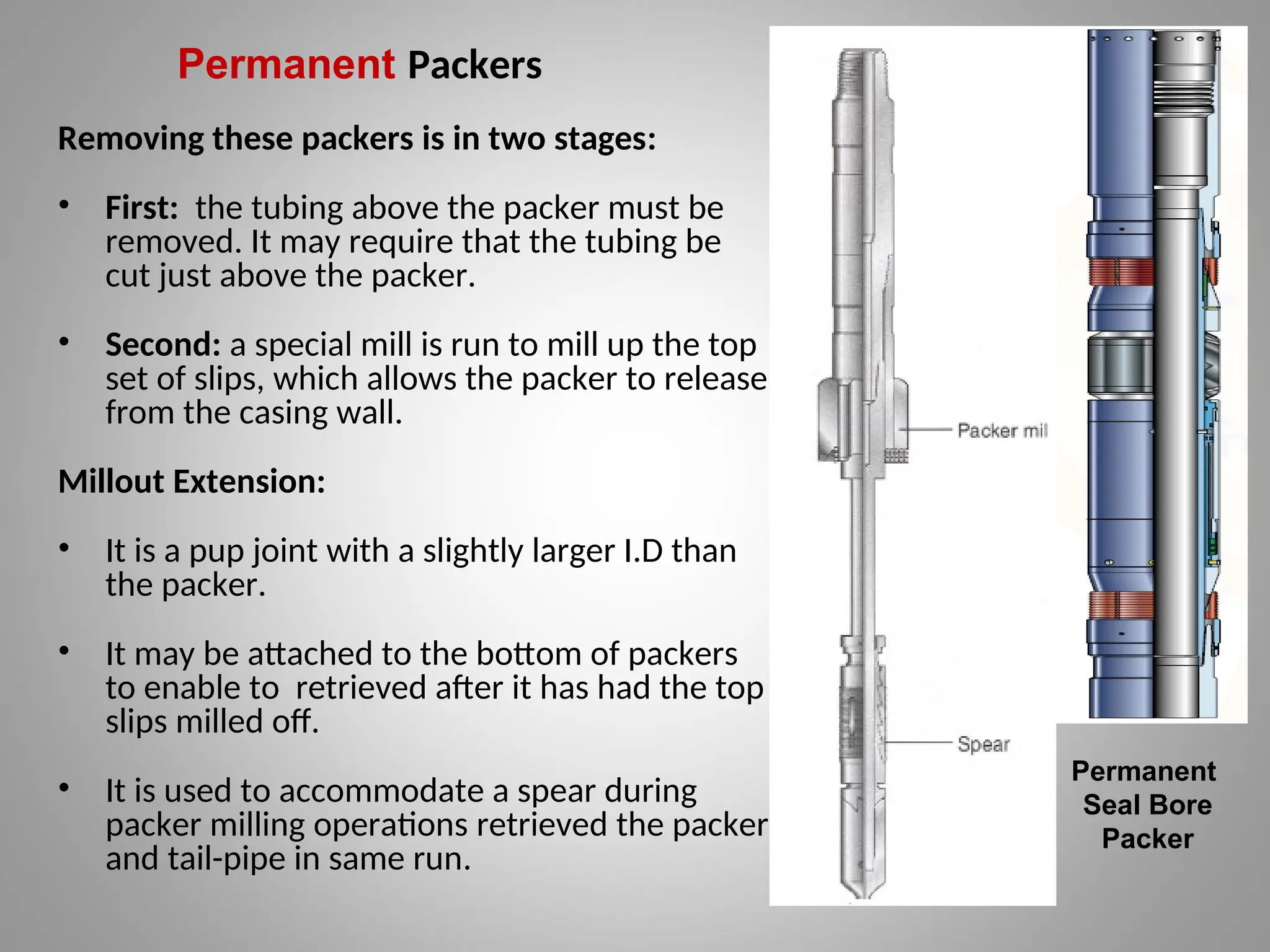
Permanent Packers
Removing thesepackers is in two stages:
• First: the tubing above the packer must be
removed. It may require that the tubing be
cut just above the packer.
• Second: a special mill is run to mill up the top
set of slips, which allows the packer to release
from the casing wall.
Millout Extension:
• It is a pup joint with a slightly larger I.D than
the packer.
• It may be attached to the bottom of packers
to enable to retrieved after it has had the top
slips milled off.
• It is used to accommodate a spear during
packer milling operations retrieved the packer
and tail-pipe in same run.
Permanent
Seal Bore
Packer
41.
Downhole Tools
Packers
Seal Assemblies
•Seal Assemblies are installed in packers to prevent pressure from
escaping between the tubing and the packer.
• It run on the bottom of the tubing string and inserted into the packer.
• A latch-type seal nipple is also available that locks into the packer so that
tension may be pulled on the tubing if desired.
• There is a set of seals that are able to slide up and down inside or outside
another section.
• This maintains isolation of the tubing and its annulus whilst allowing for
tubing movement.
42.
Downhole Tools
Packers
Different typesof sealing:
•Tubing Seal Assembly: seals are able to move up and down inside a seal
bore in the packer itself.
•Seal Bore Extension: attached to the bottom of the packer, it can be very
much longer allowing for greater tubing movement.
•Slick joint: may be run above the packer.
– This is a single unit designed for running the tubing attached to the
packer.
– Once the packer has been set, the pins are sheared, the hanger
landed and the slick joint is able to allow tubing movement.
•Tubing anchor: If the tubing is not screwed directly into the top of the
permanent packer, it may be attached by means of a tubing anchor.
– This is a device that stabs into the top of the packer and seals off
inside the top of the packer.
43.
Downhole Tools
Packers
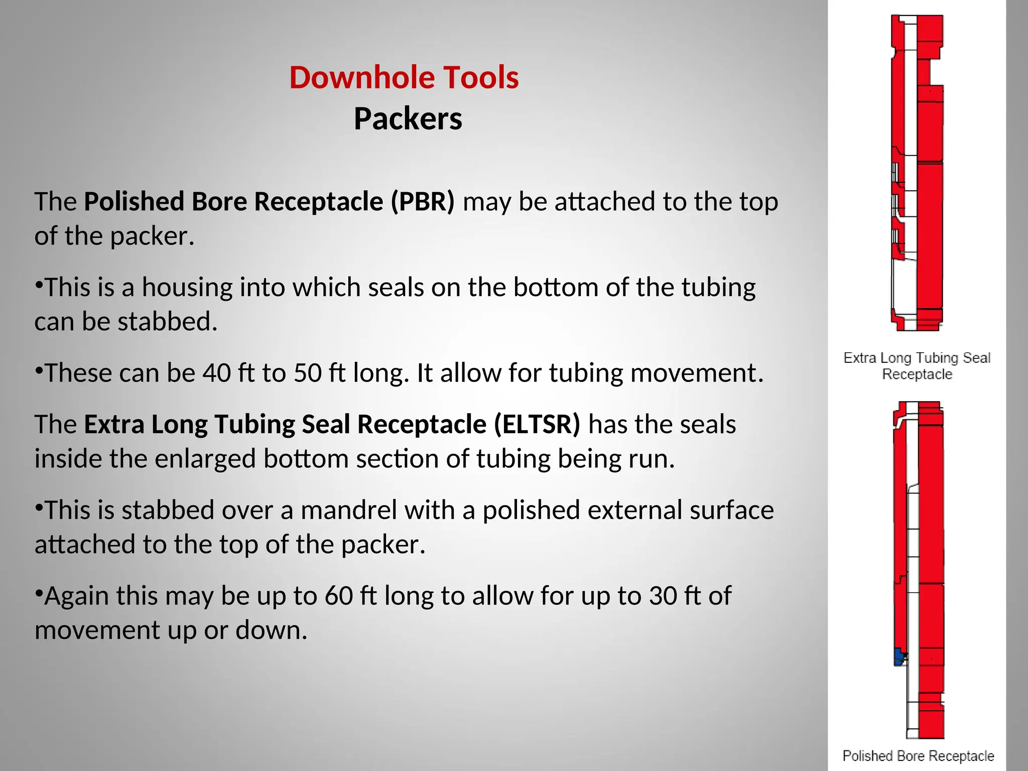
The PolishedBore Receptacle (PBR) may be attached to the top
of the packer.
•This is a housing into which seals on the bottom of the tubing
can be stabbed.
•These can be 40 ft to 50 ft long. It allow for tubing movement.
The Extra Long Tubing Seal Receptacle (ELTSR) has the seals
inside the enlarged bottom section of tubing being run.
•This is stabbed over a mandrel with a polished external surface
attached to the top of the packer.
•Again this may be up to 60 ft long to allow for up to 30 ft of
movement up or down.
44.
Downhole Tools
Flow ControlDevices
Blanking Plugs (Positive plugs)
•They seal off in the nipple and hold pressure from both directions.
•The pressure rating of plug should always be checked if it is
planned to pressure up against it from above.
45.
Flow Control Devices
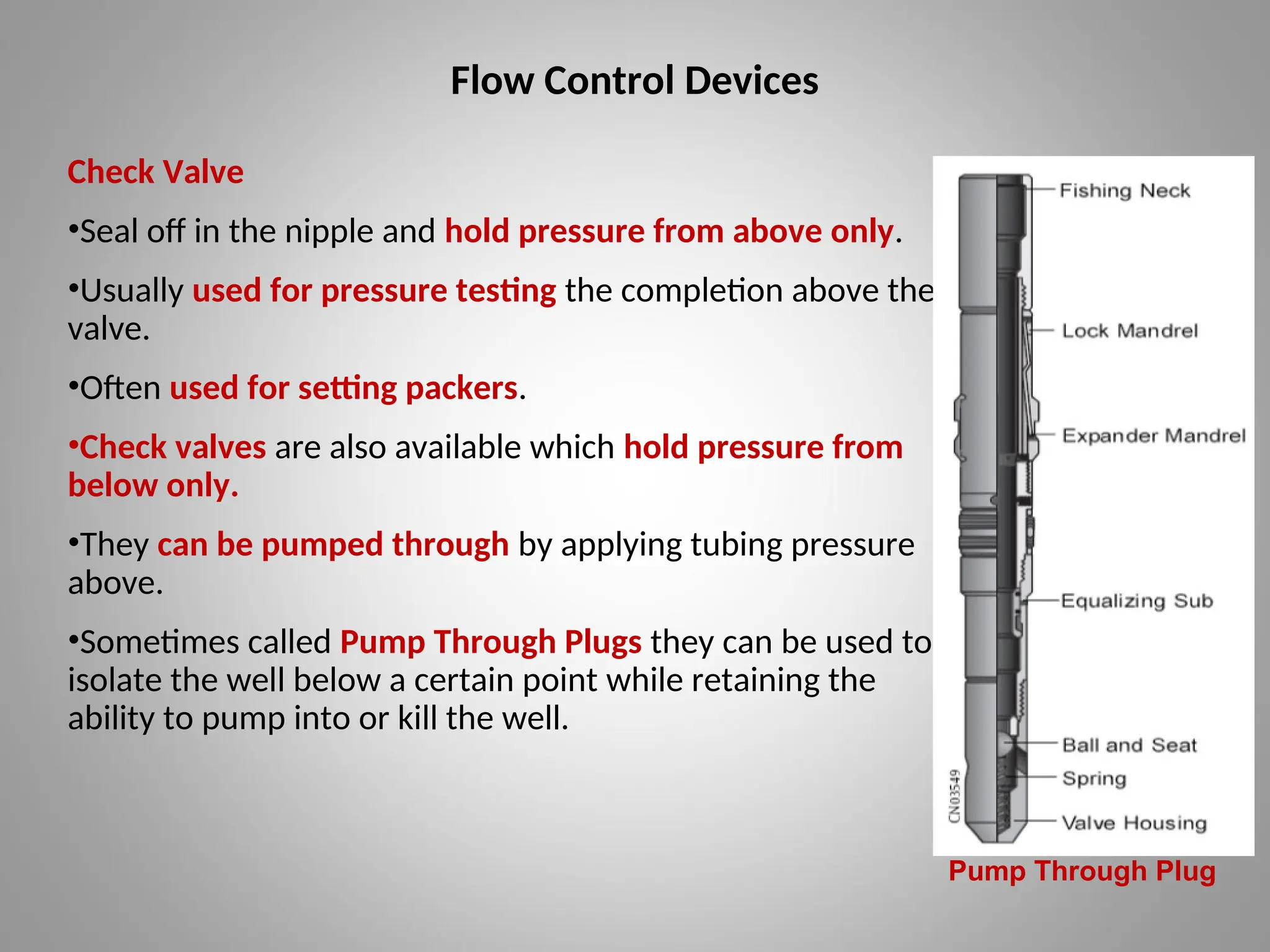
CheckValve
•Seal off in the nipple and hold pressure from above only.
•Usually used for pressure testing the completion above the
valve.
•Often used for setting packers.
•Check valves are also available which hold pressure from
below only.
•They can be pumped through by applying tubing pressure
above.
•Sometimes called Pump Through Plugs they can be used to
isolate the well below a certain point while retaining the
ability to pump into or kill the well.
Pump Through Plug
46.
Flow Control Devices
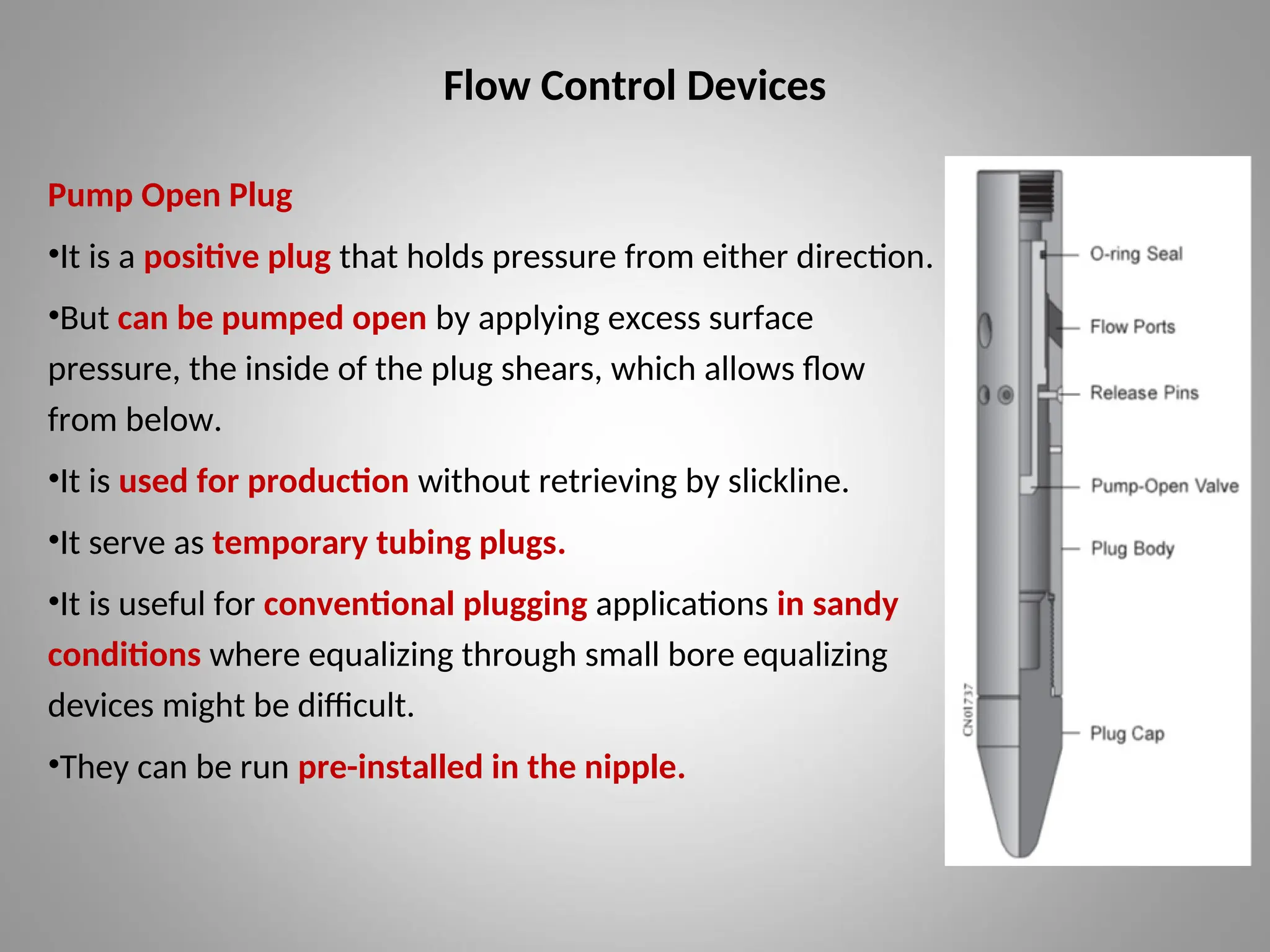
PumpOpen Plug
•It is a positive plug that holds pressure from either direction.
•But can be pumped open by applying excess surface
pressure, the inside of the plug shears, which allows flow
from below.
•It is used for production without retrieving by slickline.
•It serve as temporary tubing plugs.
•It is useful for conventional plugging applications in sandy
conditions where equalizing through small bore equalizing
devices might be difficult.
•They can be run pre-installed in the nipple.
47.
Flow Control Devices
PressureCycle Plugs
•The overbalance pressure above the plug must be cycled from zero to a pre-
set value of perhaps 2500 psi a fixed number of times before the plug opens.
•The number of cycles can be pre-set to anything up to 20.
•The pressure cycle plug offers more flexibility and security before the plug is
opened.
Pump Out Plugs
•When the correct pressure is applied above the plug, the bottom of the plug
shears off and is left downhole.
•They can give a greater flow path than pump open plugs although they have
the same disadvantage of leaving a restriction in the nipple.
48.
Flow Control Devices
RetrievableBridge Plugs
•It can be set anywhere in the tubing
•It is usually set by an explosive force, having been run on electric line.
•In this respect they are like a miniature packer in that they have slips and
packing elements.
•Slickline or Coiled Tubing can however pull them.
Pump Out Subs
•Same principle as the pump out plug, they are attached to the bottom of a
completion.
•When pressured up on and sheared, they leave a smooth full-bore end on
the pipe.
•They can be used when running completions in the same way as a pump
open plug.
49.
Flow Control Devices
IcePlugs
•When all other methods of plugging a well are not possible, an ice plug may
be made in a piece of surface equipment.
•Freeze jobs were originally done by surrounding the item to be frozen.
•In a special coil through which chemicals like glycol are passed that have
been cooled to a pre-determined level in a heat exchanger by liquid nitrogen.
•It is necessary to have still fresh water at the point where the plug is to be
formed.
•The process can be slow with plugs taking up to 18 hrs or more to form.