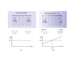
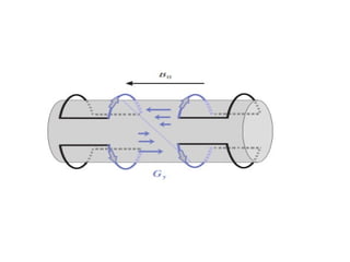
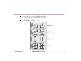
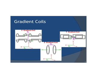
Gradient coils
Saliha hashmi
Lecturer
Post Graduate MRT(Magnetic Resonance
Technology)
In MRI the term Gradient refers to an
additional spatially linear variation in
static field strength in any specified
direction.
• Gradients are loops of wire or thin conductive
sheets on a cylindrical shell lying just inside
the bore of an MR scanner. When current is
passed through these coils a secondary
magnetic field is created. This gradient field
slightly distorts the main magnetic field in a
predictable pattern, causing the resonance
frequency of protons to vary in as a function
of position
• Three sets of gradient coils Gx, Gy and Gz are
used in MRI. They are normally applied for a
short time as a pulse.
• An x gradient will add or subtract from the
magnitude of static field in x direction.
• It is these sets of gradients that gives MRI its
three dimensional capability.
• In a standard cylindrical magnet, such as
superconducting system, the direction of the
bore is termed as z axis, the left right direction
is termed as x axis and the top-bottom
direction is termed as y axis.
Z Axis Gradient
• The z gradient can be
generated through the
use of single pair of
coils with counter
rotating current known
as Maxwell pair.
• It is named in honour of the
Scottish physicist
James Clerk Maxwell.
Y and x axis gradient
• Gy can be generated by using Golay
configuration comprising four coils on the
surface of cylindrical former with the current
producing a quadrapolar magnetic field.
• Gx can be generated using an identical set of
golay coil rotated through 90 degree.
• The design for transverse gradients used in cylindrical MR
magnets is based on a "double-saddle" coil configuration
originally described in 1958 by Marcel Golay.
• The strength of the gradient or how rapidly
the field changes over distance is measured in
milli tesla per meter (mT/m)
Summery
• Gradient coils are used to produce deliberate
variations in the main magnetic field (B0).
There are three sets of gradient coils, one for
each direction. The variation in the magnetic
field permits localization of image slices as
well as phase encoding and frequency
encoding. The set of gradient coils for the z
axis are Helmholtz pairs, and for the x and y
axes, paired saddle coil
Gradient classification according
function
• In MR system gradients are used primarily for
3 main functions.
1. Slice selective gradient
2. Phase encoding gradient
3. Frequency encoding gradient
Slice selective gradient
• It refers to selective excitation of spins within
an imaging volume in any specified direction.
• So slice selection or selective excitation is the
process whereby MR signal is restricted to a 2
dimensional slab within the patient. The
position, width and orientation of the slice
can be controlled by the operator.
• In selective excitation we apply a specially
designed RF pulse at the same time as a
gradient.
• The presence of the gradient causes the
resonance frequency to vary in the position as
a gradient direction.
• Then we send an RF pulse of narrow
bandwidth.
• If the required frequency is present with the
RF bandwidth resonance will happen and
proton will be excited
• If the required frequency is not present within
the RF bandwidth no resonance will happen.
• The orientation of the slice can be varied by
using a physically different gradient axis.
• By applying Gz we get transeverse slice
• By applying Gy we get coronal slice.
• For the sagittal slices we apply Gx.
• The slice thickness may be reduced by either
increasing the gradient of the magnetic field or
decreasing the RF (or transmit) bandwidth.
• A thinner slice produces better anatomical
detail.
• A typical slice thickness is 2–10 mm.
RF Coils
RF coils are the "antenna" of the MRI system
that broadcasts the RF signal to the patient
and/or receives the return signal. RF coils can
be receive-only, in which case the body coil is
used as a transmitter or transmit and receive
(transceiver)
• RF coils create the B1 field which rotates the net magnetization in a
pulse sequence. They also detect the transverse magnetization as it
precesses in the XY plane. RF coils can be divided into three general
categories;
• 1) transmit and receive coils,
• 2) receive only coils,
• 3) transmit only coils.
• Transmit and receive coils serve as the transmitter of the B1 fields
and receiver of RF energy from the imaged object. A transmit only
coil is used to create the B1 field and a receive only coil is used in
conjunction with it to detect or receive the signal from the spins in
the imaged object.
• There are many types of imaging coils. Volume
coils surround the imaged object while surface
coils are placed adjacent to the imaged object
• Surface coils are very popular because they are
a receive only coil and have a good signal-to-
noise ratio for tissues adjacent to the coil. In
general, the sensitivity of a surface coil drops
off as the distance from the coil increases
• Surface coils are the simplest design of coil.
They are simply a loop of wire, either circular
or rectangular, that is placed over the region
of interest. The depth of the image of a
surface coil is generally limited to about one
radius. Surface coils are commonly used for
spines, shoulders, TMJ's, and other relatively
small body parts.
• Paired saddle coils are commonly used for
imaging of the knee. These coils provide better
homogeneity of the RF in the area of interest
and are used as volume coils, unlike surface
coils. Paired saddle coils are also used for the x
and y gradient coils. By running current in
opposite directions in the two halves of the
gradient coil, the magnetic field is made
stronger near one and weaker near the other
• The bird cage coil is the most routinely used
volume coil. It is the coil of choice for imaging
the head and brain.
Shielding
• In order to reduce the magnitude and extent
of the fringe field and thus minimize
interaction between the magnet and its
environment, both passive and active
shielding techniques are commonly used.
Passive shielding
• Passive shielding consists of ferromagnetic
material placed outside the magnet.
• Passive shields are generally constructed from
thick plates of soft iron, an inexpensive
material with relatively high magnetic
permeability.
Active shielding
• Active shielding consists of one or more
electromagnetic coils wound on the outside of
the main magnet coil but with opposite field
orientation.
3.Hardware of MRI basic gradient coils .pptx

3.Hardware of MRI basic gradient coils .pptx

  • 1.
    Gradient coils Saliha hashmi Lecturer PostGraduate MRT(Magnetic Resonance Technology)
  • 2.
    In MRI theterm Gradient refers to an additional spatially linear variation in static field strength in any specified direction.
  • 3.
    • Gradients areloops of wire or thin conductive sheets on a cylindrical shell lying just inside the bore of an MR scanner. When current is passed through these coils a secondary magnetic field is created. This gradient field slightly distorts the main magnetic field in a predictable pattern, causing the resonance frequency of protons to vary in as a function of position
  • 5.
    • Three setsof gradient coils Gx, Gy and Gz are used in MRI. They are normally applied for a short time as a pulse. • An x gradient will add or subtract from the magnitude of static field in x direction. • It is these sets of gradients that gives MRI its three dimensional capability.
  • 6.
    • In astandard cylindrical magnet, such as superconducting system, the direction of the bore is termed as z axis, the left right direction is termed as x axis and the top-bottom direction is termed as y axis.
  • 8.
    Z Axis Gradient •The z gradient can be generated through the use of single pair of coils with counter rotating current known as Maxwell pair. • It is named in honour of the Scottish physicist James Clerk Maxwell.
  • 9.
    Y and xaxis gradient • Gy can be generated by using Golay configuration comprising four coils on the surface of cylindrical former with the current producing a quadrapolar magnetic field. • Gx can be generated using an identical set of golay coil rotated through 90 degree. • The design for transverse gradients used in cylindrical MR magnets is based on a "double-saddle" coil configuration originally described in 1958 by Marcel Golay.
  • 12.
    • The strengthof the gradient or how rapidly the field changes over distance is measured in milli tesla per meter (mT/m)
  • 13.
  • 14.
    • Gradient coilsare used to produce deliberate variations in the main magnetic field (B0). There are three sets of gradient coils, one for each direction. The variation in the magnetic field permits localization of image slices as well as phase encoding and frequency encoding. The set of gradient coils for the z axis are Helmholtz pairs, and for the x and y axes, paired saddle coil
  • 16.
  • 17.
    • In MRsystem gradients are used primarily for 3 main functions. 1. Slice selective gradient 2. Phase encoding gradient 3. Frequency encoding gradient
  • 18.
    Slice selective gradient •It refers to selective excitation of spins within an imaging volume in any specified direction. • So slice selection or selective excitation is the process whereby MR signal is restricted to a 2 dimensional slab within the patient. The position, width and orientation of the slice can be controlled by the operator.
  • 19.
    • In selectiveexcitation we apply a specially designed RF pulse at the same time as a gradient. • The presence of the gradient causes the resonance frequency to vary in the position as a gradient direction. • Then we send an RF pulse of narrow bandwidth.
  • 20.
    • If therequired frequency is present with the RF bandwidth resonance will happen and proton will be excited • If the required frequency is not present within the RF bandwidth no resonance will happen.
  • 22.
    • The orientationof the slice can be varied by using a physically different gradient axis. • By applying Gz we get transeverse slice • By applying Gy we get coronal slice. • For the sagittal slices we apply Gx.
  • 23.
    • The slicethickness may be reduced by either increasing the gradient of the magnetic field or decreasing the RF (or transmit) bandwidth. • A thinner slice produces better anatomical detail. • A typical slice thickness is 2–10 mm.
  • 26.
    RF Coils RF coilsare the "antenna" of the MRI system that broadcasts the RF signal to the patient and/or receives the return signal. RF coils can be receive-only, in which case the body coil is used as a transmitter or transmit and receive (transceiver)
  • 27.
    • RF coilscreate the B1 field which rotates the net magnetization in a pulse sequence. They also detect the transverse magnetization as it precesses in the XY plane. RF coils can be divided into three general categories; • 1) transmit and receive coils, • 2) receive only coils, • 3) transmit only coils. • Transmit and receive coils serve as the transmitter of the B1 fields and receiver of RF energy from the imaged object. A transmit only coil is used to create the B1 field and a receive only coil is used in conjunction with it to detect or receive the signal from the spins in the imaged object.
  • 28.
    • There aremany types of imaging coils. Volume coils surround the imaged object while surface coils are placed adjacent to the imaged object • Surface coils are very popular because they are a receive only coil and have a good signal-to- noise ratio for tissues adjacent to the coil. In general, the sensitivity of a surface coil drops off as the distance from the coil increases
  • 29.
    • Surface coilsare the simplest design of coil. They are simply a loop of wire, either circular or rectangular, that is placed over the region of interest. The depth of the image of a surface coil is generally limited to about one radius. Surface coils are commonly used for spines, shoulders, TMJ's, and other relatively small body parts.
  • 30.
    • Paired saddlecoils are commonly used for imaging of the knee. These coils provide better homogeneity of the RF in the area of interest and are used as volume coils, unlike surface coils. Paired saddle coils are also used for the x and y gradient coils. By running current in opposite directions in the two halves of the gradient coil, the magnetic field is made stronger near one and weaker near the other
  • 31.
    • The birdcage coil is the most routinely used volume coil. It is the coil of choice for imaging the head and brain.
  • 33.
  • 34.
    • In orderto reduce the magnitude and extent of the fringe field and thus minimize interaction between the magnet and its environment, both passive and active shielding techniques are commonly used.
  • 35.
    Passive shielding • Passiveshielding consists of ferromagnetic material placed outside the magnet. • Passive shields are generally constructed from thick plates of soft iron, an inexpensive material with relatively high magnetic permeability.
  • 36.
    Active shielding • Activeshielding consists of one or more electromagnetic coils wound on the outside of the main magnet coil but with opposite field orientation.