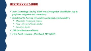
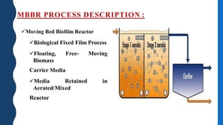
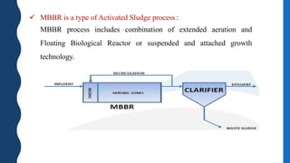
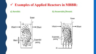
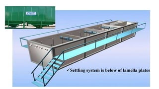
Subject : SOLID FLUID OPERATION
Topic :MOVING BED REACTOR
Sem : 8 th
Prepared by;
Name Enrollment no.
MISHRA JAYBAHADUR M 170143105004
MODI SUARAV K 170143105005
PARMAR KARANSINH B. 170143105007
PATEL JAYANTKUMAR S. 170143105009
SHARMA VIVEK S. 170143105012
VASAVA AVINASHBHAI A. 170143105014
HISTORY OF MBBR
 New Technology (End of 1980s was developed in Trondheim city by
professor odegaard and coworkers)
 Developed in Norway (by caldnes company) commercially :
 Maximize Treatment Volume
 Free- Moving Plastic Media
 Aeration Basin
 500 Installation worldwide
 First North America- Moorhead, MN (2003)
MBBR PROCESS DESCRIPTION :
Moving Bed Biofilm Reactor
Biological Fixed Film Process
Floating, Free- Moving
Biomass
Carrier Media
Media Retained in
Aerated/Mixed
Reactor
 MBBR is a type of Activated Sludge process :
MBBR process includes combination of extended aeration and
Floating Biological Reactor or suspended and attached growth
technology.
 Classification of various major aerobic fixed film
processes used in Wastewater treatment
 Examples of Applied Reactors in MBBR:
a) Aerobic b) Anaerobic/Anoxic
 MBBR can be made in tow ways :
 Reinforced Concrete pools in or on the ground
 or as Pact system that is constructed with steel or coated metal
(steel)
Settling system is below of lamella plates
 Typical Operating Parameters for Moving Bed Biofilm
Reactors (MBBRs):
Variable Range Source
Media
Media Diameter (mm) 7-15 (Andreottola at al., 2000; Odegaard et
al., 2000; Odegaard, 2000)Media Length(mm) 10-15
Specific Surface Area (𝑚2 𝑚3) 160,490-7700
Filling Fraction (%) 60-70
Contact Time (hr) 2-5 (Andreottola at al., 2000; Odegaard et
al., 2000). (Odegaard, 2000)BOD Loading Rate (𝒌𝒈 𝑩𝑶𝑫 𝟕 𝒎 𝟑.𝒅𝒂𝒚) 4-5
Backwashing Never
Maximum Head loss Insignificant
Media:
special Density Media’s is a less of
water (≈ 0.36 𝑔𝑟 𝑐𝑚3).
Media material’s is such as : Polly
Ethylene, Polly urethane and other
high density plastics.
Area of specific surface Bed’s
nearby is 500 cubic meter to a
voluminous Bed volume’s.
Screen plates is installed in end of
reactors for preventing to Media
scape from reactors.
Type of mbbr is package unit
 Final Capacity : 3*200 𝑚3 𝑑
 Initial Capacity : 200 𝑚3 𝑑
 The process tanks constructed in Container dimension, Epoxy Coated
Carbon Steel and suitable to move on standard trailers as and when
required.
 Sludge pumps are installed to take all the sludge from lamella bottom to
Sludge holding tank. Sludge holding tank to be provided in RCC (By
Client) for collection & digestion of sludge. Air will be provided for
digestion of sludge. The digested sludge will be then disposed of by
tanker to suitable site (by Client).
MBBR AERATION SYSTEM:
 The sewage discharged into the Two Stage in series Aeration chambers, each
having certain volume of Floating Media and Set of Air Diffusers.
 The Media inside the Aeration compartment continuously in suspension and
kept rotating in circular motion by Air action directed on them.
 This Media designed to enable biological growth on the surface and to
achieve high rate of oxygen transfer.
 The sewage is than overflow by gravity in to the lamella Clarification
compartment for secondary treatment.
Secondary treatment (settling):
 After the biological reaction, the mixed water flows to the settlement
chamber having tube settler (Lamella) where the activated sludge is
separated from the secondary effluent during a period of quiescent
settlement.
 The secondary effluent discharge from the plant via an overflow weir
and the settled sludge is pumped back to the aeration chamber to
treat more sewage and to maintain the desired F/M ratio.
 The over flow liquid is passed to the Chlorination Tank for tertiary
treatment.

Moving bed reactor

  • 1.
    Subject : SOLIDFLUID OPERATION Topic :MOVING BED REACTOR Sem : 8 th Prepared by; Name Enrollment no. MISHRA JAYBAHADUR M 170143105004 MODI SUARAV K 170143105005 PARMAR KARANSINH B. 170143105007 PATEL JAYANTKUMAR S. 170143105009 SHARMA VIVEK S. 170143105012 VASAVA AVINASHBHAI A. 170143105014
  • 2.
    HISTORY OF MBBR New Technology (End of 1980s was developed in Trondheim city by professor odegaard and coworkers)  Developed in Norway (by caldnes company) commercially :  Maximize Treatment Volume  Free- Moving Plastic Media  Aeration Basin  500 Installation worldwide  First North America- Moorhead, MN (2003)
  • 3.
    MBBR PROCESS DESCRIPTION: Moving Bed Biofilm Reactor Biological Fixed Film Process Floating, Free- Moving Biomass Carrier Media Media Retained in Aerated/Mixed Reactor
  • 4.
     MBBR isa type of Activated Sludge process : MBBR process includes combination of extended aeration and Floating Biological Reactor or suspended and attached growth technology.
  • 5.
     Classification ofvarious major aerobic fixed film processes used in Wastewater treatment
  • 6.
     Examples ofApplied Reactors in MBBR: a) Aerobic b) Anaerobic/Anoxic
  • 7.
     MBBR canbe made in tow ways :  Reinforced Concrete pools in or on the ground  or as Pact system that is constructed with steel or coated metal (steel)
  • 8.
    Settling system isbelow of lamella plates
  • 9.
     Typical OperatingParameters for Moving Bed Biofilm Reactors (MBBRs): Variable Range Source Media Media Diameter (mm) 7-15 (Andreottola at al., 2000; Odegaard et al., 2000; Odegaard, 2000)Media Length(mm) 10-15 Specific Surface Area (𝑚2 𝑚3) 160,490-7700 Filling Fraction (%) 60-70 Contact Time (hr) 2-5 (Andreottola at al., 2000; Odegaard et al., 2000). (Odegaard, 2000)BOD Loading Rate (𝒌𝒈 𝑩𝑶𝑫 𝟕 𝒎 𝟑.𝒅𝒂𝒚) 4-5 Backwashing Never Maximum Head loss Insignificant
  • 10.
    Media: special Density Media’sis a less of water (≈ 0.36 𝑔𝑟 𝑐𝑚3). Media material’s is such as : Polly Ethylene, Polly urethane and other high density plastics. Area of specific surface Bed’s nearby is 500 cubic meter to a voluminous Bed volume’s. Screen plates is installed in end of reactors for preventing to Media scape from reactors.
  • 12.
    Type of mbbris package unit  Final Capacity : 3*200 𝑚3 𝑑  Initial Capacity : 200 𝑚3 𝑑  The process tanks constructed in Container dimension, Epoxy Coated Carbon Steel and suitable to move on standard trailers as and when required.  Sludge pumps are installed to take all the sludge from lamella bottom to Sludge holding tank. Sludge holding tank to be provided in RCC (By Client) for collection & digestion of sludge. Air will be provided for digestion of sludge. The digested sludge will be then disposed of by tanker to suitable site (by Client).
  • 13.
    MBBR AERATION SYSTEM: The sewage discharged into the Two Stage in series Aeration chambers, each having certain volume of Floating Media and Set of Air Diffusers.  The Media inside the Aeration compartment continuously in suspension and kept rotating in circular motion by Air action directed on them.  This Media designed to enable biological growth on the surface and to achieve high rate of oxygen transfer.  The sewage is than overflow by gravity in to the lamella Clarification compartment for secondary treatment.
  • 14.
    Secondary treatment (settling): After the biological reaction, the mixed water flows to the settlement chamber having tube settler (Lamella) where the activated sludge is separated from the secondary effluent during a period of quiescent settlement.  The secondary effluent discharge from the plant via an overflow weir and the settled sludge is pumped back to the aeration chamber to treat more sewage and to maintain the desired F/M ratio.  The over flow liquid is passed to the Chlorination Tank for tertiary treatment.