Download to read offline


![Shri Vile Parle Kelavani Mandal’s Institute of Technology, Dhule
Department of Civil Engineering 24
Prepared
By-
Prof.
Basweshwar
S.
J.
Modulus of sub-grade reaction-
• Westergaard considered the rigid pavement
slab as a thin elastic plate resting on soil sub-
grade, which is assumed as a dense liquid.
• The upward reaction is assumed to be
proportional to the deflection.
• Based on this assumption, Westergaard defined
a modulus of sub-grade reaction K in kg/cm3
given by
K = p
Where, is the displacement level taken as 0.125
cm and p is the pressure sustained by the rigid
plate of 75 cm diameter at a deflection of 0.125
cm.
Relative stiffness of slab to sub-grade-
• A certain degree of resistance to slab
deflection is offered by the sub-grade.
• Slab deflection is direct measurement of the
magnitude of the sub-grade pressure.
• Pressure deformation characteristics of
rigid pavement lead Westergaard to the
define the term radius of relative stiffness l
in cm is given by the equation-
Where, E is the modulus of elasticity of
cement concrete in kg/cm2 (3.0 x 10^5), [mu]
is the Poisson's ratio of concrete (0.15), h is
the slab thickness in cm and K is the modulus
of sub-grade reaction.
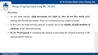
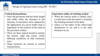
Design of rigid pavement using IRC: 58-2011](https://image.slidesharecdn.com/transportationengineeringm5-230511122120-48295c00/85/TRANSPORTATION_ENGINEERING_M5-pdf-24-320.jpg)


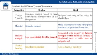
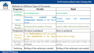
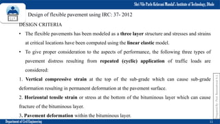
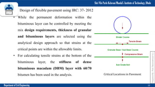
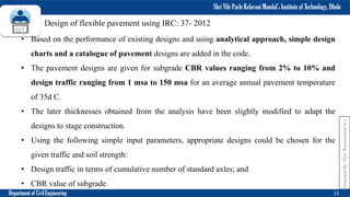
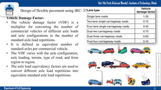
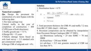
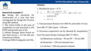
This document outlines the design of flexible pavements using IRC: 37-2012. It discusses the scope, design criteria, design traffic considerations including vehicle damage factors and distribution, and provides pavement thickness design charts. It also describes the composition of flexible pavements including materials for the sub-base, base and bituminous surfacing layers. Two numerical examples of designing flexible pavements for given traffic and soil conditions are included using the IRC method.