Download to read offline
![IJSRD - International Journal for Scientific Research & Development| Vol. 2, Issue 08, 2014 | ISSN (online): 2321-0613
All rights reserved by www.ijsrd.com 348
Modified LAEEBA Routing In WBAN
Sheth Mahammed Ovesh I1
Assoc. Prof. Ajay Kumar Sharma2
1
Associate Professor
1,2
Department of Computer Science & Engineering
1,2
Geetanjali Institute of Technical Studies, Udaipur
Abstract— This paper modifies the LAEEBA protocol to
enhance the performance of the protocol. Eight sensor
nodes are deployed on a human body; having equal power
and computation capabilities. Sink node is placed at waist.
Different nodes are used to measure various activities like
Glucose level etc. In the LAEEBA protocol all the nodes are
active at every time, but the total usage period of few nodes
is very less depending upon the disease covered. This leads
to the wastage of the energy. This work uses the Sleep state
to save the energy. The sink node will remain active all the
times and the other node are in the sleep state. The node
which gets selected for the transmission will change its state
to the active state; other nodes will remain in the sleep state.
The simulation results show that the proposed technique is
better than the existing technique. The comparison is done
by using the PDR, E2E Delay and throughput. The delay
gets decreased and the throughput gets increased. The PDR
in the proposed algorithm is greater than the existing
algorithm so the proposed algorithm is better than the
existing algorithm.
Keywords: WBAN, LAEEBA, PDR
I. INTRODUCTION
A WBAN consists of several sensors and possibly actuators
equipped with a radio interface. Each WBAN has a sink or
personal server such as a PDA, that receives all information
from the sensors and provides an interface towards other
networks or medical staff. Connecting health monitoring
sensors wirelessly improves comfort for patients but induces
a number of technical challenges like coping with mobility
and the need for increased reliability. The main use of
sensor networks can be found in the area of wearable health
monitoring. Carefully placing sensors on the human body
and wirelessly connecting them to monitor physiological
parameters like heartbeat, body temperature, motion et
cetera is a promising evolution This system can reduce the
enormous costs of patients in hospitals as monitoring can
occur real-time, over a longer period and at home.
An important requirement in WBANs is the energy
efficiency of the system. The sensors placed on the body
only have limited battery capacity or can scavenge only a
limited amount of energy from their environment.
Consequently, in order to increase the lifetime of the
network, energy efficient measures needs to be taken. From
that point of view, several researchers are developing low
power sensors and radios. Another possibility is the design
of optimized network protocols to lower the energy
consumption while satisfying the other requirements [1].
II. WBAN ARCHITECHTURE
Figure 1 shows secure 3-level WBAN architecture for
medical and non-medical applications. Level 1 contains in-
body and on-body BAN Nodes (BNs) such as
Electrocardiogram (ECG) – used to monitor electrical
activity of heart, Oxygen saturation sensor (SpO2) –used
to measure the level of oxygen, and Electromyography
(EMG) – used to monitor muscle activity [2].
Level 2 contains a BAN Network Coordinator
(BNC) that gathers patient’s vital information from the
BNs and communicates with the base-station. Level 3
contains a number of remote base-stations that keep
patient’s medical/non-medical records and provides
relevant (diagnostic) recommendations. The traffic is
categorized into on demand, emergency, and normal
traffic. On-demand traffic is initiated by the BNC to
acquire certain information. Emergency traffic is initiated
by the BNs when they exceed a predefined threshold.
Normal traffic is the data traffic in a normal condition with
no time critical and on-demand events.
Fig. 1: Secure 3-level WBAN architecture for medical and
non-medical applications
The normal data is collected and processed by the
BNC. The BNC contains a wakeup circuit, a main radio,
and a security circuit, all of them connected to a data
interface. The wakeup circuit is used to accommodate on-
demand and emergency traffic. The security circuit is used
to prevent malicious interaction with a WBAN.
III. LOW DUTY CYCLE MAC PROTOCOL
Low Duty Cycle MAC protocol for WBANs is designed in
[5]. This protocol consist, analog to digital conversion is
performed by slave nodes while the other complex tasks
such as digital signal processing is carried out at MN. These
MNs are supposed to be less power than slave nodes.
Protocol introduces the concept of Guard Time (Tg) to avoid
overlapping between consecutive time slots. When T frames
a Network Control (NC) packet is used for general network](https://image.slidesharecdn.com/ijsrdv2i8212-150923115555-lva1-app6892/75/Modified-LAEEBA-Routing-in-WBAN-1-2048.jpg)
![Modified LAEEBA Routing In WBAN
(IJSRD/Vol. 2/Issue 08/2014/079)
All rights reserved by www.ijsrd.com 349
information power saving is achieved by using effective
TDMA strategy.
This protocol is energy efficient because it sends
data in short bursts. Using TDMA strategy, this protocol
effectively overcomes the collision problem. This allows
monitoring patient's condition and can reduce the work load
on medical staff, while keeping minimum power usage.
TDMA strategy is used, and it is found that TDMA is more
suitable for static type of networks with a limited number of
sensors generating data at a fixed rate therefore, this
protocol may not respond well in a dynamic topology.
Duty cycle is one of the most widely used
techniques in MAC protocols. The Duty cycle MACs use
radio ON/OFF technique to reduce idle listening [6]. Duty
cycle MACs can be broadly classified into two major
categories:
Fixed duty cycle MACs
Adaptive duty cycle MACs
A fixed duty cycle MAC uses fixed length period.
Some of the earliest MAC protocols (e.g., S-MAC)are based
on the fixed duty cycle concept. The adaptive duty cycling
MACs such as T-MAC [7] and Wise MAC, the
sleep/wakeup time of sensor nodes is adaptively determined.
And they are more effective in saving power than the fixed
non-adaptive MAC protocols. The Duty cycle MACs can be
further classified as follows:
Synchronous duty cycle MACs
Asynchronous duty cycle MACs
Synchronous MACs need time synchronization
before data communication while asynchronous MACs such
as B-MAC, X-MAC are independent of such a requirement.
Though these protocols are effective, they have their own
disadvantages. It remains to be seen if they can satisfy the
application requirement of BAN.
The duty cycle-based MACs have to deal with
issues such as idle state power consumption, collision,
overhearing of packets that are not intended to it and packet
overheads. More effective way is to use an on-demand
mechanism employing the wakeup radio. The additional
ultra-low power receiver is attached to the sensor nodes that
can help save a significant amount of power by minimizing
the idle listen period for the main radio.
IV. LAEEBA ROUTING
The limited number of nodes in a WBAN environment gives
us an opportunity to relax constraints in routing protocols.
Considering these constrains in mind, existing have tried to
improve the network life-time of the network; energy of the
network as well as the path loss of the link being established
between the nodes. The path selection is done in such a way
that a path with minimum number of hops for data
transmission, direct communication for emergency data and
multi hop for normal data delivery. Thus, relay nodes can
easily forward the received data to sink due to higher energy
levels. Additionally, it analyzes their protocol for cross layer
application in terms of path loss and network life-time.
A. System Model
In existing model, sink is placed at center of the human
body. Since WBANs are heterogeneous networks, then
placement of nodes on human body is an issue. Eight sensor
nodes are deployed on a human body; having equal power
and computation capabilities. Sink node is placed at waist.
Node 1 is the sensor for detecting ECG while node 2 is the
sensor for detecting Glucose. These two nodes transmit data
directly to sink. Rests of the nodes are transmitting data to
the sink through other nodes acting as relay. Figure 2 below
shows the schematic diagram for existing protocol
Fig. 2: Schematic Diagram for LAEEBA Protocol
B. Initialization Phase
Three different types of tasks are performed in this phase;
first each node is informed with its neighbors, the location
of sink on the body is identified and all the possible routes
to sink are also evaluated. The sensors update their location
of neighbors and sink when each node broadcasts an
information packet containing its node ID, its own location
and its energy status.
C. Next-Hop Selection Phase
In this section, we present selection criteria for a node to
become parent node or forwarder. To balance energy
consumption among sensor nodes and to trim down energy
consumption of network, LAEEBA protocol elects new
forwarder in each round. The sink node knows the ID,
distance and residual energy status of all its constituent
nodes. It computes the cost function of all nodes and
transmits this value to all members. On its basis, each node
decides whether to become a forwarder node or not. If i is
number of nodes than cost function c(i) of i nodes is
computed as follows:
√
(4.1)
Where, in equation (4.1). d(i) is the distance
between the node i and sink, E(i) is the residual energy of
node i and is calculated by subtracting the current energy of
node from its initial energy. A node with minimum cost
function is preferred as a forwarder. All neighbor nodes then
stick to the forwarder node and transmit their data to it.
Forwarder node aggregates data and transfers to sink. This
node has maximum residual energy and minimum distance
to sink; therefore, it consumes minimum energy to forward
data to sink. Nodes like 1 and 2 for ECG and Glucose
monitoring communicate direct to sink and do not
participate in forwarding data.](https://image.slidesharecdn.com/ijsrdv2i8212-150923115555-lva1-app6892/75/Modified-LAEEBA-Routing-in-WBAN-2-2048.jpg)
![Modified LAEEBA Routing In WBAN
(IJSRD/Vol. 2/Issue 08/2014/079)
All rights reserved by www.ijsrd.com 351
LAEEBA
MLAEEBA
LAEEBA
MLAEEBA
LAEEBA
MLAEEBA
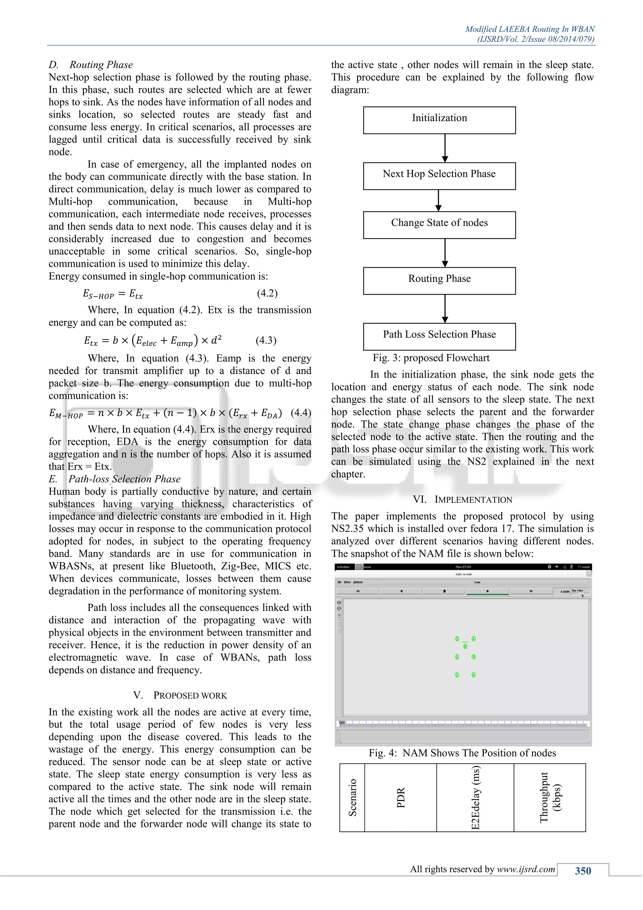
1 45.51 54.03 0.9942 0.992 19.07 21.22
2 45.61 55.97 0.9941 0.992 20.80 20.16
3 46.27 54.43 0.9941 0.992 10.61 20.45
4 46.66 58.10 0.9921 0.994 7.10 20.22
Table 1: Performance Parameter Between Laeeba And
Mlaeeba
Fig. 5: Comparison of PDR between LAEEBA and
MLAEEBA
Fig. 6: Comparison of E2E Delay between LAEEBA and
MLAEEBA
Fig. 7: Comparison of throughput between LAEEBA and
MLAEEBA
VII. CONCLUSION
The results show that the proposed technique is better than
the existing technique. The comparison is done by using the
PDR, E2E Delay and throughput. The delay gets decreased
and the throughput gets increased. The PDR in the proposed
algorithm is greater than the existing algorithm so the
proposed algorithm is better than the existing algorithm. In
future, this work can be extended in terms of security. This
work is not capable to handle the faulty node, this procedure
can be added to extended the work.
REFERENCES
[1] Latre, B., Braem, B., Moerman, I., Blondia, C.,
Reusens, E., Joseph, W., & Demeester, P. (2007,
August). A low-delay protocol for multihop wireless
body area networks. In Mobile and Ubiquitous
Systems: Networking & Services, 2007. MobiQuitous
2007. Fourth Annual International Conference on (pp.
1-8). IEEE.
[2] Saleem, S., Ullah, S., & Yoo, H. S. (2009). On the
Security Issues in Wireless Body Area Networks.
JDCTA, 3(3), 178-184..
[3] VishwaGoudar and MiodragPotkonjak, “Energy-
Efficient Sampling Schedules for Body Area
Networks”978-1-4577-1767-3/12/$26.00 ©2012
IEEE.
[4] IlkerDemirkol, CemErsoy, and FatihAlagöz, “MAC
Protocols for Wireless Sensor Networks: A
Survey”,IEEE Communications Magazine • April
2006.
[5] Marinkovic, S.J. and Popovici, E.M. and Spagnol, C.
and Faul, S. and Marnane, W.P., 2009. Energy-
efficient low duty cycle MAC protocol for wireless
body area networks: IEEE.
[6] Moshaddique Al Ameen, NiamatUllah, “A power
efficient MAC protocol for wireless bodyarea
networks”Al Ameen et al. EURASIP Journal on
Wireless Communications and Networking 2012,
2012:33.
[7] T van Dam, K Langendoen, An adaptive energy-
efficient MAC protocol for wireless sensor networks,
in Proceedings of the First ACM Conference on
Embedded Networked Sensor Systems, Los Angeles,
CA, USA, pp. 171–180 (November 2003).
0
20
40
60
80
1 2 3 4
PDR
Scenario
LAEEBA
MLAEEBA
0.99
0.991
0.992
0.993
0.994
0.995
1 2 3 4
E2EDelay
Scenario
LAEEBA
MLAEEBA
0
5
10
15
20
25
1 2 3 4
Throughput
Scenario
LAEEBA
MLAEEBA](https://image.slidesharecdn.com/ijsrdv2i8212-150923115555-lva1-app6892/75/Modified-LAEEBA-Routing-in-WBAN-4-2048.jpg)

This document presents a modified Laeeba routing protocol designed to enhance the performance and energy efficiency of Wireless Body Area Networks (WBANs) by reducing the energy wastage during sensor node operation. By implementing a sleep state for inactive nodes and activating only the selected nodes for data transmission, the proposed technique demonstrates improved packet delivery rate, reduced end-to-end delay, and increased throughput compared to the existing protocol. The findings are validated through simulations, indicating the effectiveness of the modifications in optimizing the network's performance.