Download to read offline
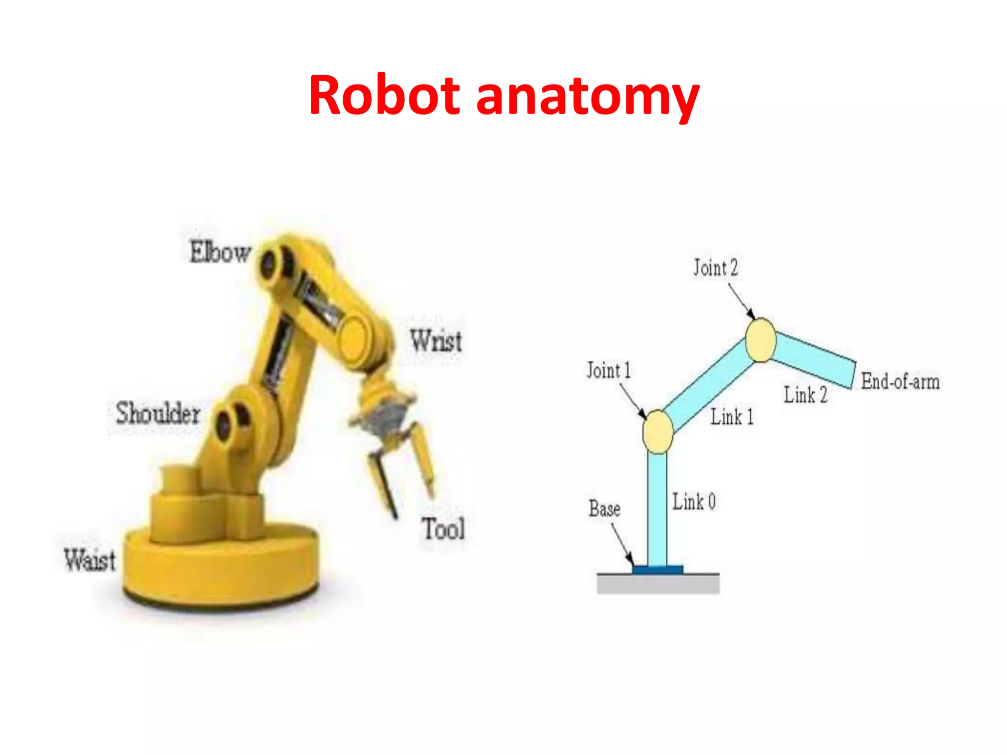
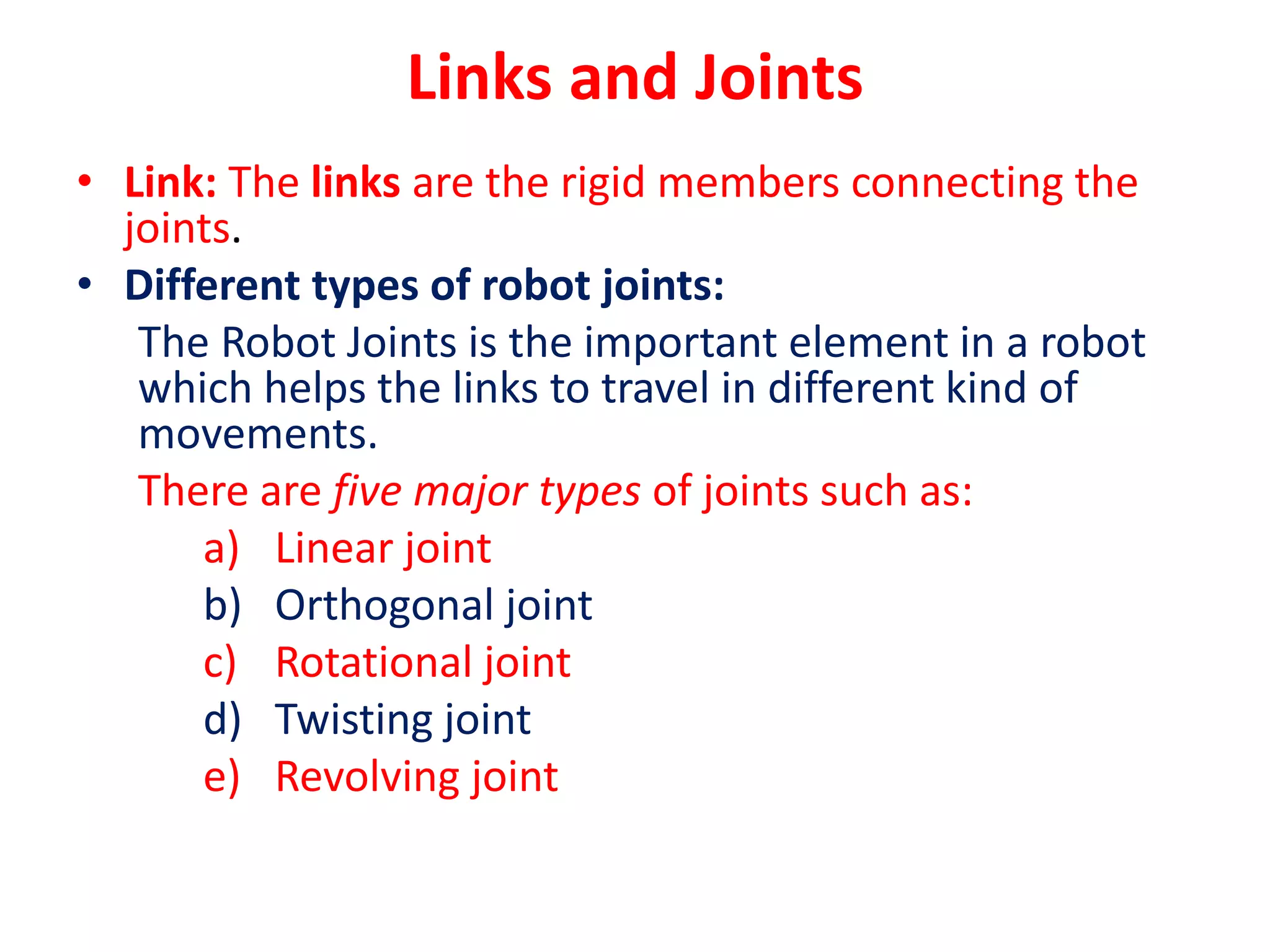
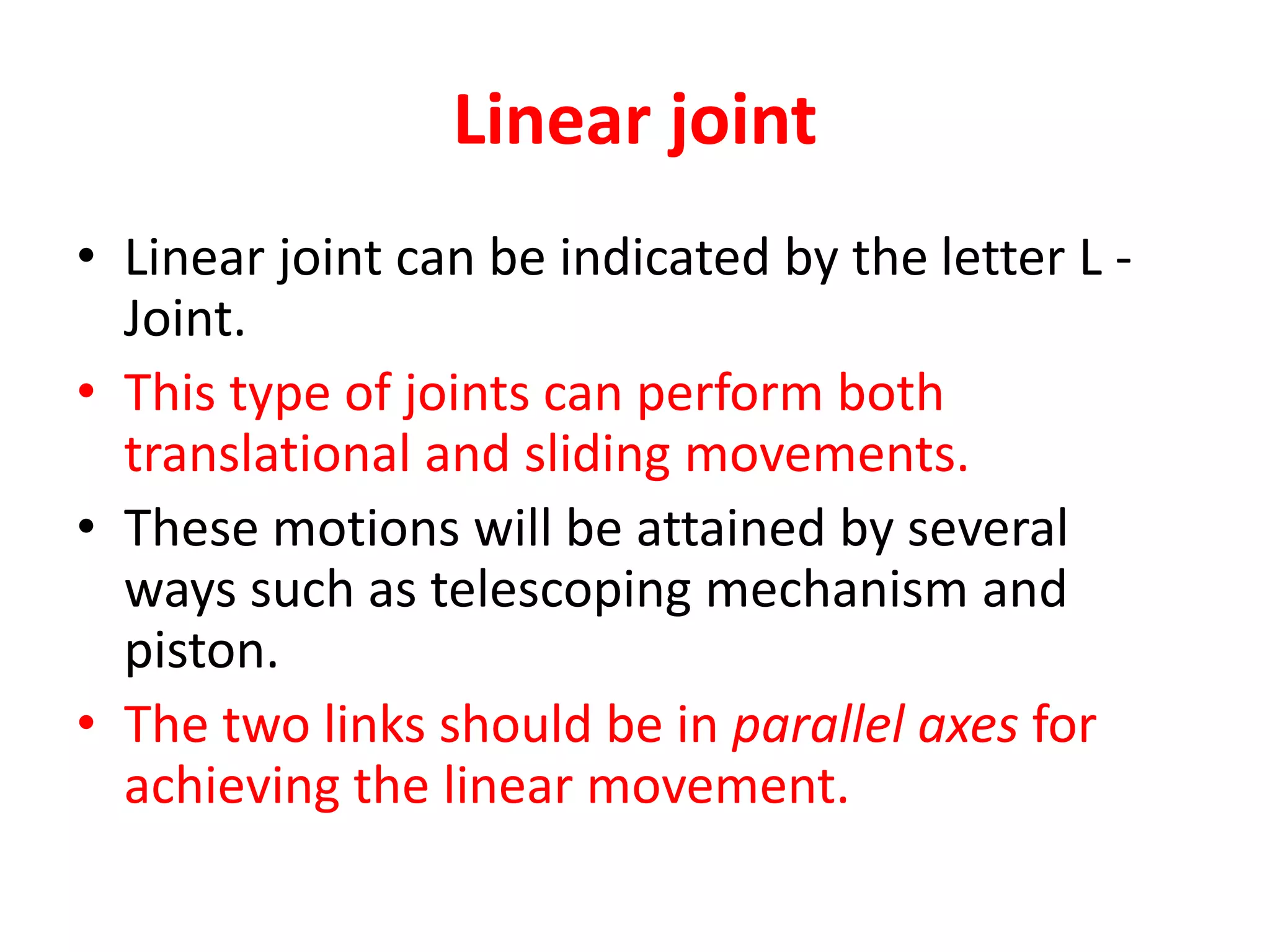
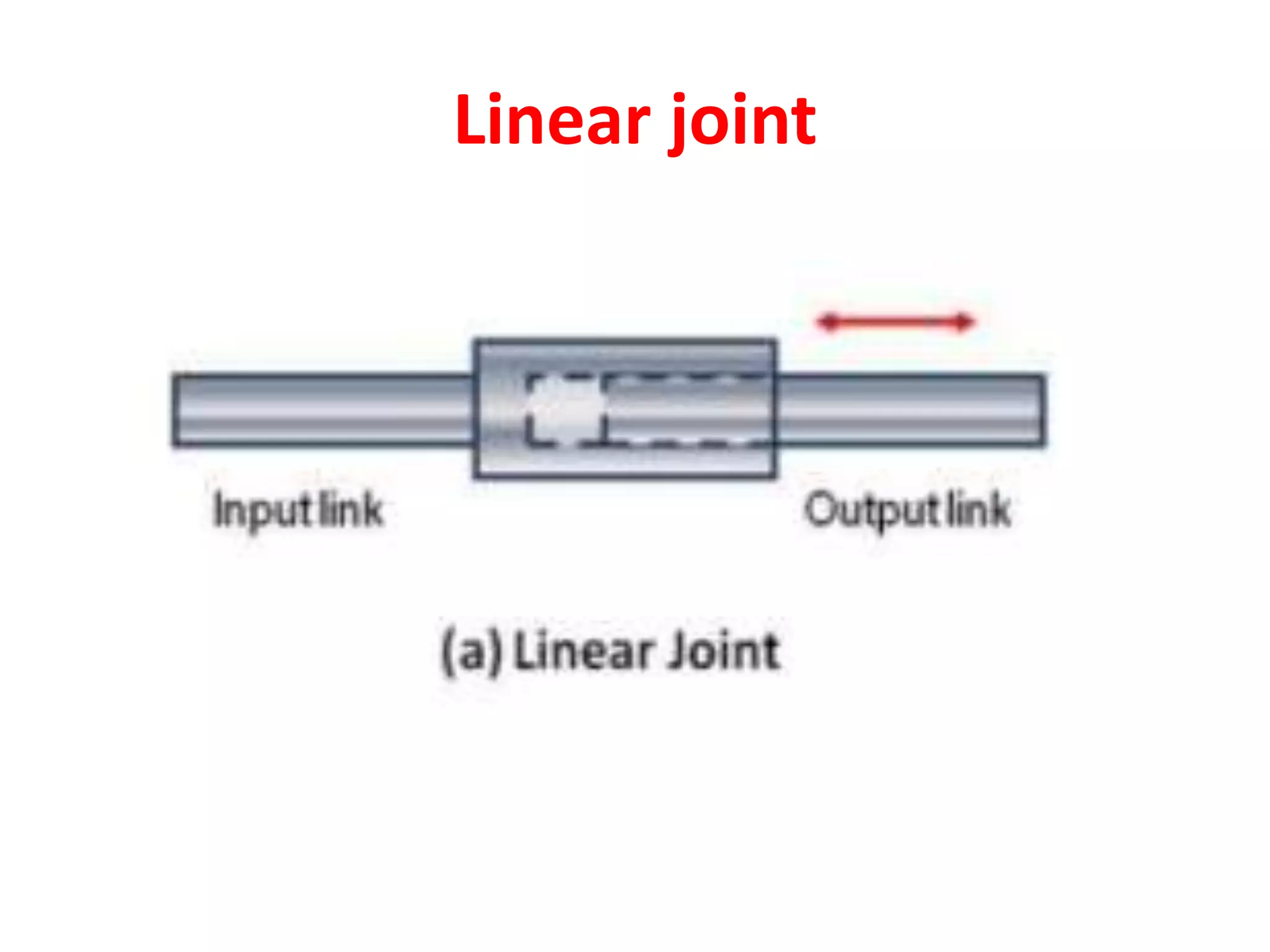
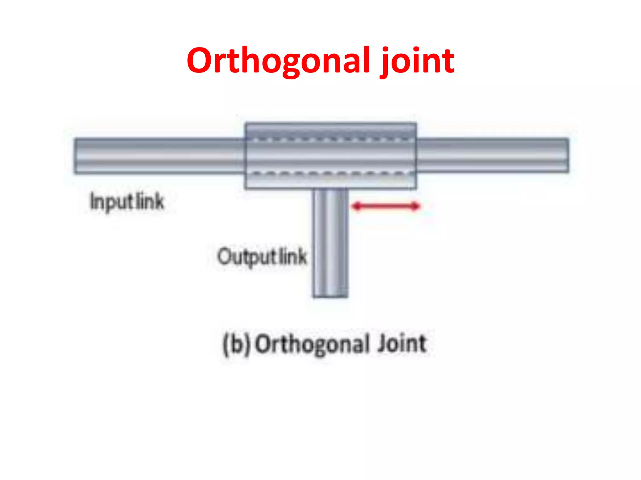
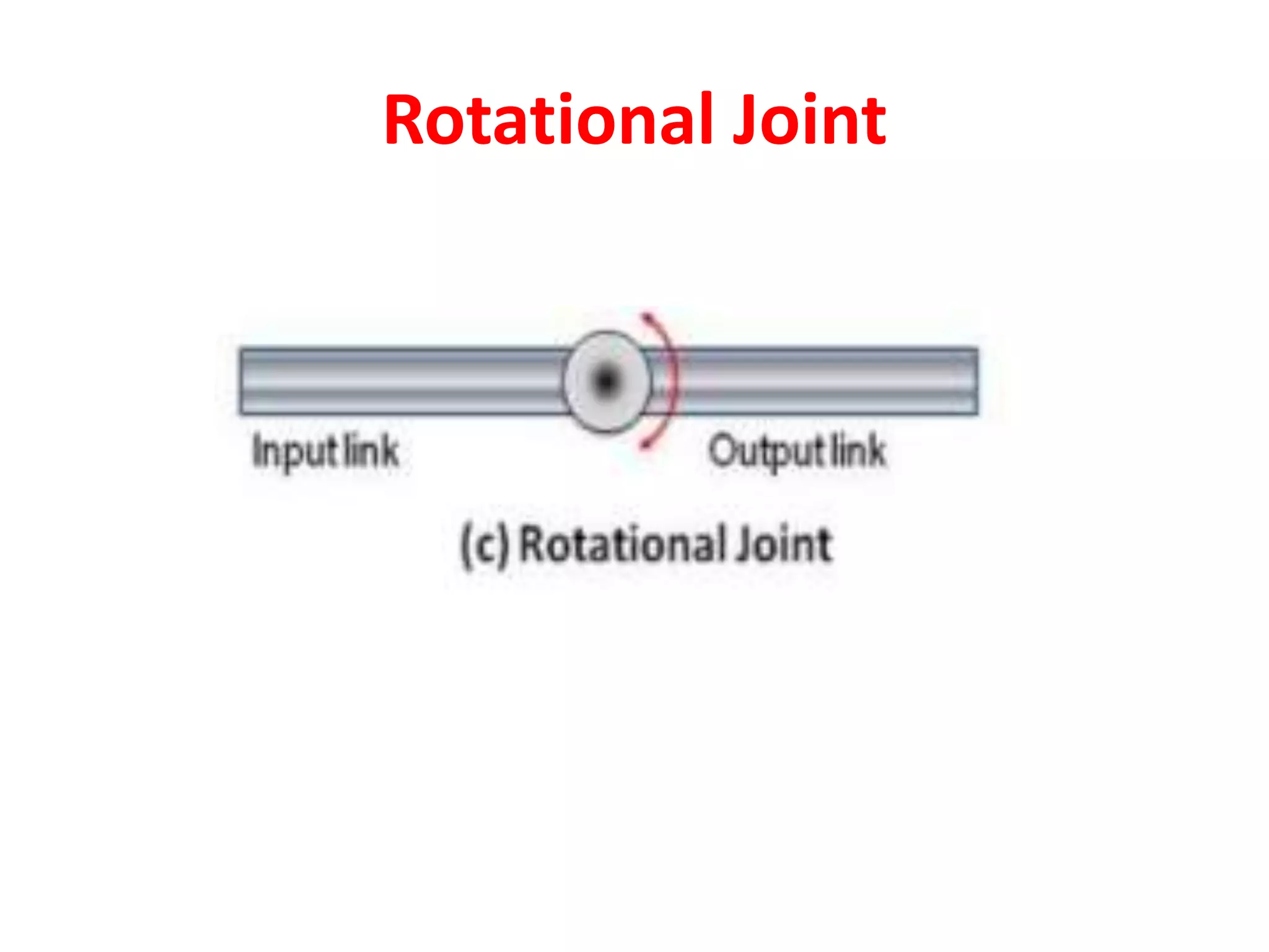
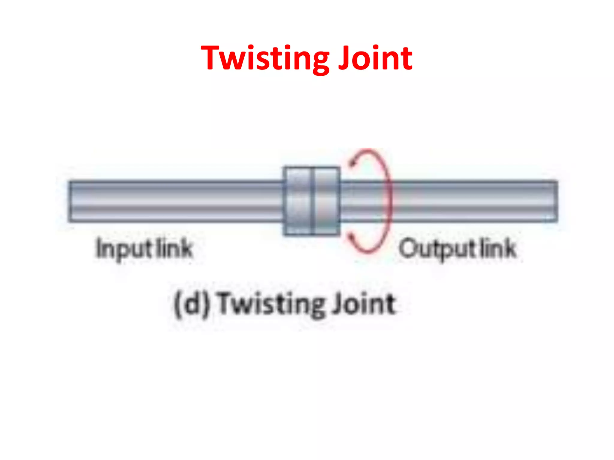
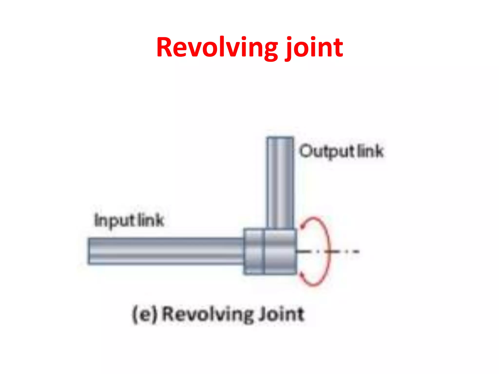
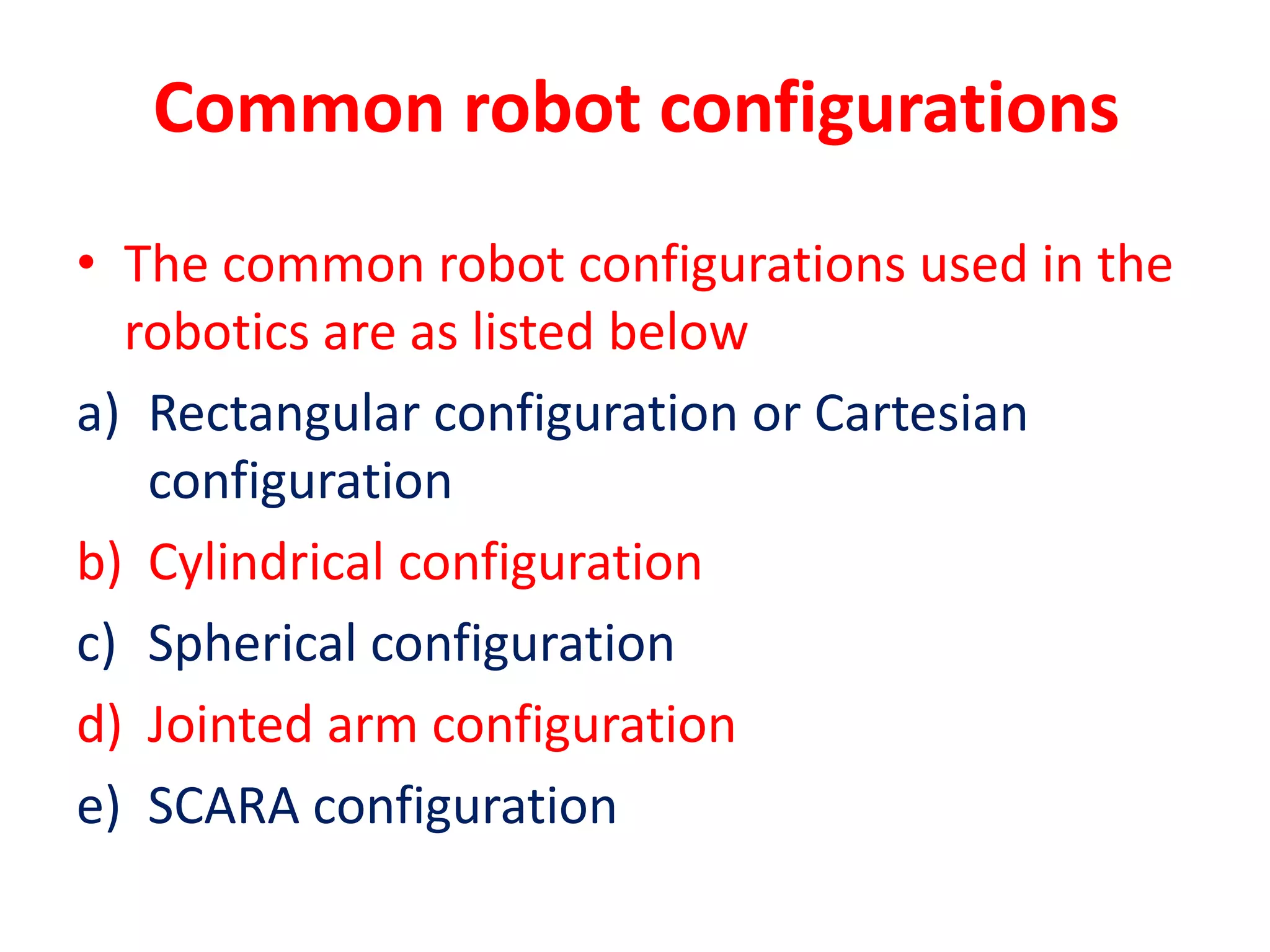
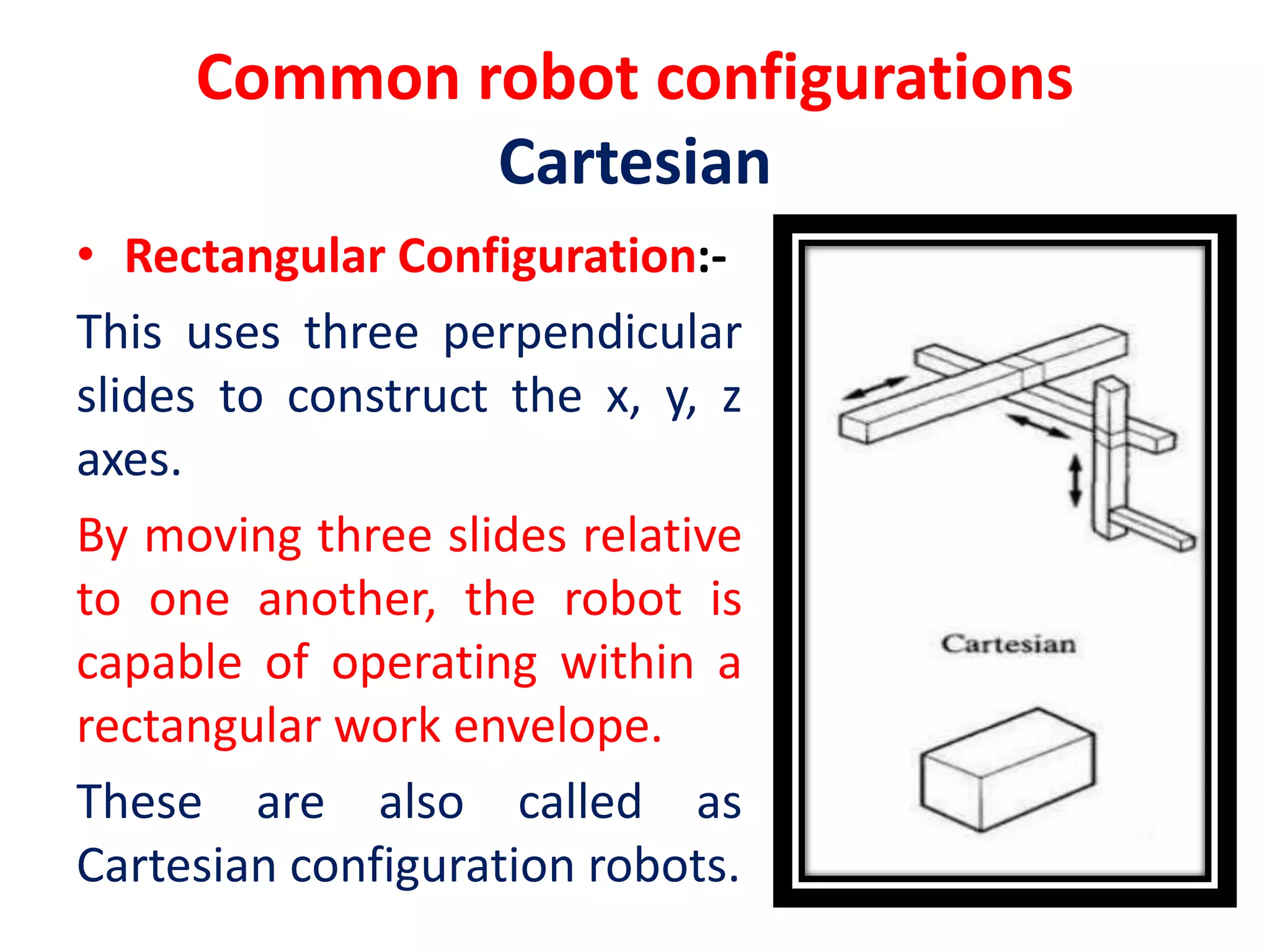

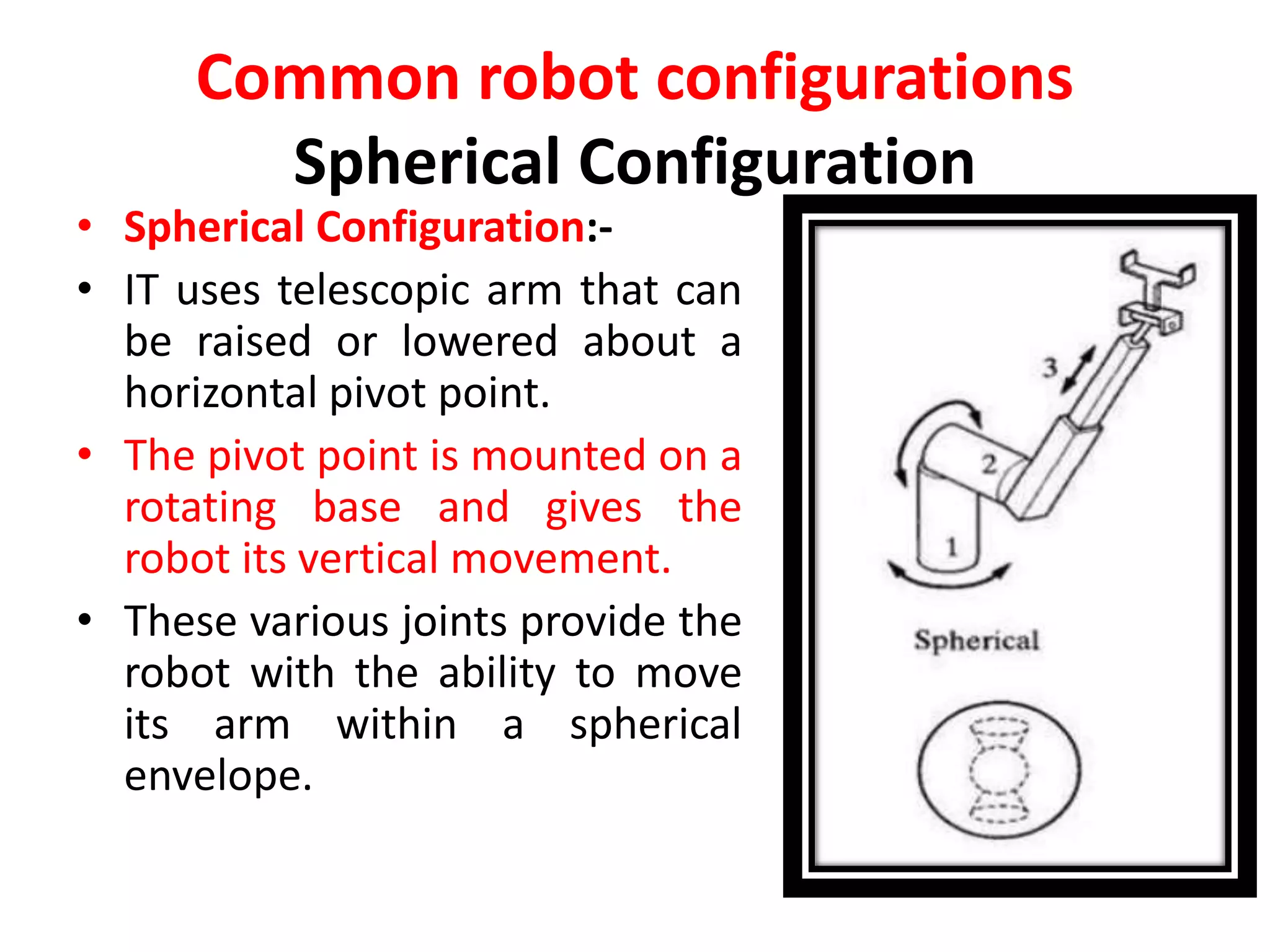
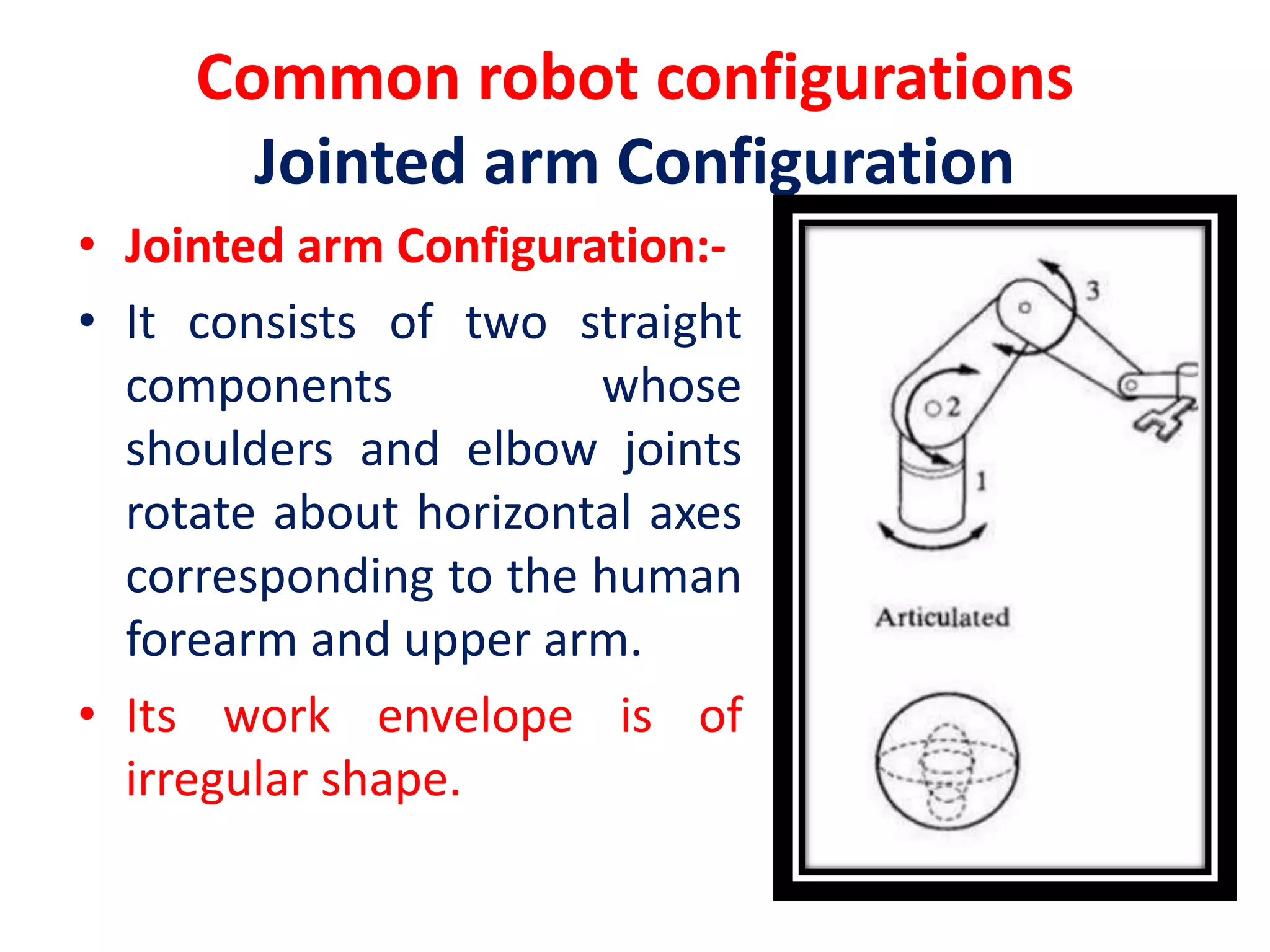
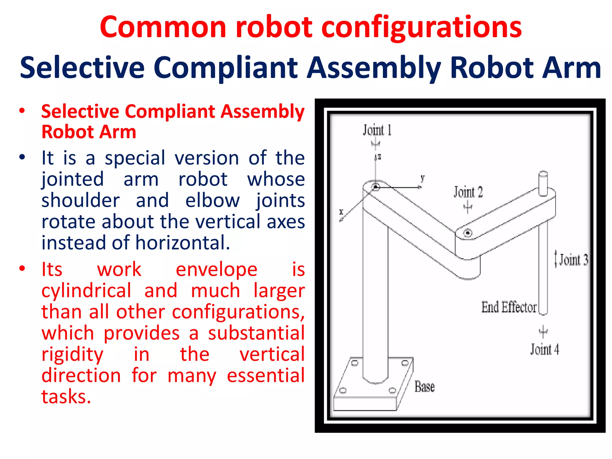
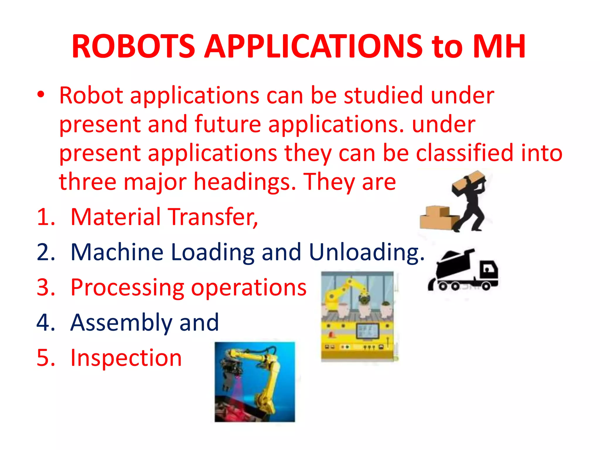


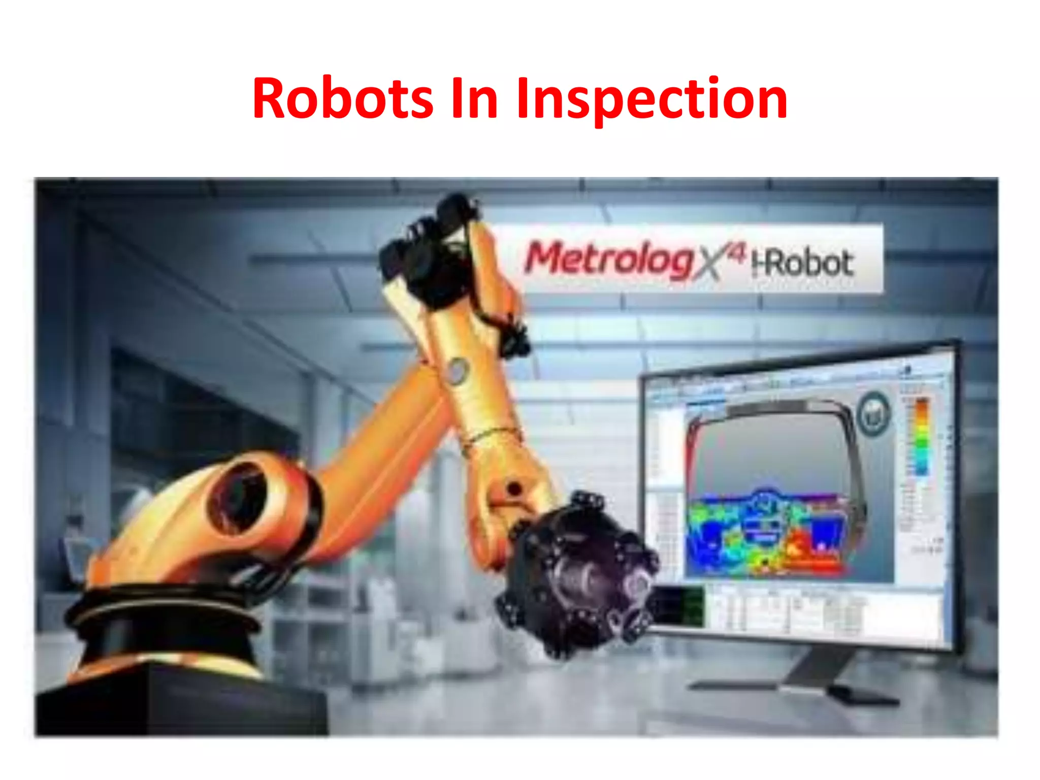

This document discusses robot anatomy and configurations as well as applications of robots. It describes the different types of robot joints including linear, orthogonal, rotational, twisting, and revolving joints. The common robot configurations of Cartesian, cylindrical, spherical, jointed arm, and SCARA are explained. Applications of robots discussed include material handling, processing, assembly, and inspection. Material handling involves tasks like material transfer, machine loading/unloading. Assembly applications include operations like screwing, insertion, and small component assembly. Robots are also used for non-destructive inspection using probes, cameras, and 3D measurements.