Download as PDF, PPTX

![© 2017 MIPI Alliance, Inc.
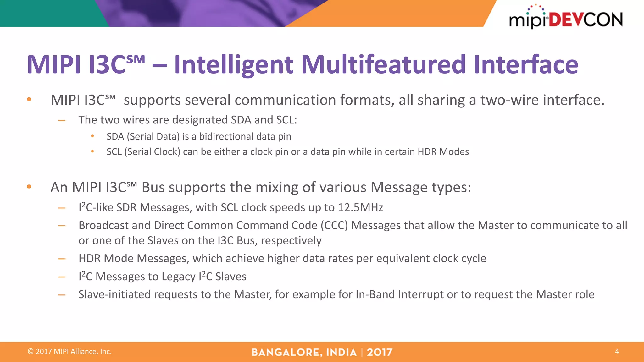
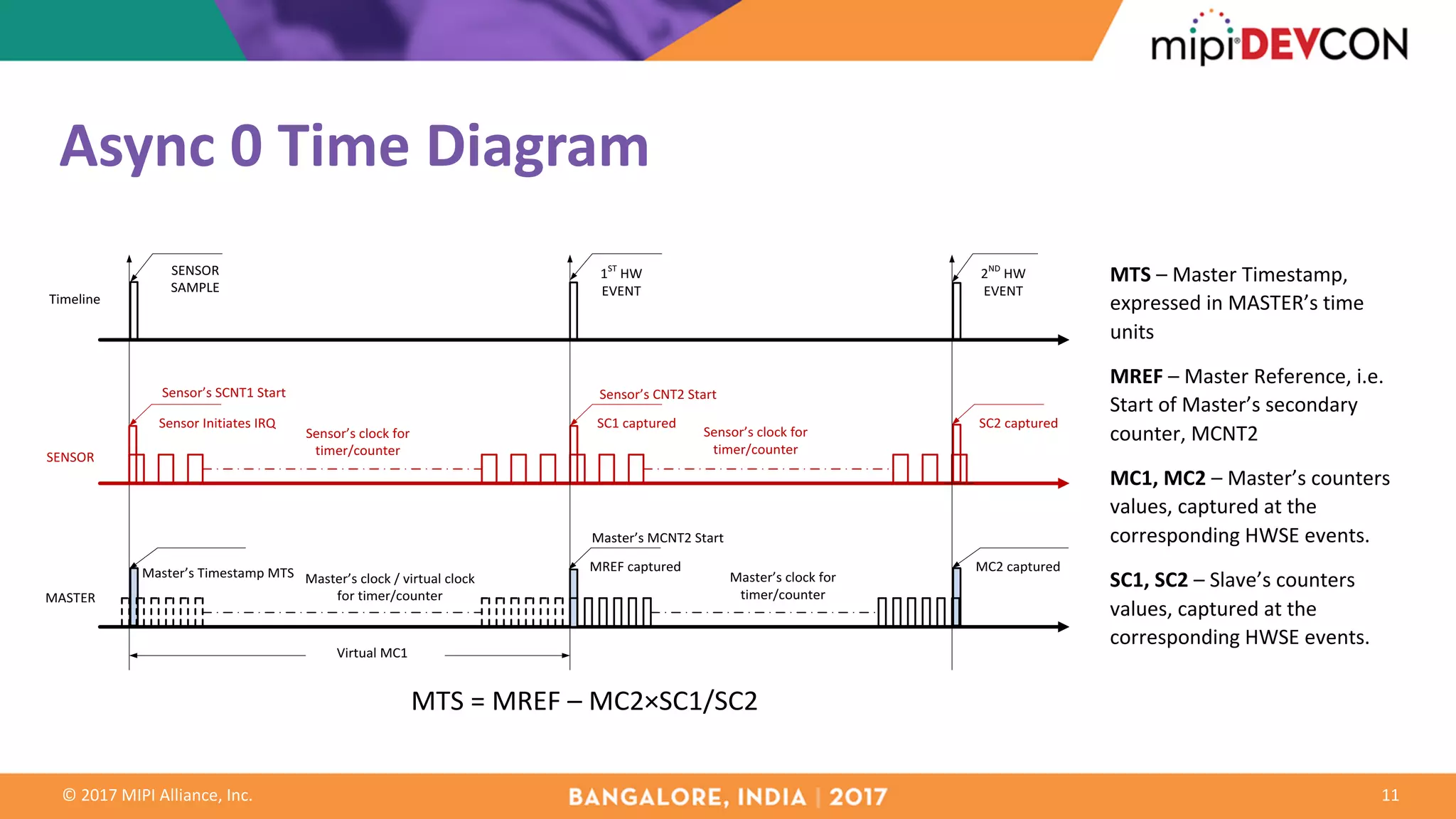
Synchronous Systems and Events
7
S_RED
ST+DT
S_GREEN S_BLUE
SENSORS READ
NOT IN SYNC
SYNC Tick [ST] and
Delay Time [DT]
in-band, via I3C bus
ALL READ
IN SYNC
Sequence Repetition Period
Adjustable [0.2 ; 5 sec], 1 sec nominal
Sequence repeats
T_Ph start T_Ph start
SENSORS DATA
NOT IN SYNC
ALL DATA
IN SYNC
ST+DT
DT
Sensors sample Sensors sample Sensors sample Sensors sample Sensors sample Sensors sample](https://image.slidesharecdn.com/bangalore-qualcomm-mipi-i3c-interface-advanced-features-171110191351/75/MIPI-DevCon-Bangalore-2017-MIPI-I3C-Interface-Advanced-Features-7-2048.jpg)
![© 2017 MIPI Alliance, Inc.
Synchronous – Multiple Transactions
8
Sequence Repetition Period
Adjustable [0.2 ; 5 sec], 1 sec nominal
I3C messages, on the bus
Some I3C transactions START condition is used
by the Slaves (sensors) for adjusting their
(sensors’) internal timers
Sequence repeats
ST&DT to next ST&DT delay
Adjustable [0.2 ; 5 sec], 1 sec nominal
Each ST&DT instantiation includes Timer Error
Correction data
ST&DT
Polling
Polling or
something
else
I3C START
Sensors
Sample
unsynchronized
ST if validated
by DT
I3C START I3C START I3C START
Polling or
something
else
ST&DT
Polling
T_Ph start, calculated
from ST and DT
ST if validated
by DT
T_Ph start, calculated
from ST and DT
Refresh/Adjust
Sensor’s Timer
DT between ST
and T_Ph Start
Sync Tick [ST] &
Delay Time [DT]
Sync Tick [ST] &
Delay Time [DT]
Sensors
Sample
unsynchronized
Sensors
Sample
unsynchronized
Sensors
Sample
in sync
Sensors
Sample
in sync
Sensors
Sample
unsynchronized
Sensors
Sample
in sync
Sensors
Sample
in sync](https://image.slidesharecdn.com/bangalore-qualcomm-mipi-i3c-interface-advanced-features-171110191351/75/MIPI-DevCon-Bangalore-2017-MIPI-I3C-Interface-Advanced-Features-8-2048.jpg)
![© 2017 MIPI Alliance, Inc.
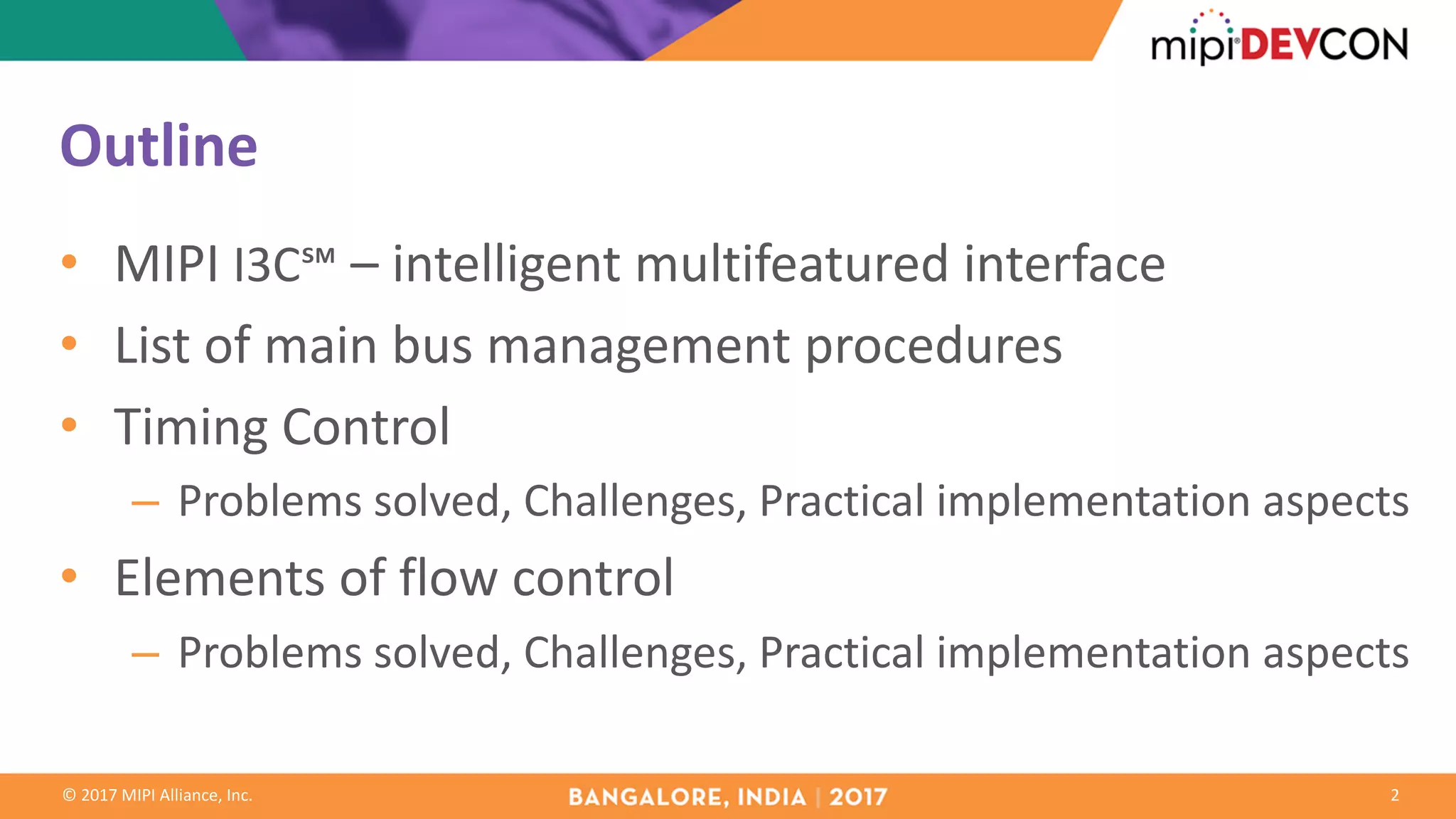
Synchronous – Common Command Codes
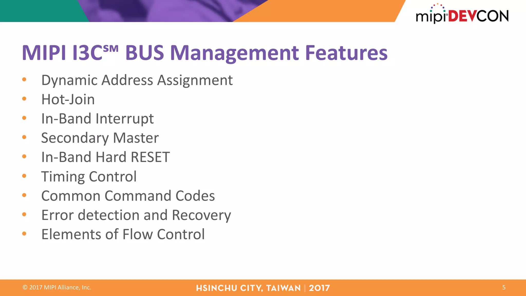
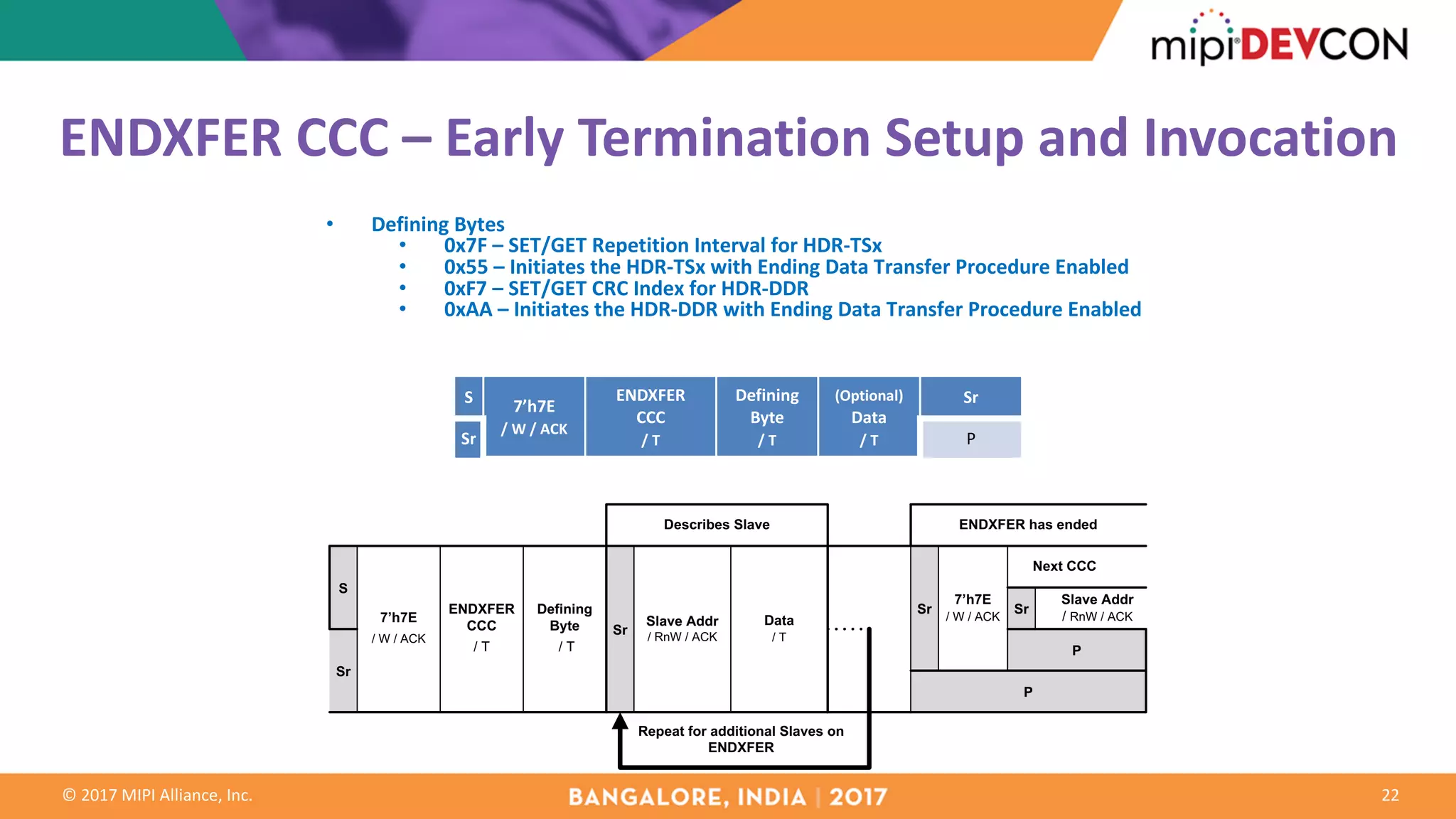
• SETXTIME CCC
• Configuration messages
– ODR (Output Data Rate)
– TPH (Procedure Repetition Time)
– TU (Time Unit)
• Run Time messages
– SYNC Tick [ST]
– Delay Time [DT]
9](https://image.slidesharecdn.com/bangalore-qualcomm-mipi-i3c-interface-advanced-features-171110191351/75/MIPI-DevCon-Bangalore-2017-MIPI-I3C-Interface-Advanced-Features-9-2048.jpg)
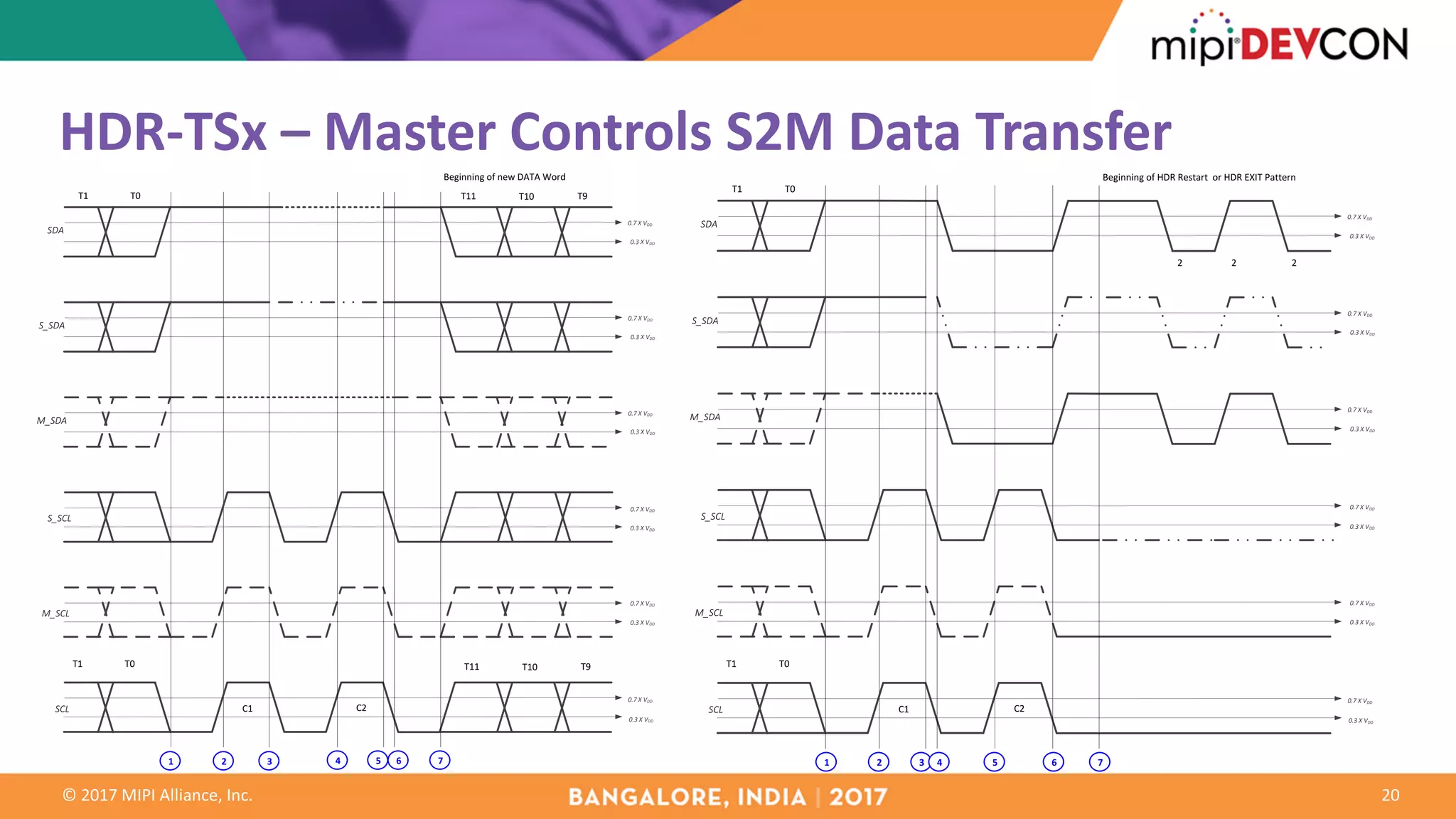
![© 2017 MIPI Alliance, Inc.
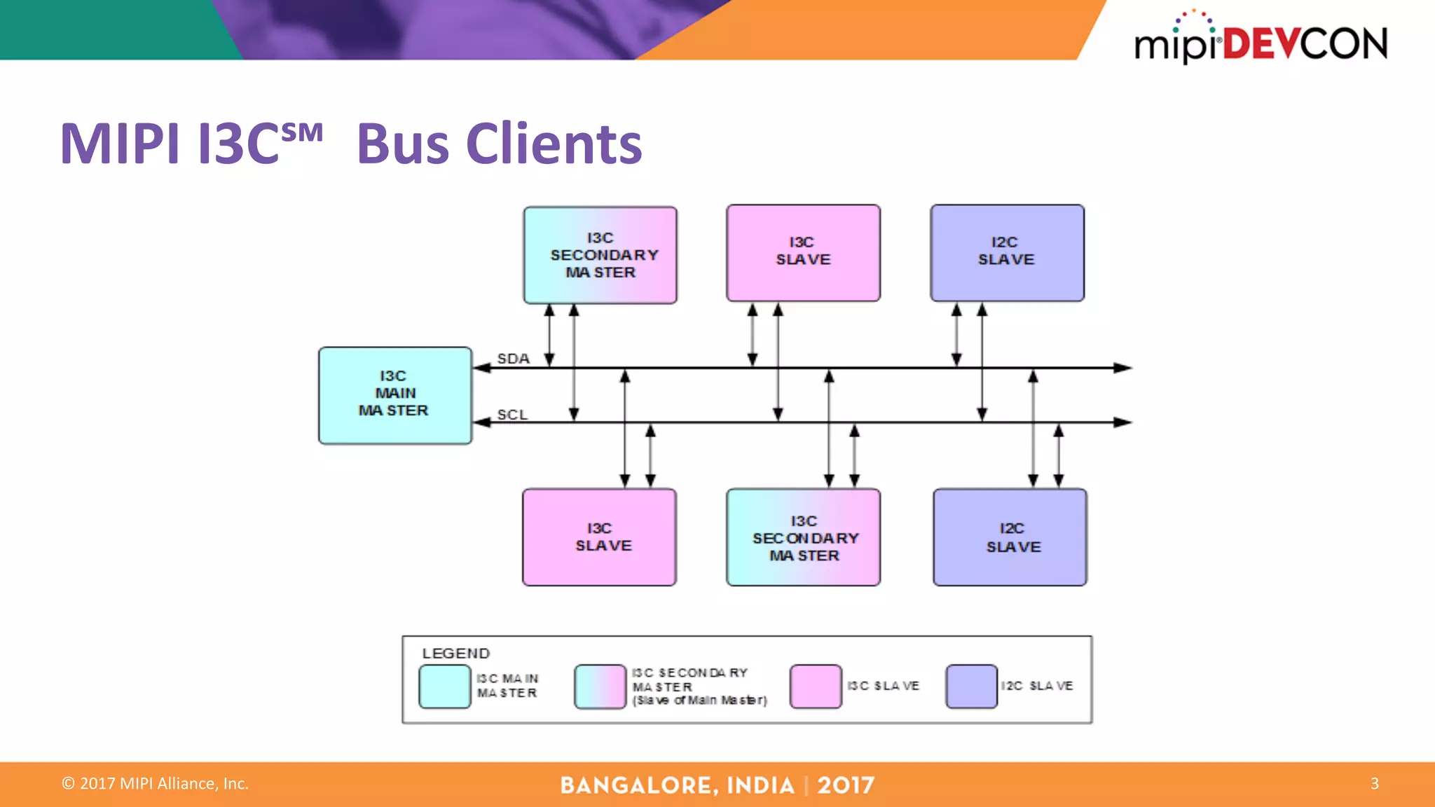
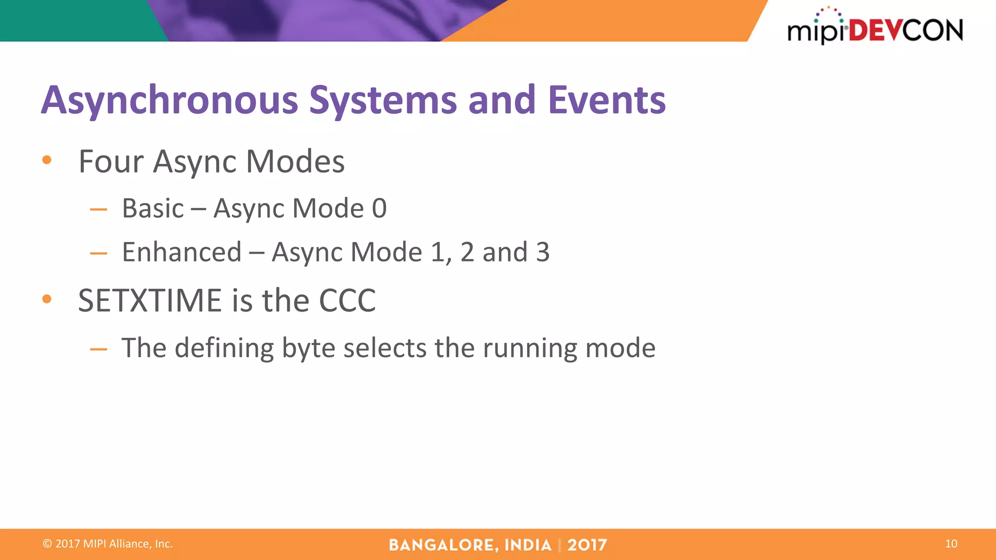
HDR-DDR – Slave controls DDR READ command
15
SCL
M_SCL
S_SCL
M_SDA
S_SDA
SDA
Beginning of new DATA Word
0.3 X VDD
0.7 X VDD
0.7 X VDD
0.7 X VDD
0.7 X VDD
0.3 X VDD
0.3 X VDD
0.3 X VDD
0.7 X VDD
0.3 X VDD
0.7 X VDD
0.3 X VDD
C1
CCC
DATA
[15:0]
C10
PAR1
CCC DATA
[15:0]
tSCO
C2
1 2 4
3
5
6
PAR0PAR1 PRE1 PRE0 D0.7 D0.6
PAR0 PRE1 PRE0 D0.7 D0.6
SCL
M_SCL
S_SCL
M_SDA
S_SDA
SDA
2 2 2
Beginning of HDR Restart or HDR EXIT Pattern
0.3 X VDD
0.7 X VDD
0.7 X VDD
0.7 X VDD
0.7 X VDD
0.3 X VDD
0.3 X VDD
0.3 X VDD
0.7 X VDD
0.3 X VDD
0.7 X VDD
0.3 X VDD
C1C10
tSCO
PAR0PAR1
CCC DATA
[15:0] PRE1 PRE0
PAR0PAR1
CCC DATA
[15:0]
PRE1 PRE0
1 2 4
3
5](https://image.slidesharecdn.com/bangalore-qualcomm-mipi-i3c-interface-advanced-features-171110191351/75/MIPI-DevCon-Bangalore-2017-MIPI-I3C-Interface-Advanced-Features-15-2048.jpg)
![© 2017 MIPI Alliance, Inc.
SCL
M_SCL
S_SCL
M_SDA
S_SDA
SDA
PAR0PAR1
2 2 2
Beginning of HDR Restart or HDR EXIT Pattern
0.3 X VDD
0.7 X VDD
0.7 X VDD
0.7 X VDD
0.7 X VDD
0.3 X VDD
0.3 X VDD
0.3 X VDD
0.7 X VDD
0.3 X VDD
0.7 X VDD
0.3 X VDD
C1
1 2 3 4 5 6 7
DATA [15:0] PRE1 PRE0
C10
PAR0PAR1DATA [15:0] PRE1 PRE0
tSCO
HDR-DDR – Master Controls DDR READ Transaction [1]
Early ending
with no CRC
16
SCL
M_SCL
S_SCL
M_SDA
S_SDA
SDA
PAR0PAR1
0.3 X VDD
0.7 X VDD
0.7 X VDD
0.7 X VDD
0.7 X VDD
0.3 X VDD
0.3 X VDD
0.3 X VDD
0.7 X VDD
0.3 X VDD
0.7 X VDD
0.3 X VDD
C1
1 2 3 4 5 6 7
DATA [15:0] PRE1 PRE0
C10
PAR0PAR1DATA [15:0] PRE1
tSCO
C2
D0.7 D0.6
PRE0 D0.7 D0.6
Beginning of new DATA Word](https://image.slidesharecdn.com/bangalore-qualcomm-mipi-i3c-interface-advanced-features-171110191351/75/MIPI-DevCon-Bangalore-2017-MIPI-I3C-Interface-Advanced-Features-16-2048.jpg)
![© 2017 MIPI Alliance, Inc.
SCL
M_SCL
S_SCL
M_SDA
S_SDA
SDA
PAR0PAR1
0.3 X VDD
0.7 X VDD
0.7 X VDD
0.7 X VDD
0.7 X VDD
0.3 X VDD
0.3 X VDD
0.3 X VDD
0.7 X VDD
0.3 X VDD
0.7 X VDD
0.3 X VDD
C1
1 2 3 4 5 6 7
DATA [15:0] PRE1 PRE0
C10
PAR0PAR1DATA [15:0] PRE1 PRE0
tSCO
Beginning of CRC
7
8 9 10 11 12
1'b1 1'b1 1'b0 1'b0
CLK_CRC1
13 14 15
CLK_CRC2 CLK_CRC3
HDR-DDR – Master Controls DDR READ Transaction [2]
Early ending
with CRC
17
SCL
M_SCL
S_SCL
M_SDA
S_SDA
SDA
PAR0PAR1
0.3 X VDD
0.7 X VDD
0.7 X VDD
0.7 X VDD
0.7 X VDD
0.3 X VDD
0.3 X VDD
0.3 X VDD
0.7 X VDD
0.3 X VDD
0.7 X VDD
0.3 X VDD
C1
1 2 3 4 5 6 7
DATA [15:0] PRE1 PRE0
C10
PAR0PAR1DATA [15:0] PRE1
tSCO
C2
D0.7 D0.6
PRE0 D0.7 D0.6
Beginning of new DATA Word](https://image.slidesharecdn.com/bangalore-qualcomm-mipi-i3c-interface-advanced-features-171110191351/75/MIPI-DevCon-Bangalore-2017-MIPI-I3C-Interface-Advanced-Features-17-2048.jpg)
![© 2017 MIPI Alliance, Inc.
HDR-DDR – Slave Requests DDR WRITE Termination [1]
18
SCL
M_SCL
S_SCL
M_SDA
S_SDA
SDA
PAR0PAR1
Beginning of new DATA Word
0.3 X VDD
0.7 X VDD
0.7 X VDD
0.7 X VDD
0.7 X VDD
0.3 X VDD
0.3 X VDD
0.3 X VDD
0.7 X VDD
0.3 X VDD
0.7 X VDD
0.3 X VDD
C1
1 2 3 4 5 6 7
DATA [15:0] PRE1 PRE0
C10
PAR0PAR1DATA [15:0] PRE1 PRE0
tSCO
C2
D0.7 D0.6
D0.7 D0.6
SCL
M_SCL
S_SCL
M_SDA
S_SDA
SDA
PAR0PAR1
2 2 2
Beginning of HDR Restart or HDR EXIT Pattern
0.3 X VDD
0.7 X VDD
0.7 X VDD
0.7 X VDD
0.7 X VDD
0.3 X VDD
0.3 X VDD
0.3 X VDD
0.7 X VDD
0.3 X VDD
0.7 X VDD
0.3 X VDD
C1
1 2 3 4 5 6 7
DATA [15:0] PRE1 PRE0
C10
PAR0PAR1DATA [15:0] PRE1 PRE0
tSCO
Early ending
with no CRC](https://image.slidesharecdn.com/bangalore-qualcomm-mipi-i3c-interface-advanced-features-171110191351/75/MIPI-DevCon-Bangalore-2017-MIPI-I3C-Interface-Advanced-Features-18-2048.jpg)
![© 2017 MIPI Alliance, Inc.
HDR-DDR – Slave Requests DDR WRITE Termination [2]
19
SCL
M_SCL
S_SCL
M_SDA
S_SDA
SDA
PAR0PAR1
Beginning of new DATA Word
0.3 X VDD
0.7 X VDD
0.7 X VDD
0.7 X VDD
0.7 X VDD
0.3 X VDD
0.3 X VDD
0.3 X VDD
0.7 X VDD
0.3 X VDD
0.7 X VDD
0.3 X VDD
C1
1 2 3 4 5 6 7
DATA [15:0] PRE1 PRE0
C10
PAR0PAR1DATA [15:0] PRE1 PRE0
tSCO
C2
D0.7 D0.6
D0.7 D0.6
Early ending
with CRC
M_SDA
S_SDA
SCL
M_SCL
S_SCL
SDA
PAR0PAR1
0.3 X VDD
0.7 X VDD
0.7 X VDD
0.7 X VDD
0.7 X VDD
0.3 X VDD
0.3 X VDD
0.3 X VDD
0.7 X VDD
0.3 X VDD
0.7 X VDD
0.3 X VDD
C1
1 2 3 4 5 6 7
DATA [15:0] PRE1 PRE0
C10
PAR0PAR1DATA [15:0] PRE1 PRE0
tSCO
Beginning of CRC
1'b1 1'b1 1'b0 1'b0
CLK_CRC1
8 9 10 11
6
7
12
CLK_CRC2 CLK_CRC3](https://image.slidesharecdn.com/bangalore-qualcomm-mipi-i3c-interface-advanced-features-171110191351/75/MIPI-DevCon-Bangalore-2017-MIPI-I3C-Interface-Advanced-Features-19-2048.jpg)


The document discusses the MIPI I3C interface, detailing its advanced features such as intelligent multi-featured communication, dynamic address assignment, and timing control for synchronous and asynchronous systems. It highlights the bus's capabilities to support multiple message types and flow control mechanisms while addressing problems and practical implementation challenges. Additionally, it examines the interaction of various components within the I3C framework, including command codes and transaction control methods.