Download as PDF, PPTX

![Co-Design
int UniProMemoryXactor_sc::WriteTransaction(u_int8_t *pBuf,
u_int16_t wBytesCount,
bool IsBlocking)
{
…
UniProMemoryWrite((svBitVecVal *)pTxBuf,(int)wBytesCount, (IsBlocking)?1:0);
if (IsBlocking) {
wait(Done);
};
…
}
6
function void UniProMemoryWrite(input bit [COMODEL_BUF_SIZE-1:0] Buf,
int BytesCount,
int IsBlocking);
WrIsBlock = IsBlocking;
WrDataWordsCounts = ((BytesCount/(DATA_WIDTH/8)) + ((BytesCount%(DATA_WIDTH/8))?1:0));
WrBytesOfLastWord = BytesCount - (WrDataWordsCounts-1)*(DATA_WIDTH/8);
WrLastBe = (WrBytesOfLastWord == 8 ) ? 8'hFF:
(WrBytesOfLastWord == 7 ) ? 8'h7F:
(WrBytesOfLastWord == 6 ) ? 8'h3F:
(WrBytesOfLastWord == 5 ) ? 8'h1F:
(WrBytesOfLastWord == 4 ) ? 8'h0F:
(WrBytesOfLastWord == 3 ) ? 8'h07:
(WrBytesOfLastWord == 2 ) ? 8'h03:
(WrBytesOfLastWord == 1 ) ? 8'h01:
8'hFF;
for(int i =0 ; i< WrDataWordsCounts; i = i + 1 ) begin
WrBuf[i] = Buf[(DATA_WIDTH)*i +: DATA_WIDTH];
end
->e_StartWr;
endfunction;
C++ proxy
un;med so?ware model
XRTL counterpart](https://image.slidesharecdn.com/verificationofmobilesocdesign-160926032213/75/MIPI-DevCon-2016-Verification-of-Mobile-SOC-Design-UFS-6-2048.jpg)

![SW/HW Interface (DME/NL SAPs)
8
Data Symbol # Bit fields
0
[15:0] DME_SAP opcode
[31:16] GenSelectorIndex or SelectorIndex
[47:32] MIBaUribute or GenMIBaUribute
[55:48] ResultCode: used for GenericErrorCode, ConfigResultCode and PowerChangeResultCode,
DLErrorCode
[56] AUrSetType
[57] ResetLevel
[58] PAResult
[59] PHYDirec;on
1 [31:0] MIBvalue
2,3,4 PAPowerModeUserData](https://image.slidesharecdn.com/verificationofmobilesocdesign-160926032213/75/MIPI-DevCon-2016-Verification-of-Mobile-SOC-Design-UFS-8-2048.jpg)
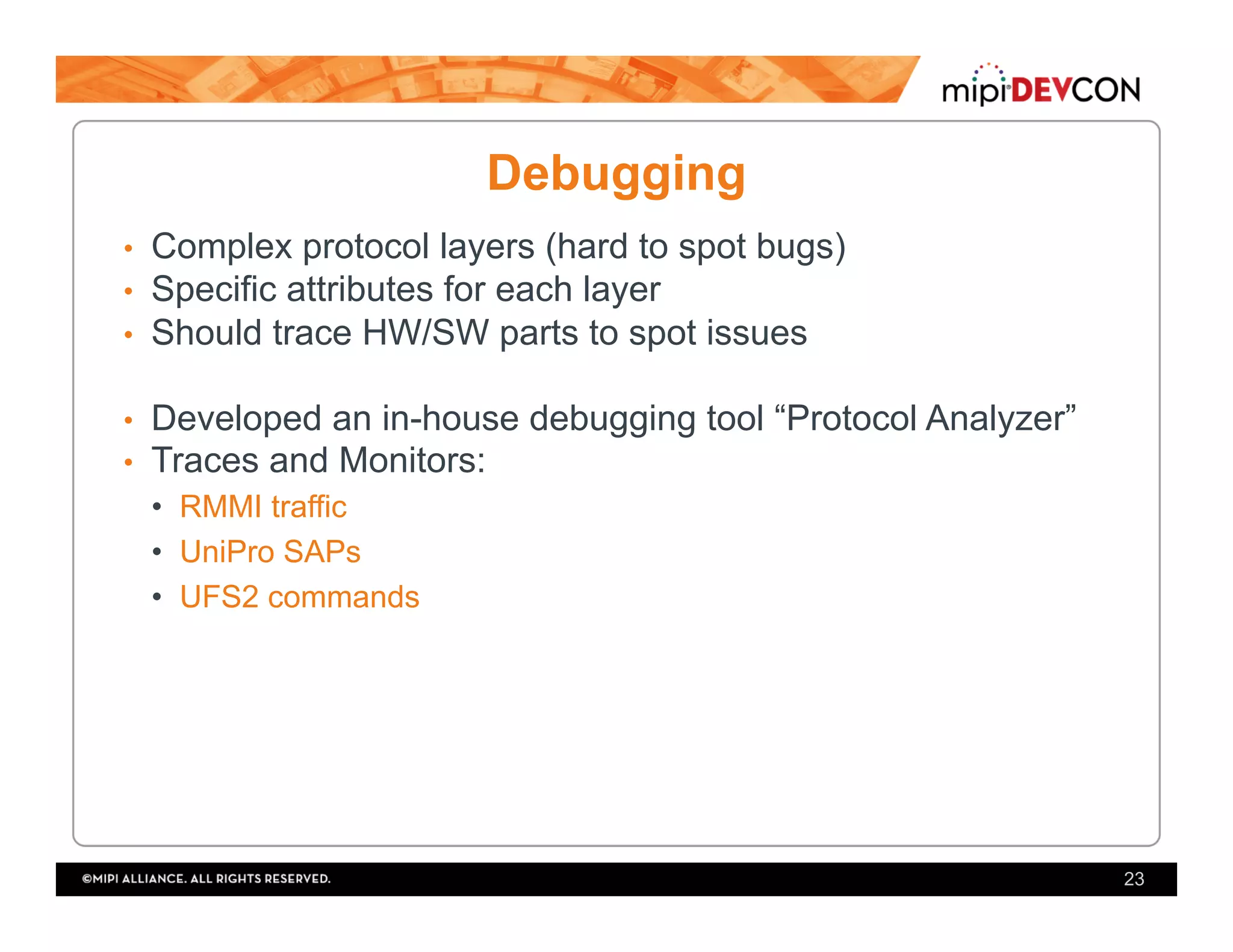
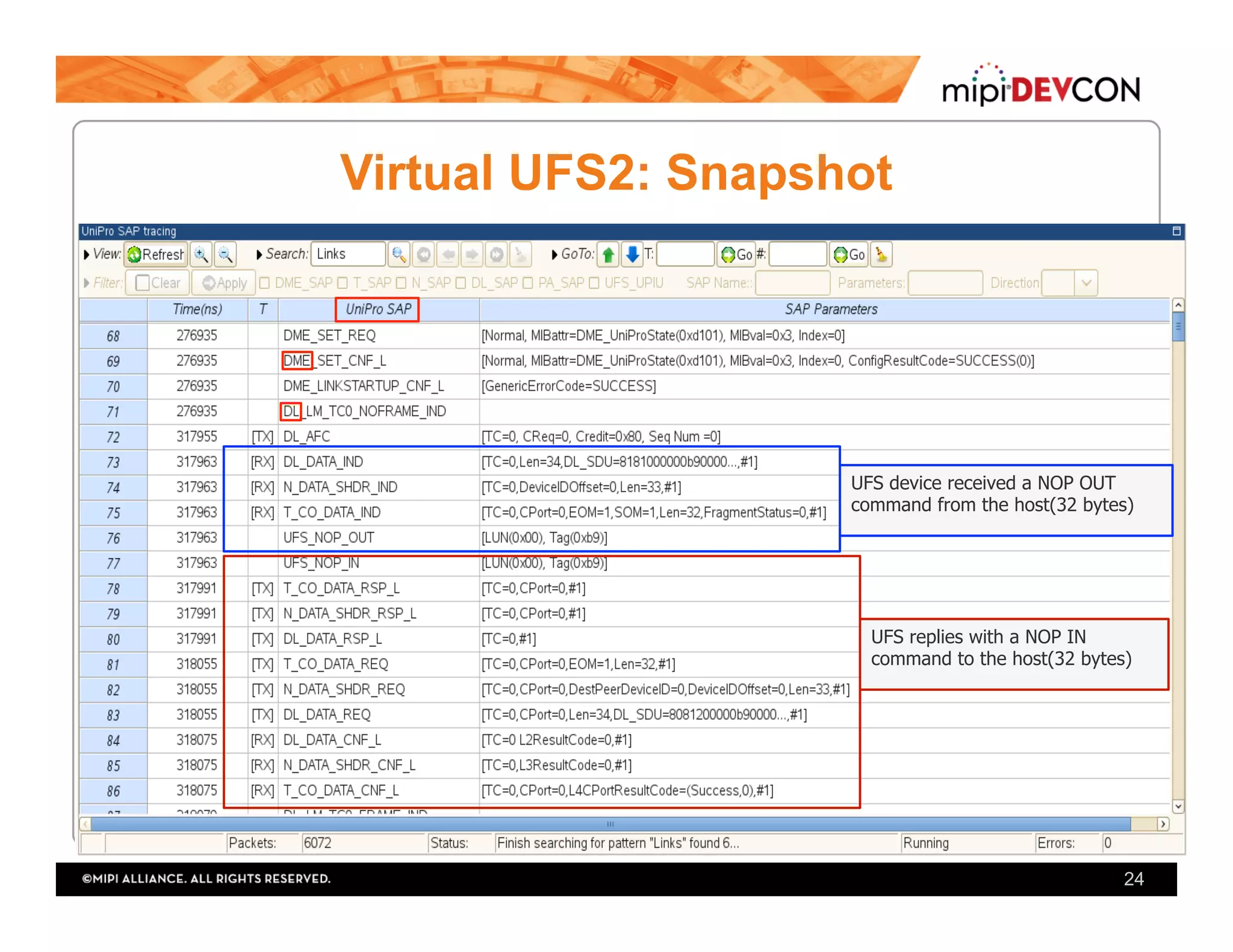
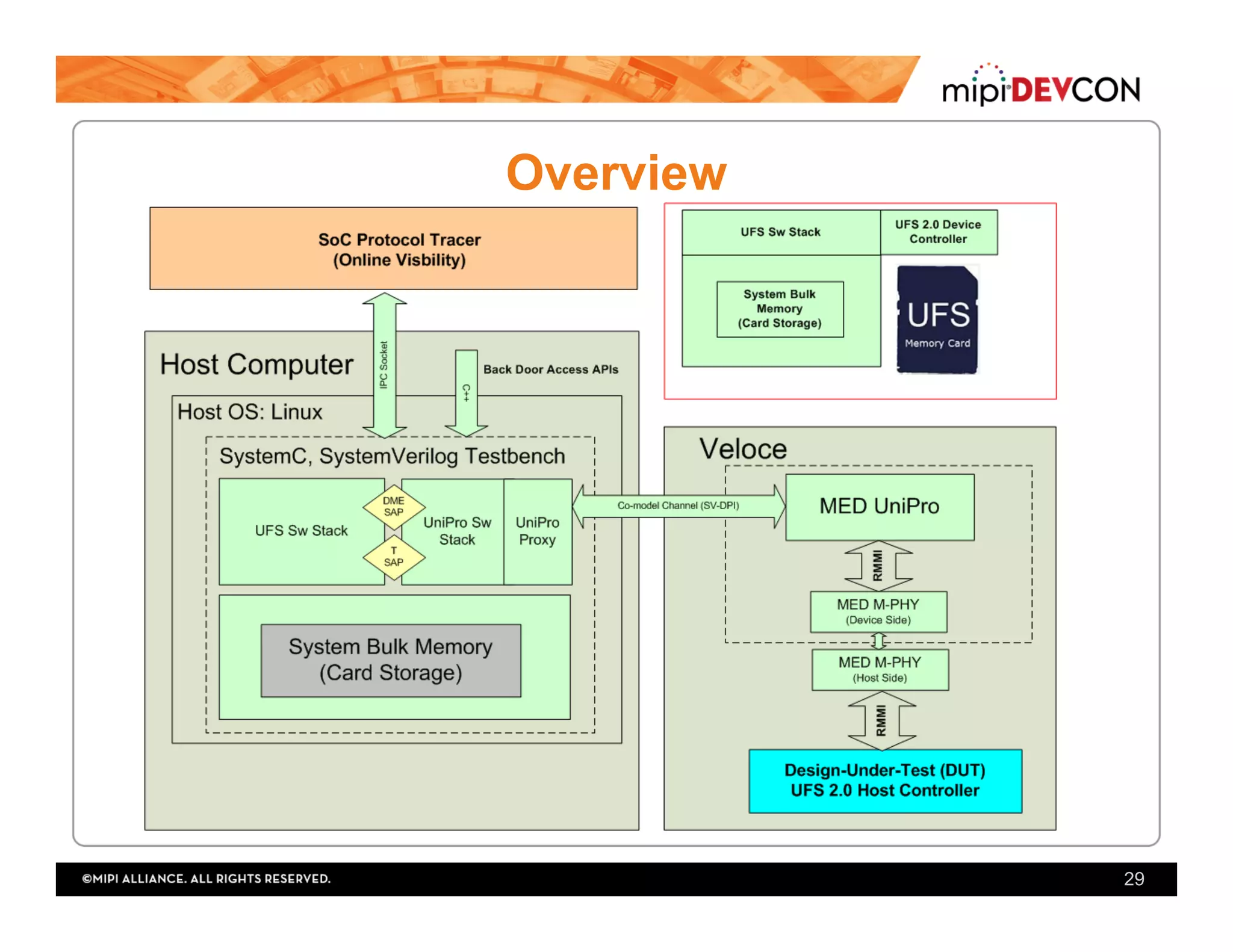
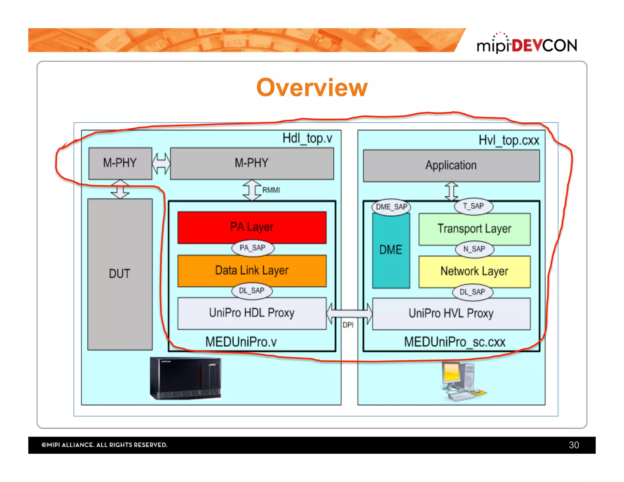
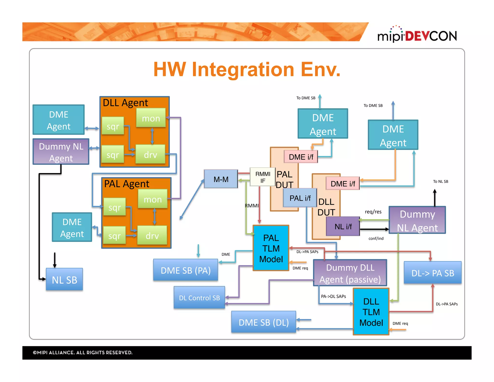
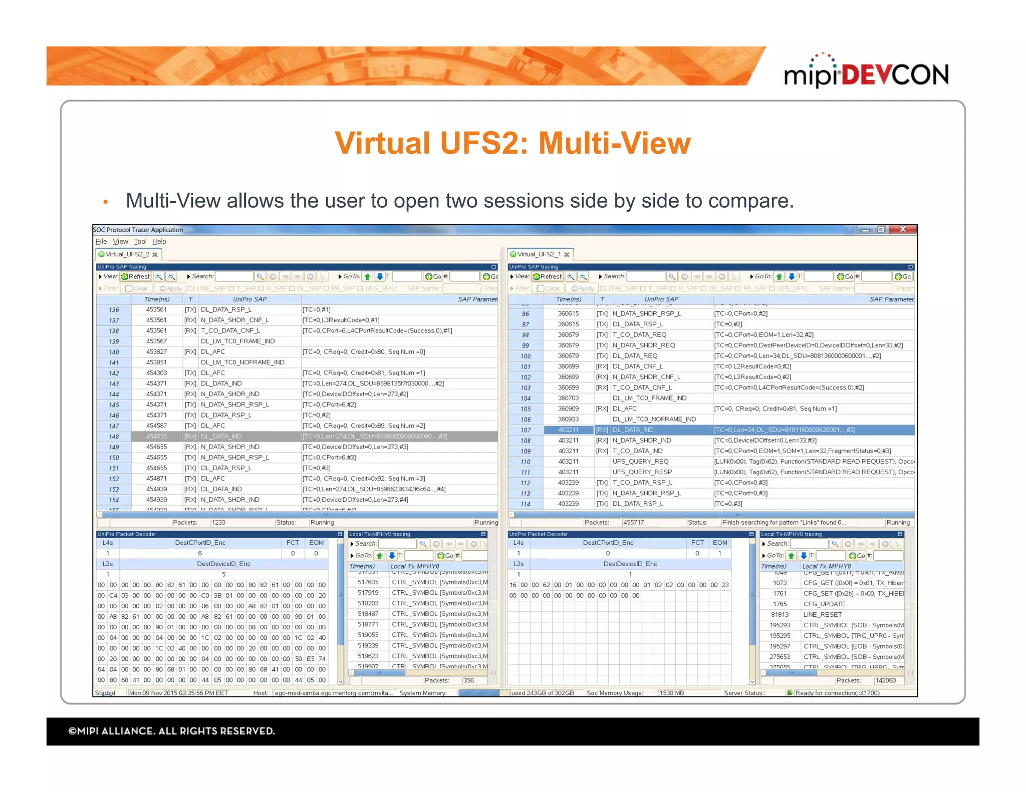
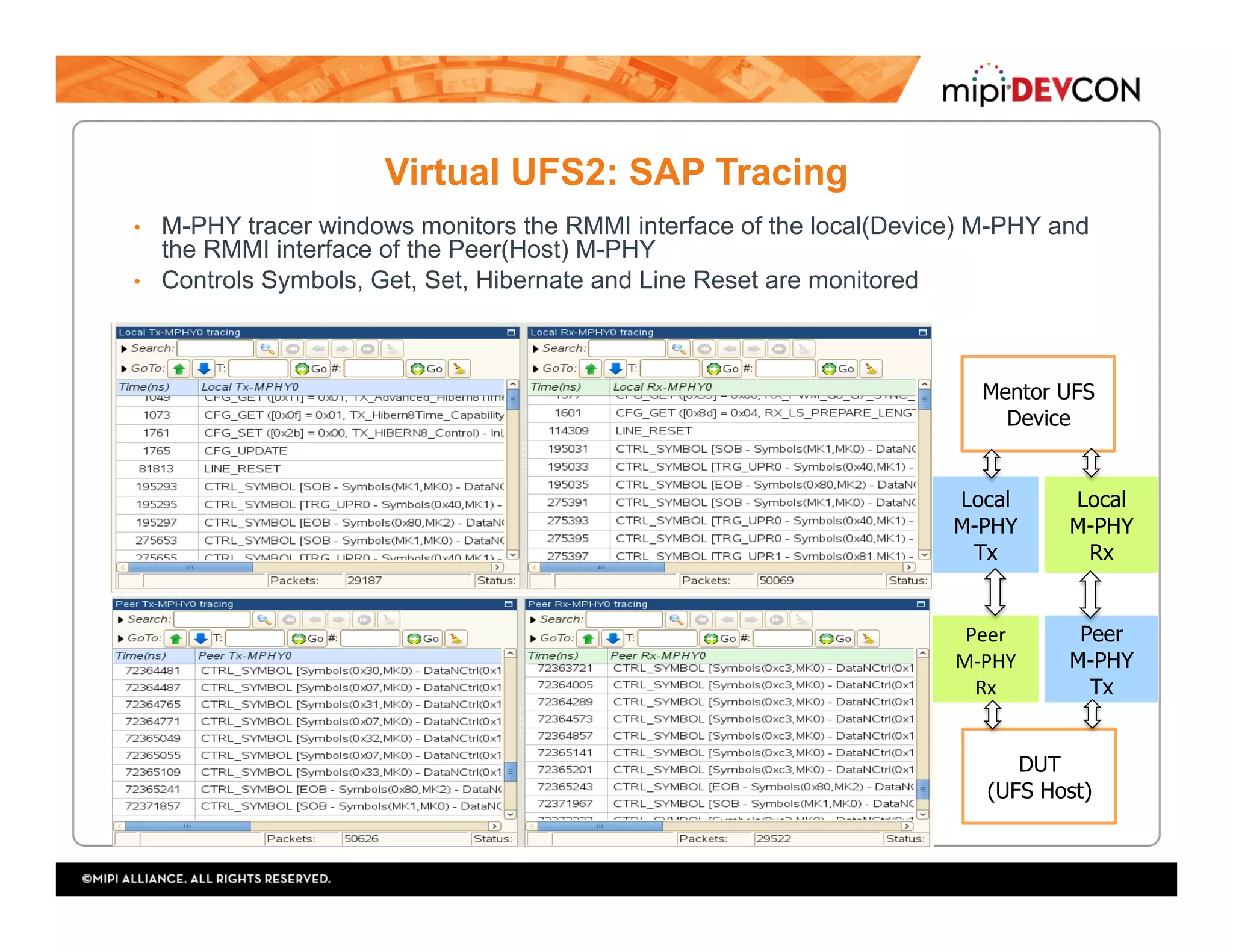

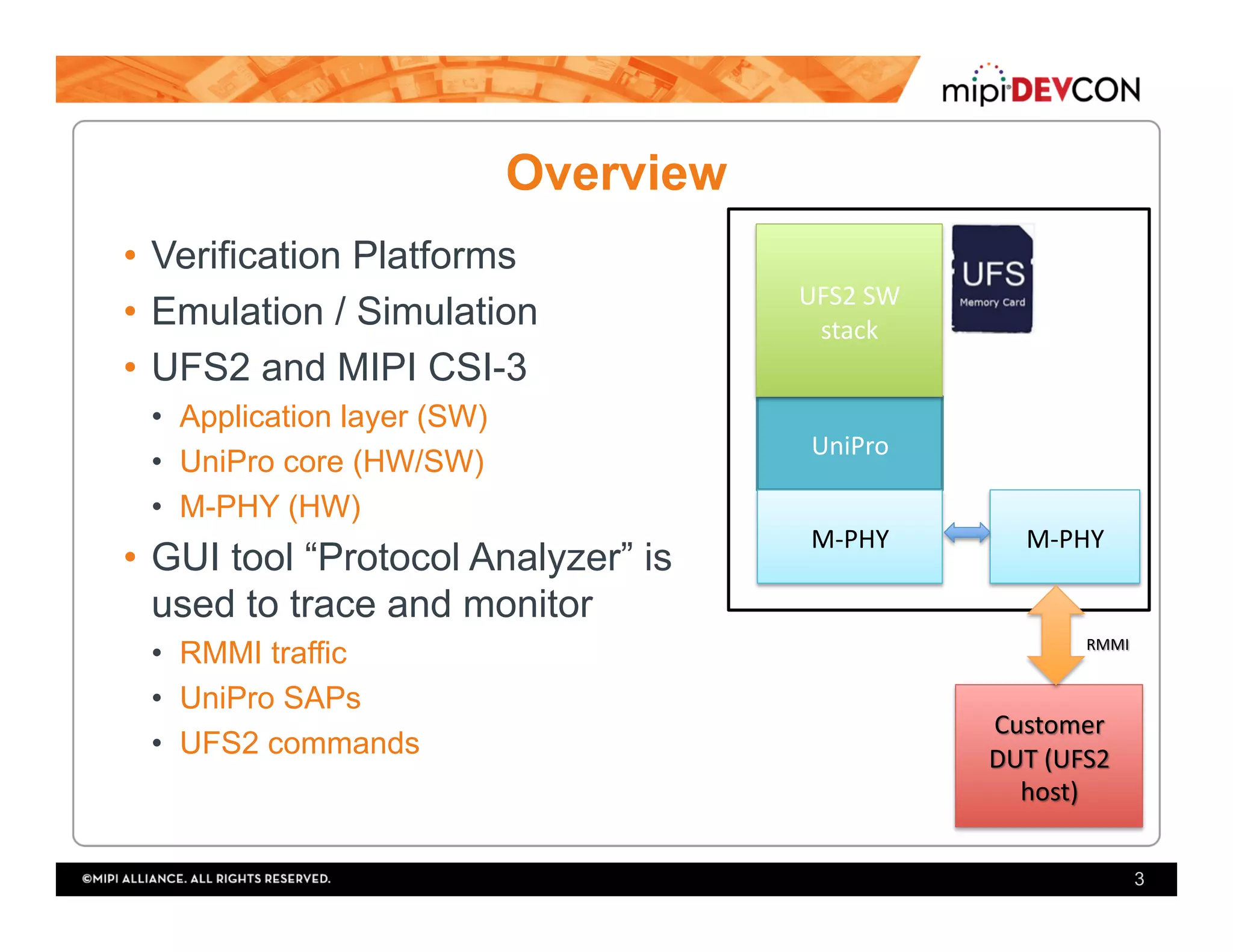
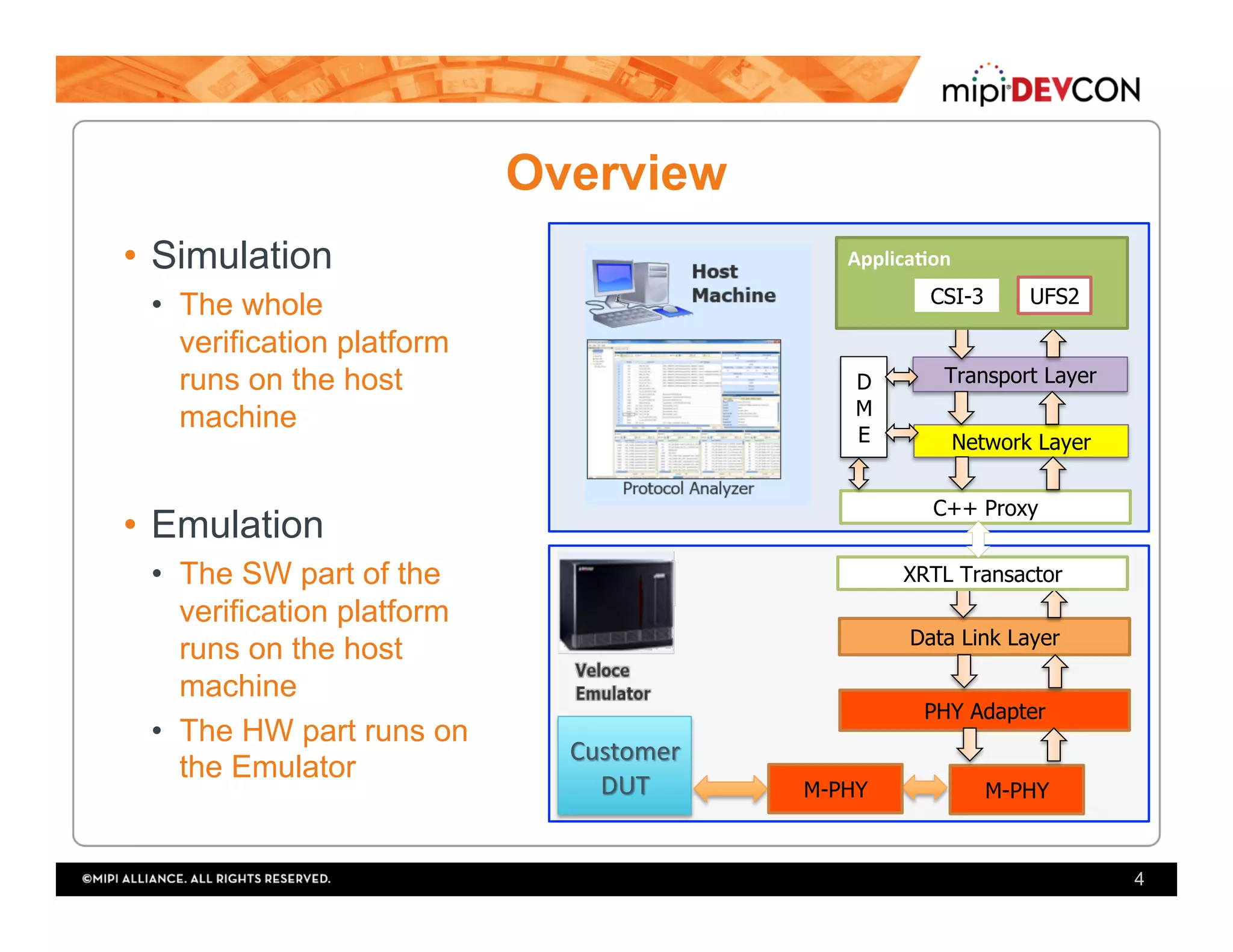
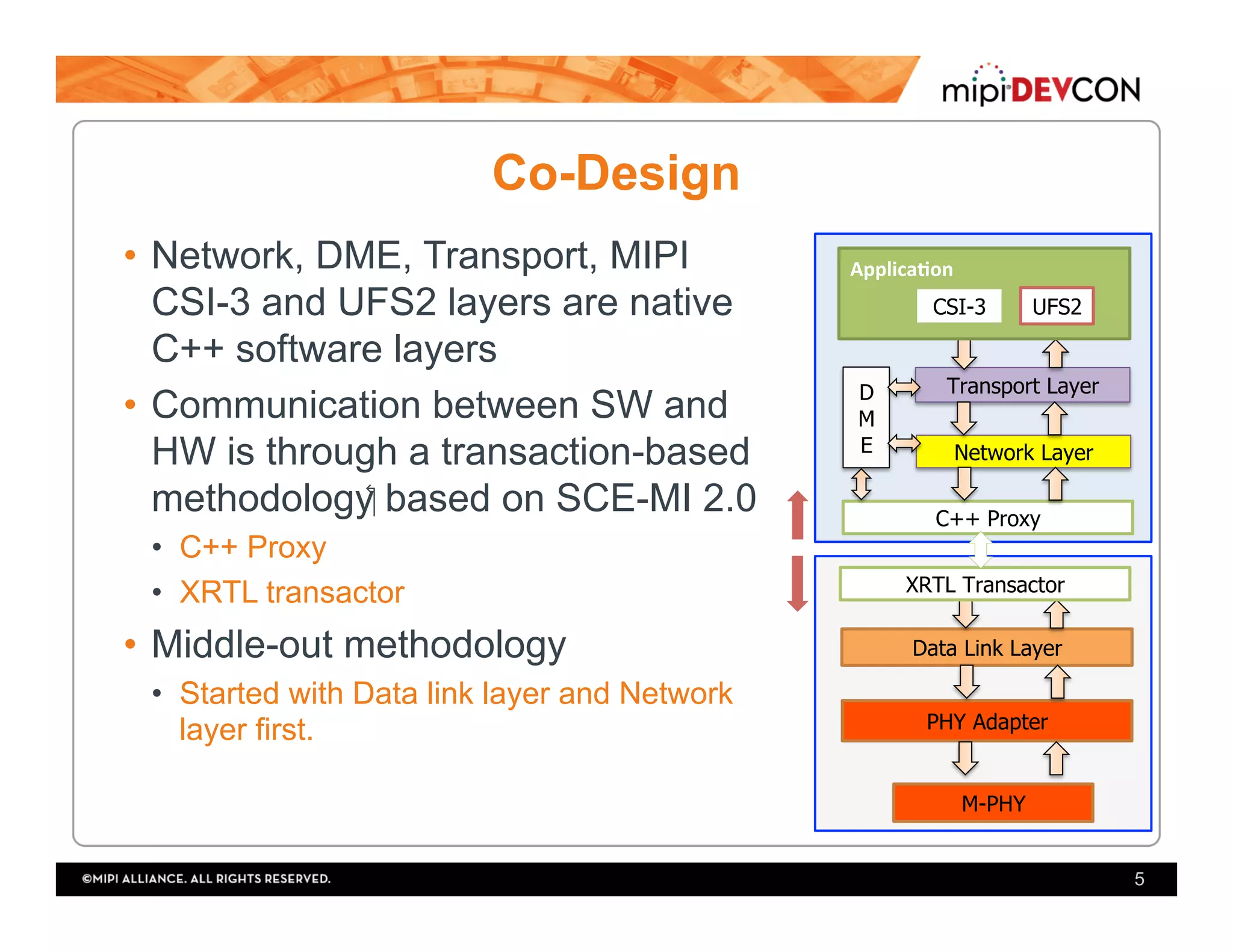
The document outlines the verification process for mobile SoC design specifically focusing on the UFS protocol and its integration with hardware and software components. It emphasizes the use of various verification platforms, design considerations, and debugging tools like a protocol analyzer to trace and monitor traffic. Additionally, it discusses system level testing and the challenges faced during hardware integration and verification of the layers involved.