Download as PDF, PPTX
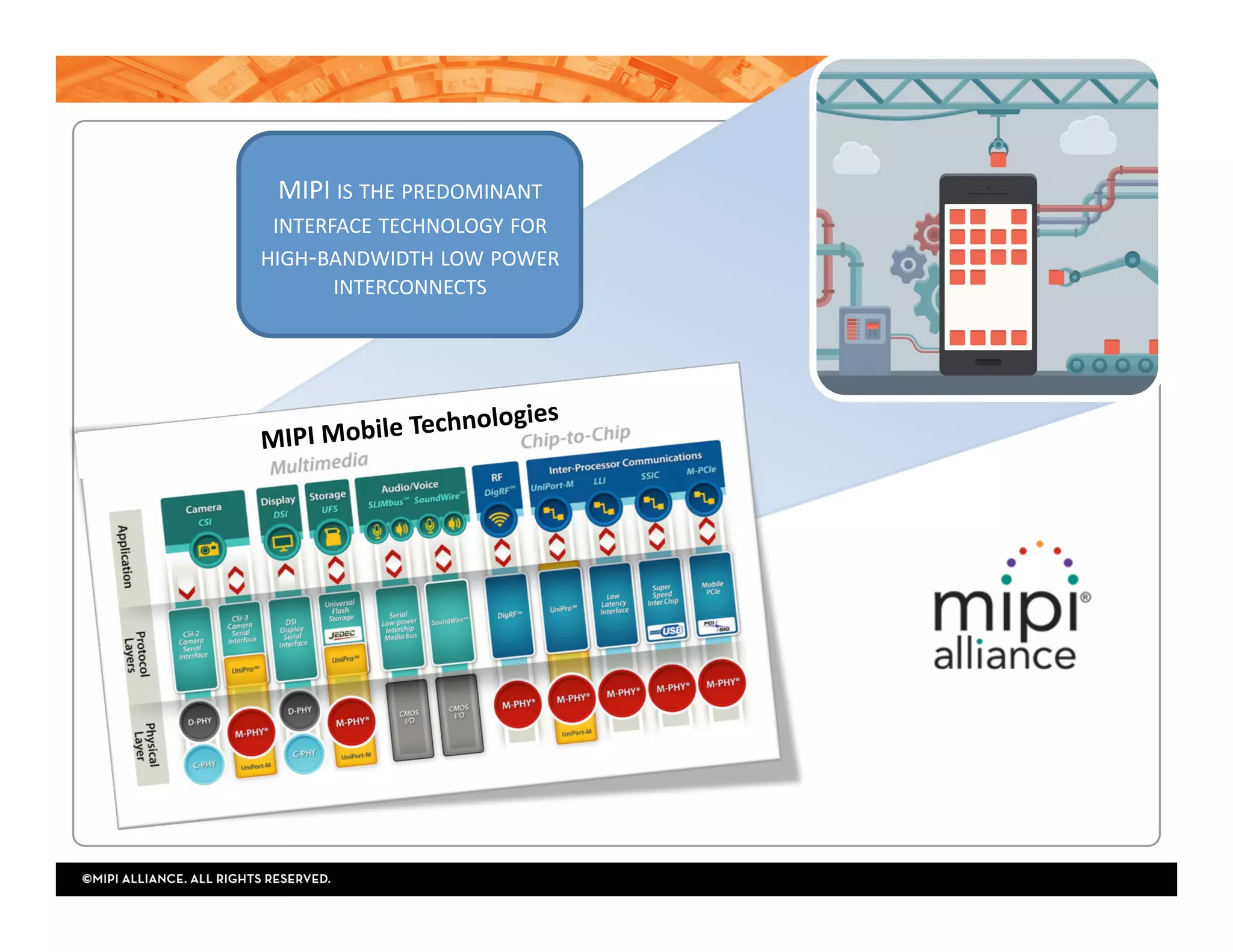

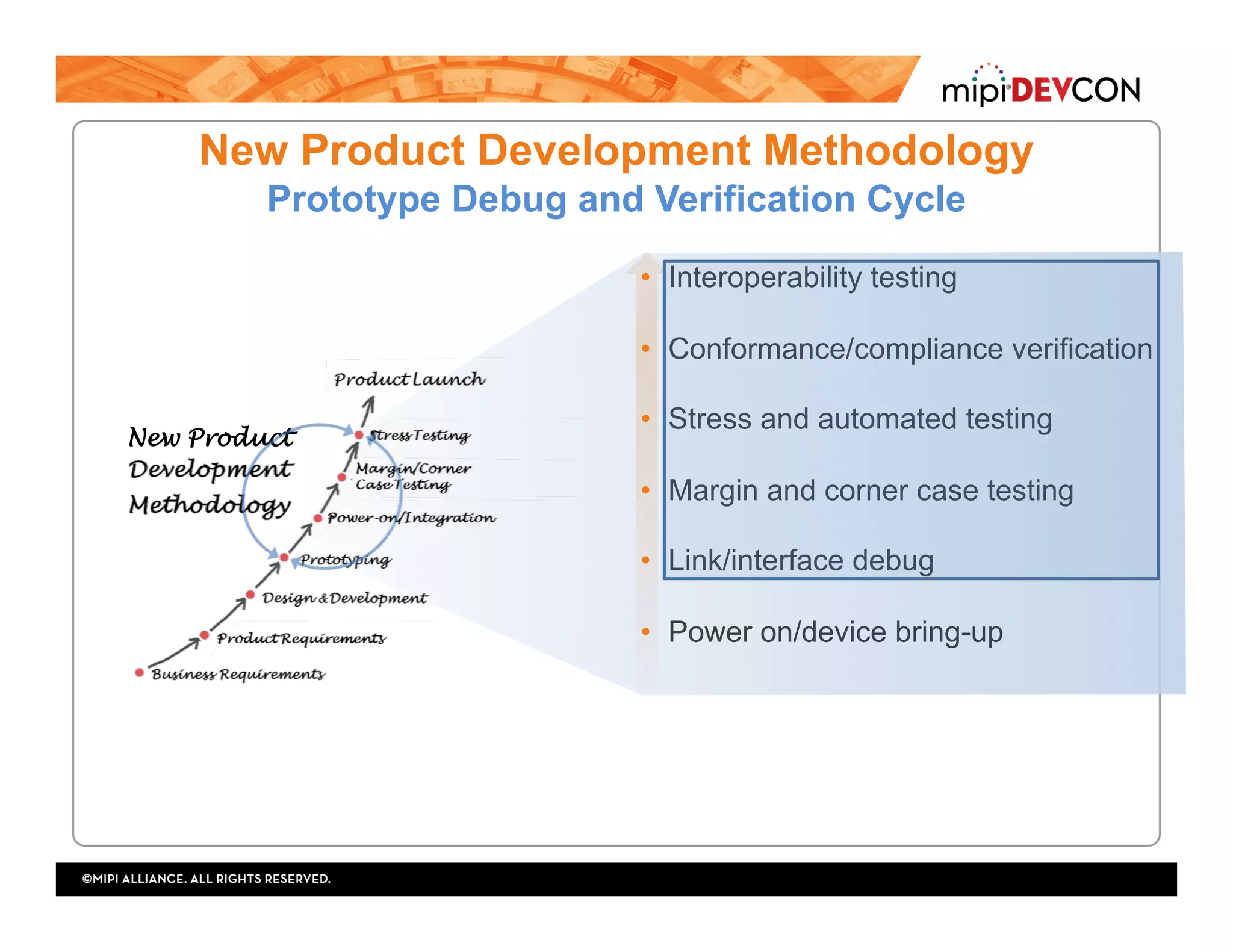
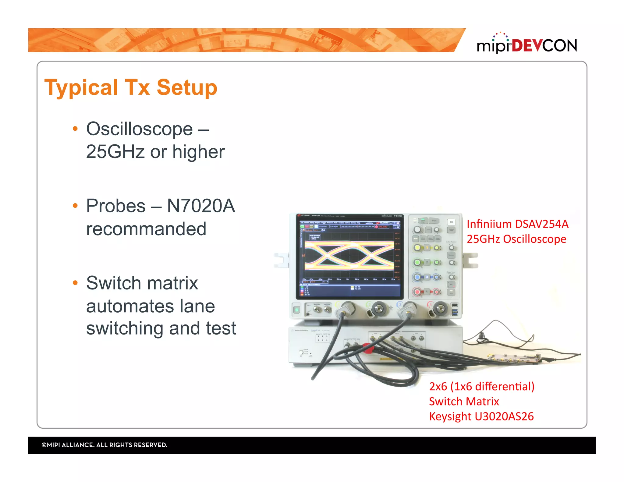
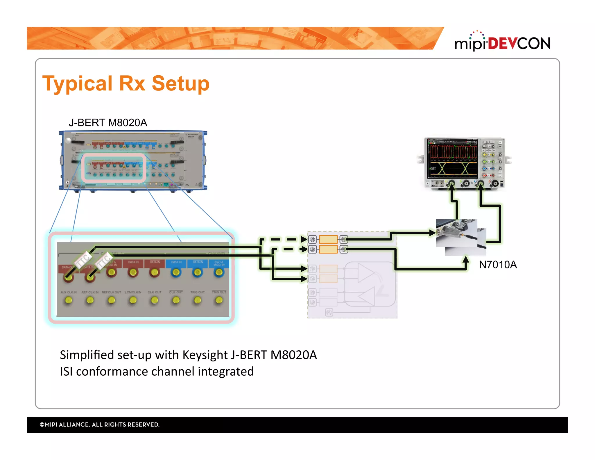
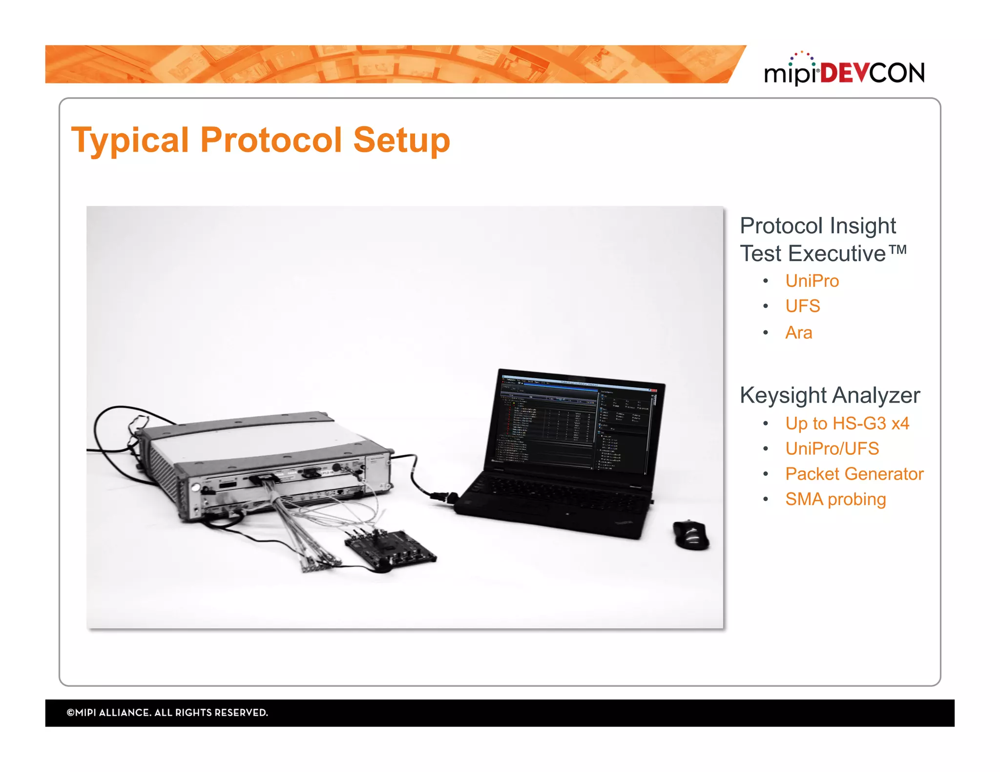
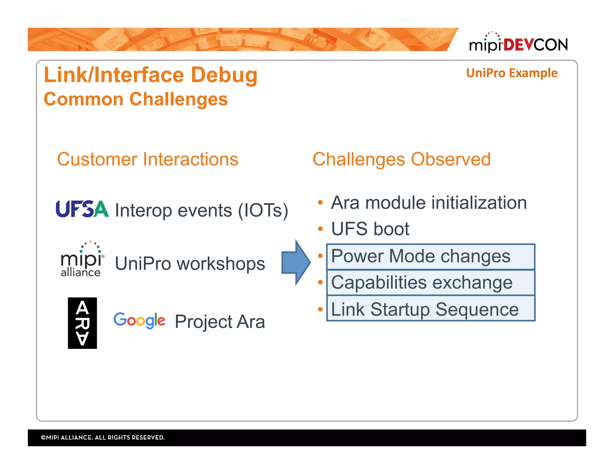
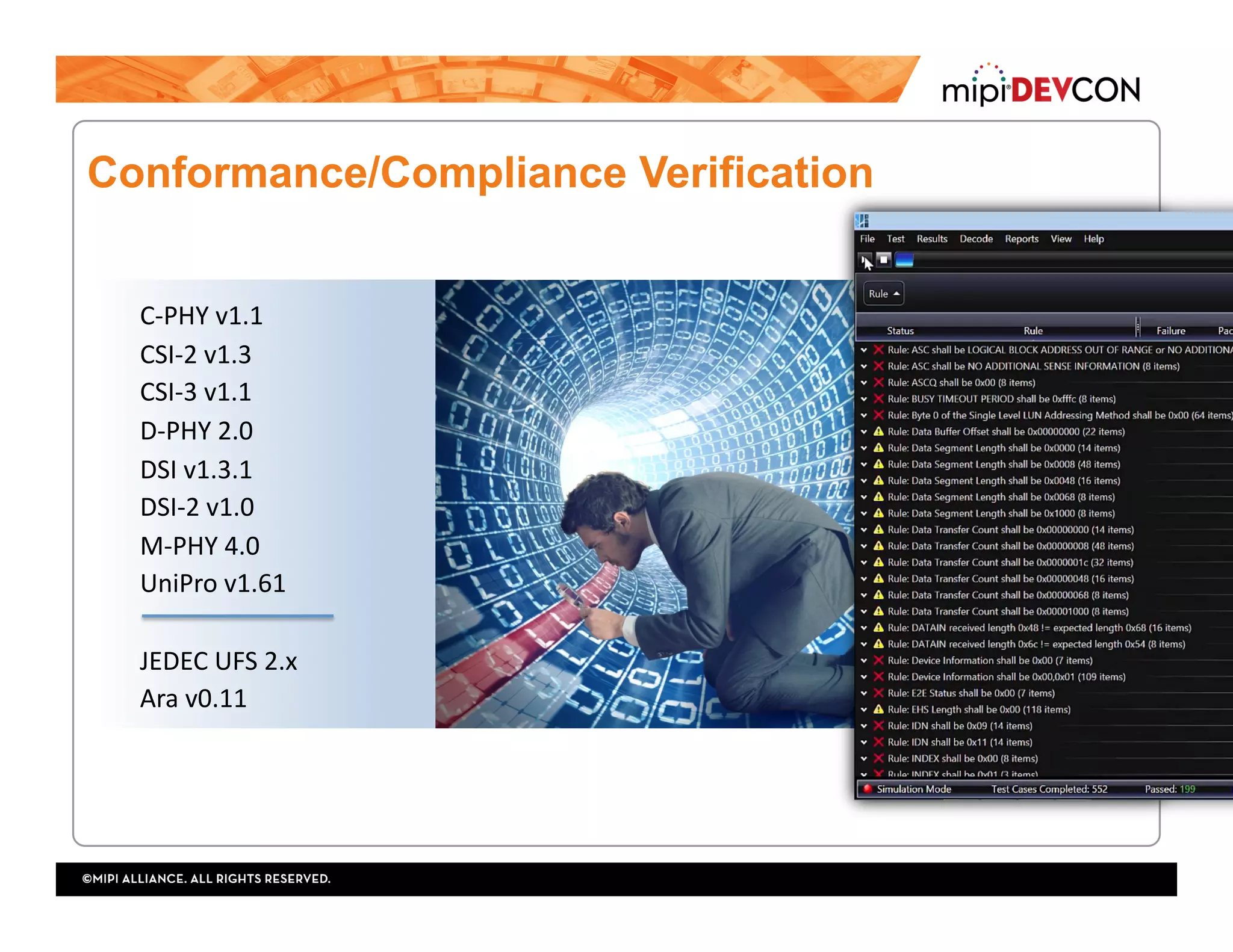
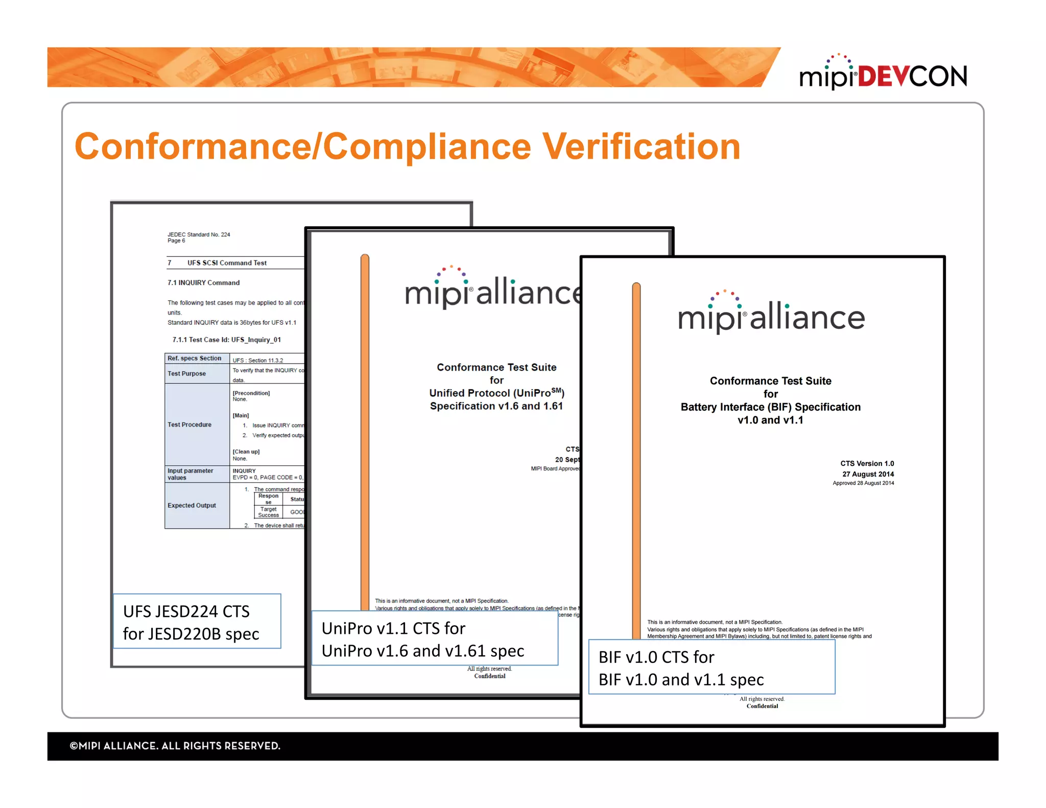
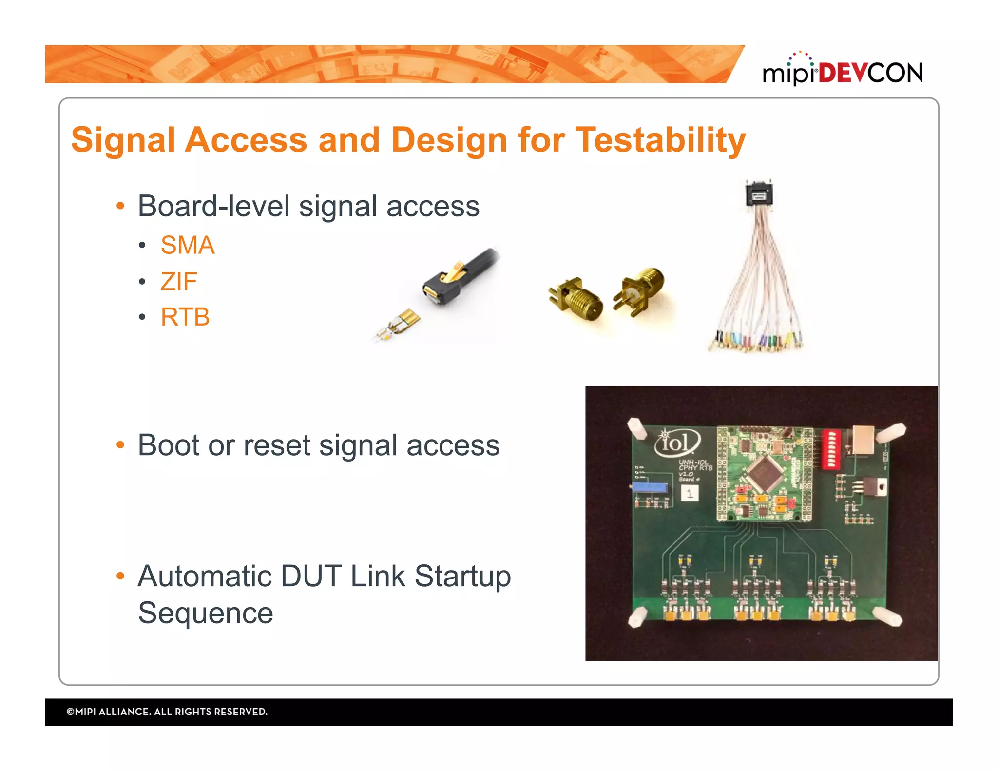
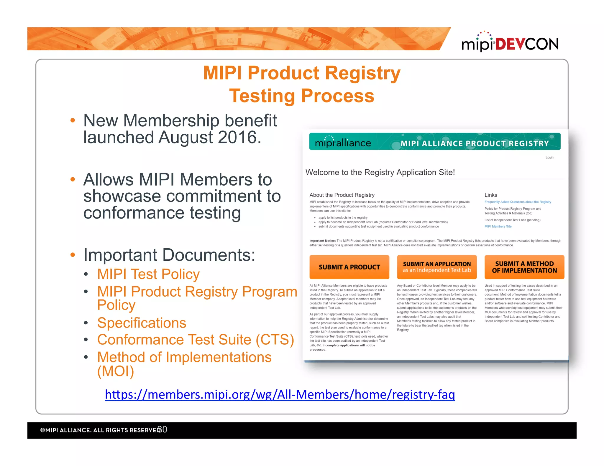
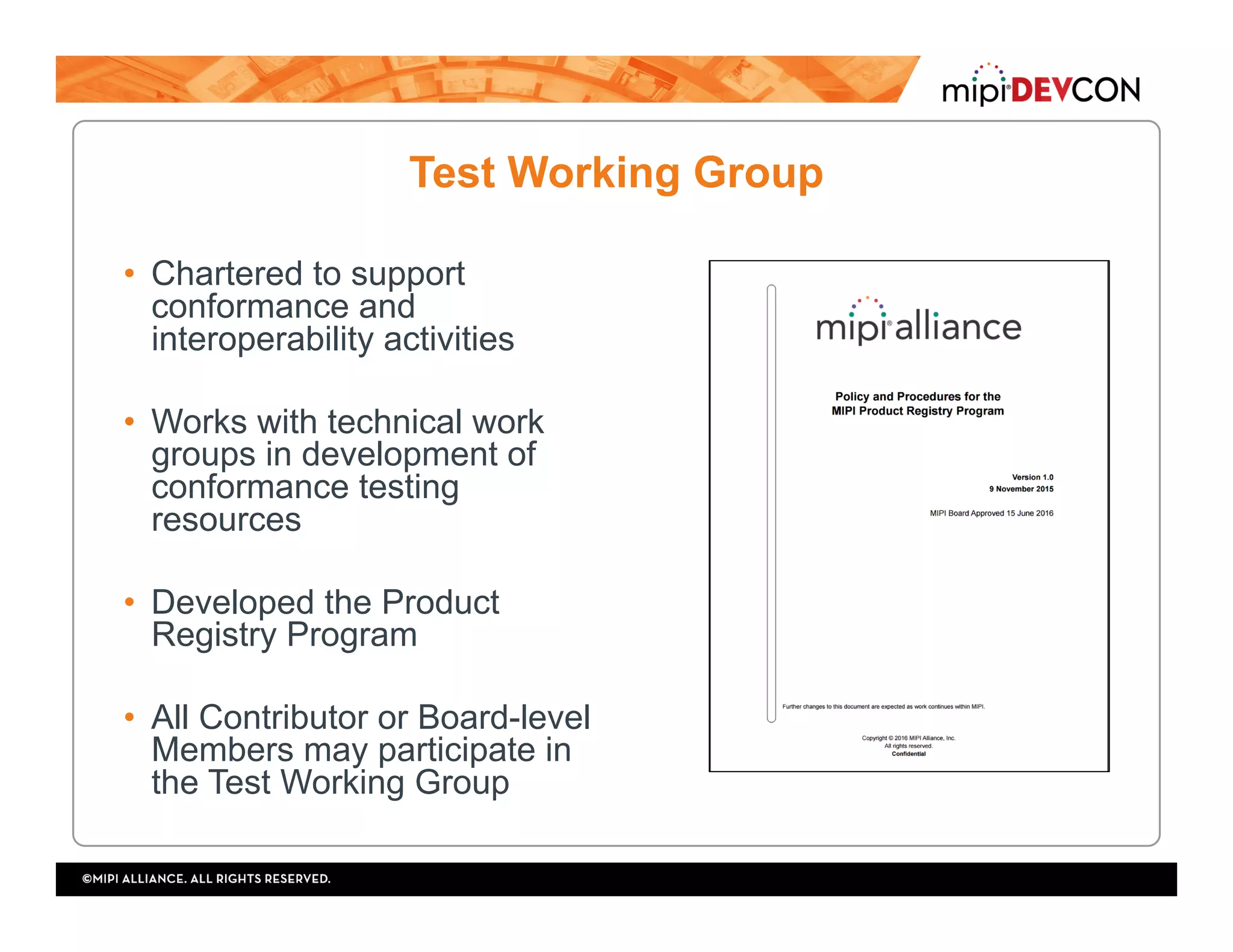
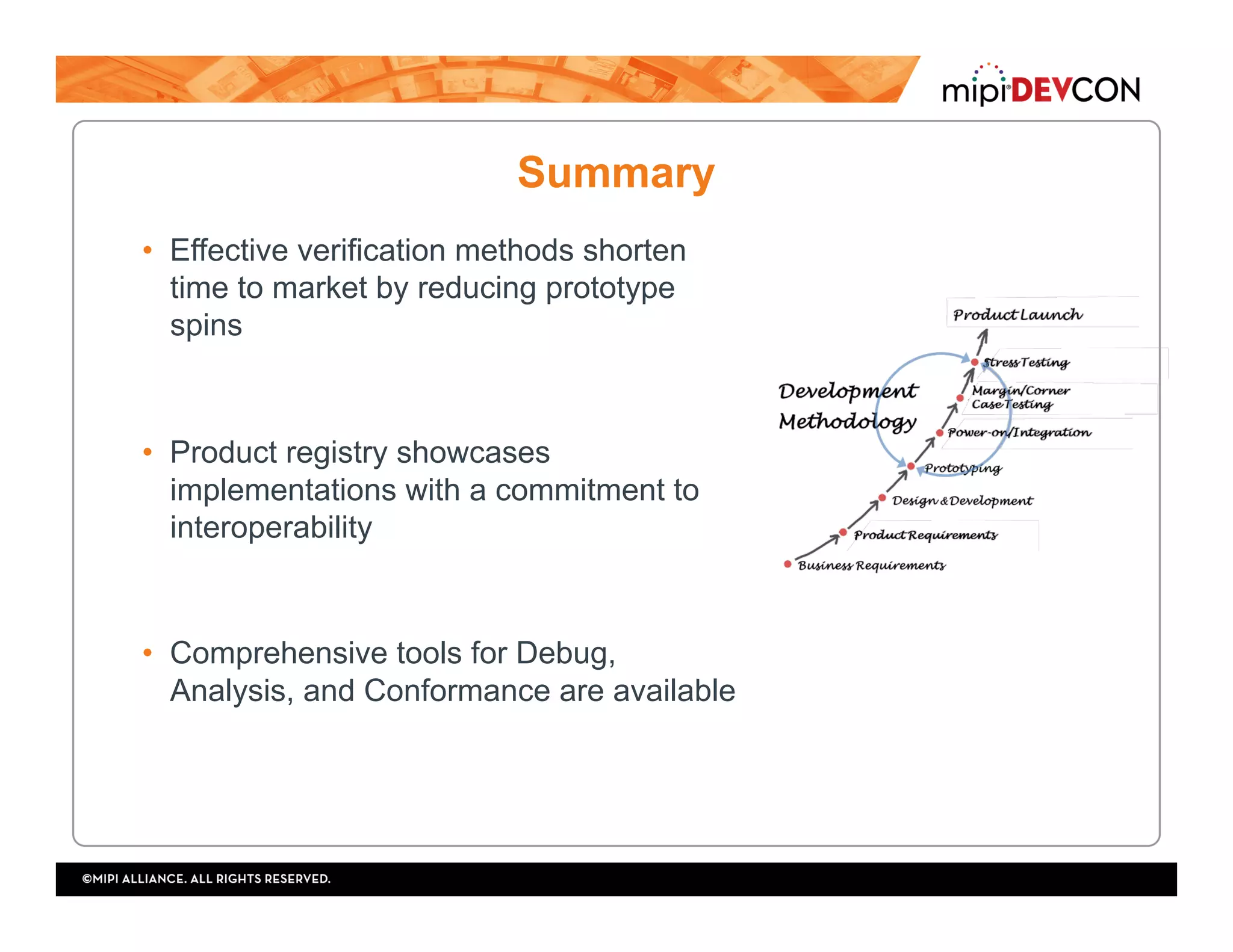


The document focuses on MIPI's methodologies for robust debug and conformance verification of mobile technologies, aimed at ensuring interoperability and reducing time to market. It outlines various testing processes, including interoperability testing, conformance verification, and stress testing, and highlights common challenges faced during these tests. Additionally, it discusses the MIPI product registry and the roles of test working groups in supporting conformance and interoperability activities.