


![Reference•http://www.slideshare.net/BhaumikBhatt4/universal-flash-storage
•http://www.jedec.org/standards-documents/focus/flash/universal-flash-storage-ufs
•http://universalflash.org/wp-content/uploads/2011/06/1306_UFSA_White_Paper.pdf
•Available on JEDEC web Site !
•JESD220B Universal Flash Storage Version 2.0
•JESD220-1 UFS Unified Memory Extension ( Device side )
•JESD223B UFS Host Controller Interface (UFSHCI) version 2.0
•JESD223-1 UFS Host Controller Interface (UFSHCI), Unified Memory Extension - Host (HCI) Side
•JESD224 UFS (Test)
[MIPI-M-PHY], MIPI Alliance Specification for M-PHYSM, Version 3.0
[MIPI-UniPro], MIPI Alliance Specification for Unified Protocol (UniProSM), Version 1.6
[MIPI-DDB], MIPI Alliance Specification for Device Descriptor Block (DDB), Version
[SAM], INCITS T10 draft standard: SCSI Architecture Model – 5 (SAM–5), Revision 05, 19 May 2010
[SPC], INCITS T10 draft standard: SCSI Primary Commands – 4 (SPC-4), Revision 27, 11 October 2010
[SBC], INCITS T10 draft standard: SCSI Block Commands – 3 (SBC–3), Revision 24, 05 August 2010
https://www.kernel.org/doc/Documentation/scsi/ufs.txt
http://en.wikipedia.org/wiki/SCSI_mode_page
http://www.tldp.org/HOWTO/archived/SCSI-Programming-HOWTO/
•http://en.wikipedia.org/wiki/SCSI_CDB
•https://vimeo.com/72052801
Understanding SCSI Sense 참고
http://blog.disksurvey.org/knowledge-base/scsi-sense/
Sensekey
http://www.t10.org/lists/2sensekey.htm
ASC/ASCQ
http://www.t10.org/lists/op-num.htm](https://image.slidesharecdn.com/universalflashstorage-150313095453-conversion-gate01/75/Universal-flash-storage-34-2048.jpg)


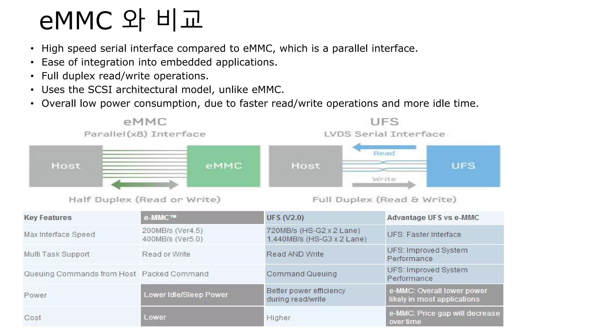
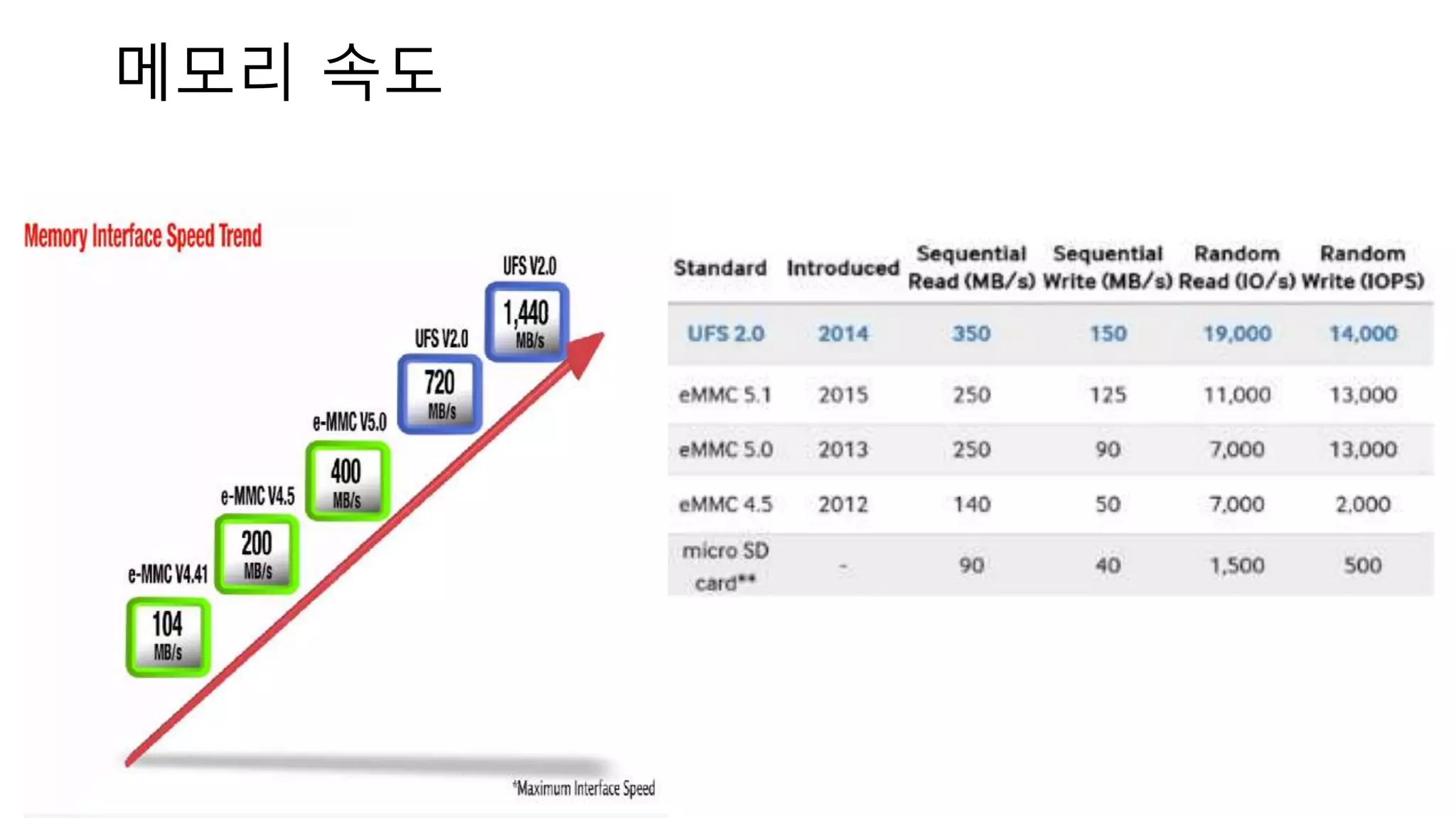
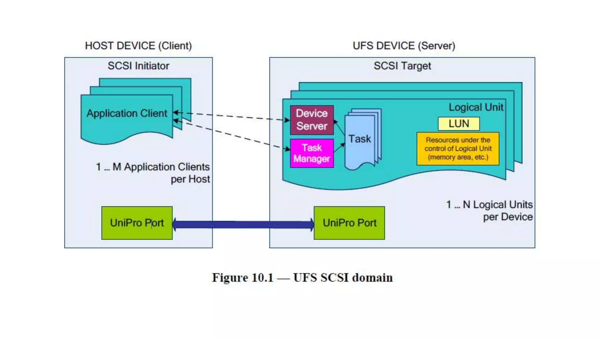
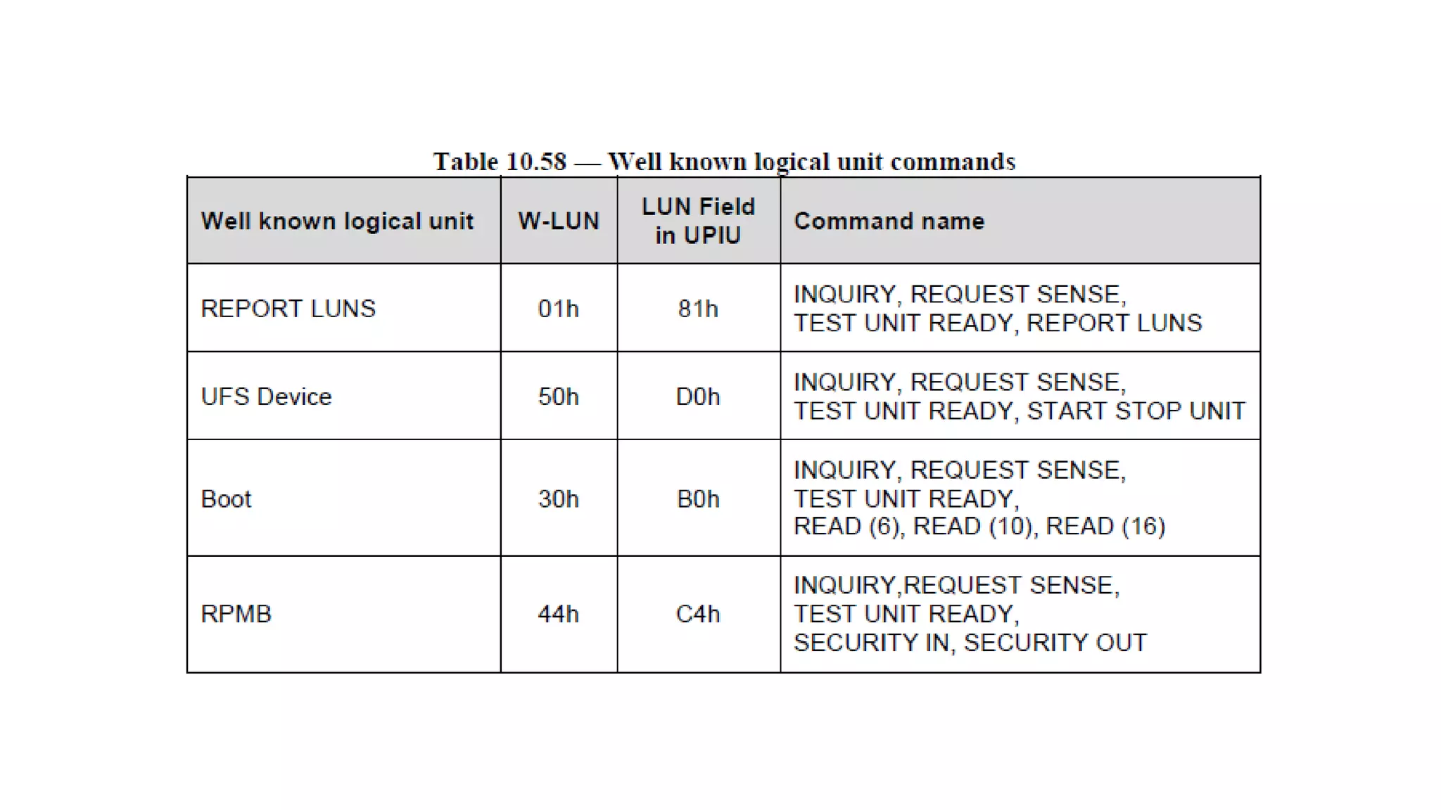
Universal Flash Storage (UFS) is a NAND flash storage specification developed by JEDEC that improves on eMMC. UFS uses a serial interface for faster read/write speeds compared to eMMC's parallel interface. It has a layered architecture including a device manager layer, UFS command set layer, UFS transport protocol layer, and UFS interconnect layer. The document discusses these layers and covers UFS features like logical units, command formats like UPIU, and SCSI commands supported in UFS including MODE SELECT, MODE SENSE, and READ/WRITE commands.


![[144]mobile앱에서 효율적인 storage 접근 방법](https://cdn.slidesharecdn.com/ss_thumbnails/144mobilestorage-150914022925-lva1-app6891-thumbnail.jpg?width=640&height=640&fit=bounds)
