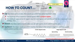
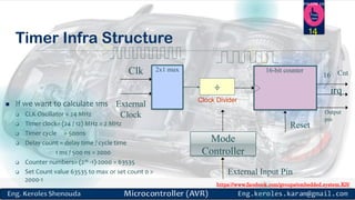
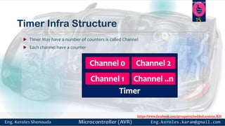
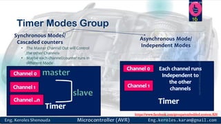
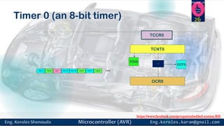
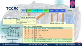
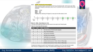
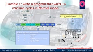
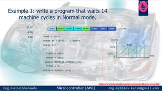
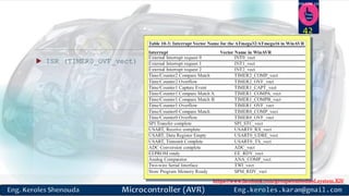
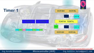
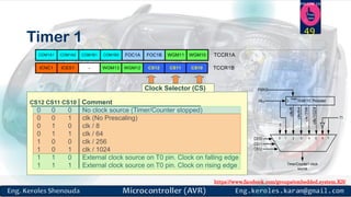
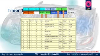
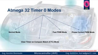
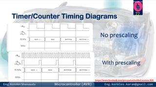
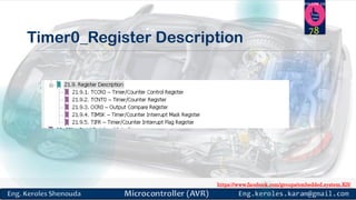
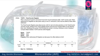
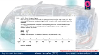
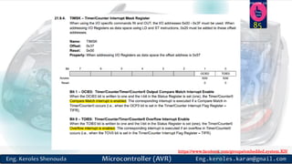
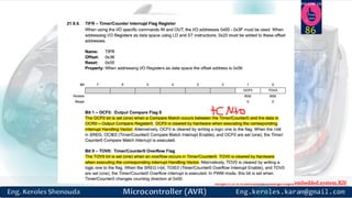
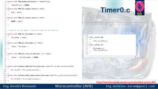
https://www.facebook.com/groups/embedded.system.KS/
Follow us
Press
here
Embedded System
PART 5 (Timers)
ENG.KEROLES SHENOUDA
1
https://www.facebook.com/groups/embedded.system.KS/
Follow us
Press
here
Previous Session
covered …..
2
https://www.facebook.com/groups/embedded.system.KS/
Follow us
Press
here
Previous session 3
Covered those points
Interrupt
definition &
Servicing
Interrupts
IVT & ISR &
Vector Section
Polling vs.
Interrupt
Steps in
executing an
interrupt
Sequential
interrupt
processing VS
Nested interrupt
processing
Types of
Interrupts
Interrupt
Controller
Examples On
Interrupt
Controllers
Interrupt
Controller On
Atmega32
https://www.facebook.com/groups/embedded.system.KS/
Follow us
Press
here
How to generate assembly
file from elf image
(executable file)?
4
https://www.facebook.com/groups/embedded.system.KS/
Follow us
Press
here
Disable auto generate MakeFile
5
https://www.facebook.com/groups/embedded.system.KS/
Follow us
Press
here
Add this command on your
MakeFile
6
https://www.facebook.com/groups/embedded.system.KS/
Follow us
Press
here
Then Build you will see
ATMEGA32_Drivers_disassemply.txt is generated
7
Now you can see the
_Vectors section
https://www.facebook.com/groups/embedded.system.KS/
Follow us
Press
here
8
Interrupts & Timers
 Interrupt Latency:
Time from event to execution of service routine
 Interrupt Response Time:
Interrupt latency + Time for service routine
 Interrupt Termination:
Time taken after interrupt service routine
https://www.facebook.com/groups/embedded.system.KS/
Follow us
Press
here
Timer
EMBEDDED MODULE (GENERIC CONCEPT)
9
https://www.facebook.com/groups/embedded.system.KS/
Follow us
Press
here
What is a timer ?
 At a high level, a timer is just a “Counter” register that counts up or down automatically.
 A Counter can be used to keep track of time. It can increment/decrement a count register based on a
clock and to check if the count has reached some value and trigger an action.
 17 Peripherals
 Timers generally have a resolution of 8 or 16 or 32 Bits.
 So a 8 bit timer is 8Bits wide so capable of holding value within 0-255. But this register has a magical
property ! Its value increases/decreases automatically at a predefined rate (supplied by user).
 This is the timer clock. And this operation does not need CPU’s attention.
10
https://www.facebook.com/groups/embedded.system.KS/
Follow us
Press
here
Counters
 Counter: like a timer, but counts pulses on a general input signal
rather than clock
 e.g., count cars passing over a sensor
 Can often configure device as either a timer or counter
11
16-bit up counter
Clk
16
Cnt_in
2x1 mux
Mode
Timer/counter
Top
Reset
Cnt
https://www.facebook.com/groups/embedded.system.KS/
Follow us
Press
here
HOW TO COUNT…
 Up: the timer starts at zero, then counts up until it hits some maximum value.
 The maximum value is stored in a special register called a compare register.
 The maximum value can be the largest value the timer register can hold (like 0xFF for 1Byte Counter) or some
arbitrary value.
 Down: the timer starts at some value you set and counts down until it reaches zero.
 Up/Down: the timer counts up until it reaches the value in the compare register, and then counts
down until it reaches zero.
12
Counter register
External
source
Oscillator
Counter/Timer
COUT
0
1
Flag
https://www.facebook.com/groups/embedded.system.KS/
Follow us
Press
here
Timer used to …
 timer will produce a regular output with the same accuracy as the input clock.
This output could be used to generate a periodic interrupt like a real-time
operating system (RTOS) timer tick.
 provide a baud rate clock to a UART.
 drive any device that requires a regular pulse.
 Delay generating
 Counting
 Wave-form generating
 Capturing
13
https://www.facebook.com/groups/embedded.system.KS/
Follow us
Press
here
Timer Infra Structure
14
 If we want to calculate 1ms
 CLK Oscillator = 24 MHz
 Timer clock= (24 / 12) MHz = 2 MHz
 Timer cycle = 500ns
 Delay count = delay time / cycle time
1 ms / 500 ns = 2000
 Counter numbers= (216 -1)-2000 = 63535
 Set Count value 63535 to max or set count 0 >
2000-1
16-bit counterClk 16
External
Clock
2x1 mux
Mode
Controller
irq
Reset
Cnt
÷
Clock Divider
External Input Pin
Output
pin
https://www.facebook.com/groups/embedded.system.KS/
Follow us
Press
here
Timer Infra Structure
 Timer May have a number of counters is called Channel
 Each channel have a counter
15
https://www.facebook.com/groups/embedded.system.KS/
Follow us
Press
here
Timer Modes Group
16
Synchronous Modes/
Cascaded counters
Asynchronous Mode/
Independent Modes• The Master Channel Out will Control
the other Channels
• Maybe each channel/counter runs in
different Mode
https://www.facebook.com/groups/embedded.system.KS/
Follow us
Press
here
Watchdog (WDOG)
17
https://www.facebook.com/groups/embedded.system.KS/
Follow us
Press
here
Watchdog (WDOG)
 WDOG is intended to be used to apply a reset to a system in the event of a
failure.
 WDOG consists of counter with a programmable timeout interval that has the
capability to generate an interrupt and a reset signal on timing out.
 For normal operation – the software has to ensure that the counter never
reaches zero (“kicking the dog”)
 Usually WDOG interrupt is set with highest priority.
18
https://www.facebook.com/groups/embedded.system.KS/
Follow us
Press
here
Timers in ATMEGA32
TWO 8-BIT TIMERS AND ONE 16-BIT TIMER IN ATMEGA32
19
https://www.facebook.com/groups/embedded.system.KS/
Follow us
Press
here
Timers in ATMEGA32
 TCNTn (Timer/Counter register)
 TOVn (Timer Overflow flag)
 TCCRn (Timer Counter control register)
 OCRn (output compare register)
 OCFn (output compare match flag)
20
Flag
Counter register
External
source
Oscillator
Counter/Timer
TCNTn
TCCRn
TOVn
OCRn
= OCFn
Comment:
All of the timer registers are byte-addressable I/O
registers
https://www.facebook.com/groups/embedded.system.KS/
Follow us
Press
here
Atmega 32 Timer 0 Modes
Normal Mode
Clear Timer on Compare Match (CTC) Mode
Fast PWM Mode Phase Correct PWM Mode
21
https://www.facebook.com/groups/embedded.system.KS/
Follow us
Press
here
Hand Writing Notes
22
https://www.facebook.com/groups/embedded.system.KS/
Follow us
Press
here
Hand Writing Notes
23
https://www.facebook.com/groups/embedded.system.KS/
Follow us
Press
here
Hand Writing Notes
24
https://www.facebook.com/groups/embedded.system.KS/
Follow us
Press
here
Normal Mode
 The simplest mode of operation is the Normal mode (WGM01:0 = 0).
 In this mode the counting direction is always up (incrementing), and no counter clear is performed.
 The counter simply overruns when it passes its maximum 8-bit value (TOP = 0xFF) and then restarts from
the bottom (0x00).
 In normal operation the Timer/Counter Overflow Flag (TOV0) will be set in the same timer clock cycle as the
TCNT0 becomes zero. The TOV0 Flag in this case behaves like a ninth bit, except that it is only set, not
cleared. However, combined with the timer overflow interrupt that automatically clears the TOV0 Flag,
 the timer resolution can be increased by software. There are no special cases to consider in the Normal
mode, a new counter value can be written anytime.
 The Output Compare unit can be used to generate interrupts at some given time. Using the Output
Compare to generate waveforms in Normal mode is not recommended, since this will occupy too much
ofthe CPU time.
25
https://www.facebook.com/groups/embedded.system.KS/
Follow us
Press
here
OCF2 TOV2 ICF1 OCF1A OCF1B TOV1 OCF0 TOV0 TIFR
TCNT0
TCCR0
TOV0
OCR0
= OCF0
Timer 0 (an 8-bit timer) 26
https://www.facebook.com/groups/embedded.system.KS/
Follow us
Press
here
TCCR0 COM01WGM00FOC0 COM00 CS02 CS01 CS00 TCCR0WGM01
CS02 CS01 CS00 Comment
0 0 0 No clock source (Timer/Counter stopped)
0 0 1 clk (No Prescaling)
0 1 0 clk / 8
0 1 1 clk / 64
1 0 0 clk / 256
1 0 1 clk / 1024
1 1 0 External clock source on T0 pin. Clock on falling edge
1 1 1 External clock source on T0 pin. Clock on rising edge
Clock Selector (CS)
WGM00 WGM01 Comment
0 0 Normal
0 1 CTC (Clear Timer on Compare Match)
1 0 PWM, phase correct
1 1 Fast PWM
Timer Mode (WGM)
10-bit T/C Prescaler
Clear
0
CS00
CS01
CS02
T0
clkIO
PSR10
Timer/Counter0 clock
source
clk/1024
clk/256
clk/64
clk/8
0 1 2 3 4 5 6 7
27
https://www.facebook.com/groups/embedded.system.KS/
Follow us
Press
here
28
https://www.facebook.com/groups/embedded.system.KS/
Follow us
Press
here
29
TCCR0
https://www.facebook.com/groups/embedded.system.KS/
Follow us
Press
here
0xFF
TCNT0
0
TOVTOV TOV
time
0TOV0:
1
FE
FF
TOV0 = 1
2
1
0
Normal Mode 30
https://www.facebook.com/groups/embedded.system.KS/
Follow us
Press
here
$100 == 256
-$0E
$F2
14 = $0E
COM01WGM00FOC0 COM00 CS02 CS01 CS00 TCCR0WGM01
0 0 10 0
Counter Register
COUT
UP Load
8
$F2
10-bit T/C Prescaler
Clear
0
CS00
CS01
CS02
T0
clkIO
PSR10
Timer/Counter0 clock
source
clk/1024
clk/256
clk/64
clk/8
0 1 2 3 4 5 6 7
https://www.facebook.com/groups/embedded.system.KS/
Follow us
Press
here
Example 1: write a program that waits 14
machine cycles in Normal mode.
DDRB = 1<<5;
PORTB &= ~(1<<5); //PB5=0
while (1)
{
TCNT0 = 0xF2;
TCCR0 = 0x01;
while((TIFR&(1<<TOV0))==0);
TCCR0 = 0;
PORTB = PORTB^(1<<5);
}
COM01WGM00FOC0 COM00 CS02 CS01 CS00 TCCR0WGM01
$100
-$0E
$F2
0xFF
TCNT0
0
TOV
time
0xF2
https://www.facebook.com/groups/embedded.system.KS/
Follow us
Press
here
How to calculate the delay generated
by the timer?
 1) Calculate how much a machine clock = 1/f
 2) Calculate how many machine clocks it waits.
 3) Delay = T * number of machine cycles
https://www.facebook.com/groups/embedded.system.KS/
Follow us
Press
here
Example 1:if frequency 10 MHZ
Solution 1 (inaccurate):
1) Calculating T:
T = 1/f = 1/10M = 0.1µs
2) Calculating number of machine cycles:
$100
-$F2
$0E = 14
3) Calculating delay
14 * 0.1µs = 1.4 0µs
https://www.facebook.com/groups/embedded.system.KS/
Follow us
Press
here
Generating Large Delays
Using loop
Prescaler
Bigger counters (Counter Register width)
35
10-bit T/C Prescaler
Clear
0
CS00
CS01
CS02
T0
clkIO
PSR10
Timer/Counter0 clock
source
clk/1024
clk/256
clk/64
clk/8
0 1 2 3 4 5 6 7
https://www.facebook.com/groups/embedded.system.KS/
Follow us
Press
here
Clear Timer on Compare Match
(CTC) Mode
 In Clear Timer on Compare or CTC mode (WGM01:0 = 2), the OCR0 Register is used to manipulate the
counter resolution. In CTC mode the counter is cleared to zero when the counter value (TCNT0) matches
the OCR0. The OCR0 defines the top value for the counter, hence also its resolution. This mode allows
greater control of the Compare Match output frequency. It also simplifies the operation of counting
external events.
The timing diagram for the CTC mode is shown in the figure below. The counter value (TCNT0) increases
until a Compare Match occurs between TCNT0 and OCR0, and then counter (TCNT0) is cleared.
36
https://www.facebook.com/groups/embedded.system.KS/
Follow us
Press
here
CTC (Clear Timer on Compare match) mode
TCNT0
0
OCF0OCF0 OCF0
time
0TOV0:
0
1
2
xx
TOV0 = no change
OCF0 = 1
OCR0
OCR0
0OCF0:
1
0xFF
37
https://www.facebook.com/groups/embedded.system.KS/
Follow us
Press
here
TIFR 38
https://www.facebook.com/groups/embedded.system.KS/
Follow us
Press
here
TIMSK 39
https://www.facebook.com/groups/embedded.system.KS/
Follow us
Press
here
Example 2: toggle led each 5 µs if you have a
frequency = XTAL = 10 MHZ
by Using compare match mode
 Because XTAL = 10 MHz, the counter counts up
every 0.1 µs. This means that we need 5 µs / 0.1
µs = 50 clocks. Therefore, we have OCR0= 49.
DDRB |= 1<<3;
PORTB &= ~(1<<3);
while (1)
{
OCR0 = 49;
TCCR0 = 0x09;
while((TIFR&(1<<OCF0))==0);
TCCR0 = 0; //stop timer0
PORTB.3 = ~PORTB.3;
}
COM01WGM00FOC0 COM00 CS02 CS01 CS00 TCCR0WGM01
40
https://www.facebook.com/groups/embedded.system.KS/
Follow us
Press
here
Timer Lab 1 (OVF) interrupt
 Write a program uses Timer0 to
generate a square wave on pin
PORTB.5, while at the same time
data is being transferred from
PORTC to PORTD. +5
PORTCPORTD
88
PORTB.5
ATmega32
41
https://www.facebook.com/groups/embedded.system.KS/
Follow us
Press
here
 ISR (TIMER0_OVF_vect) //ISR for Timer0 overflow
42
https://www.facebook.com/groups/embedded.system.KS/
Follow us
Press
here
 using Timer0 and CTC mode generate a square wave on pin
PORTB.5, while at the same time data is being transferred
from PORTC to PORTD.
 with 100 microS
Timer Lab 2 compare match interrupt
Time (µS)
44
F =1 MHZ
100*10^-6 / 10^-6 = Counter Numbers = 100
Compare Match = 100 – 1 =99 (start from 0 to 99)
https://www.facebook.com/groups/embedded.system.KS/
Follow us
Press
here
Timer2
 Timer0  Timer2
OCF2 TOV2 ICF1 OCF1A OCF1B TOV1 OCF0 TOV0 TIFR
TCNT2
TCCR2
TOV2
OCR2
= OCF2
TCNT0
TCCR0
TOV0
OCR0
= OCF0
46
https://www.facebook.com/groups/embedded.system.KS/
Follow us
Press
here
The difference between Timer0 and
Timer2
 Timer0  Timer2
CS02 CS01 CS00 Comment
0 0 0 Timer/Counter stopped
0 0 1 clk (No Prescaling)
0 1 0 clk / 8
0 1 1 clk / 64
1 0 0 clk / 256
1 0 1 clk / 1024
1 1 0 External clock (falling edge)
1 1 1 External clock (rising edge)
CS22 CS21 CS20 Comment
0 0 0 Timer/Counter stopped
0 0 1 clk (No Prescaling)
0 1 0 clk / 8
0 1 1 clk / 32
1 0 0 clk / 64
1 0 1 clk / 128
1 1 0 clk / 256
1 1 1 clk / 1024
47
https://www.facebook.com/groups/embedded.system.KS/
Follow us
Press
here
Timer 1
OCF2 TOV2 ICF1 OCF1A OCF1B TOV1 OCF0 TOV0 TIFR
TCNT1H TCNT1LTCCR1B
TOV1
OCR1AH OCR1AL
= OCF1A
= OCF1B
OCR1BH OCR1BL
TCCR1A
48
https://www.facebook.com/groups/embedded.system.KS/
Follow us
Press
here
Timer 1
WGM13 CS12 CS11 CS10WGM12ICNC1 ICES1 - TCCR1B
CS12 CS11 CS10 Comment
0 0 0 No clock source (Timer/Counter stopped)
0 0 1 clk (No Prescaling)
0 1 0 clk / 8
0 1 1 clk / 64
1 0 0 clk / 256
1 0 1 clk / 1024
1 1 0 External clock source on T0 pin. Clock on falling edge
1 1 1 External clock source on T0 pin. Clock on rising edge
Clock Selector (CS)
COM1B1 WGM11FOC1BCOM1B0 WGM10FOC1ACOM1A0COM1A1 TCCR1A
10-bit T/C Prescaler
Clear
0
CS10
CS11
CS12
T1
clkIO
PSR10
Timer/Counter1 clock
source
clk/1024
clk/256
clk/64
clk/8
0 1 2 3 4 5 6 7
49
https://www.facebook.com/groups/embedded.system.KS/
Follow us
Press
here
Timer 1 WGM13 CS12 CS11 CS10WGM12ICNC1 ICES1 - TCCR1B
COM1B1 WGM11FOC1BCOM1B0 WGM10FOC1ACOM1A0COM1A1 TCCR1A 50
https://www.facebook.com/groups/embedded.system.KS/
Follow us
Press
here
PWM (pulse width
Modulation)
51
https://www.facebook.com/groups/embedded.system.KS/
Follow us
Press
here
What is PWM ?
 A PWM Signal is a periodic rectangular pulse.
Frequency = 1/T
Duty Cycle = (T_ON/T)
 Pulse width modulation (PWM) is a powerful technique for controlling analog
circuits with a microprocessor's digital outputs. PWM is employed in a wide
variety of applications, ranging from measurement and communications to
power control and conversion.
52
https://www.facebook.com/groups/embedded.system.KS/
Follow us
Press
here
What is need of PWM?
 PWM is mainly used for controlling the speed of DC motors . By pulse width
modulation we can get a variable voltage digitally, that is we get voltages
between 0 and VCC by switching the VCC on and off periodically . Other
applications are fading Led , getting different tones in Buzzer,Contolling the
degree of rotation of Servo motor .
53
https://www.facebook.com/groups/embedded.system.KS/
Follow us
Press
here
How Does A Servo Motor Work?
 Usually a servomotor turns 90° in either direction, i.e. maximum movement
can be 180°
 Three wires are taken out of a servo: positive, ground and control wire.
 A servo motor is controlled by sending a Pulse Width Modulated (PWM) signal
through the control wire. A pulse is sent every 20 milliseconds.
 Width of the pulses determine the position of the shaft. For example, a pulse
of
1ms will move the shaft anticlockwise at -90°, a pulse of 1.5ms will move the
shaft at the neutral position that 0° and a pulse of 2ms will move the shaft
clockwise at +90
54
https://www.facebook.com/groups/embedded.system.KS/
Follow us
Press
here
How Does A Servo Motor Work?
 Width of the pulses determine the position of the shaft. For example, a pulse of
1ms will move the shaft anticlockwise at -90°, a pulse of 1.5ms will move the shaft at the neutral position
that 0° and a pulse of 2ms will move the shaft clockwise at +90
55
https://www.facebook.com/groups/embedded.system.KS/
Follow us
Press
here
Servo motor
 Servo motor works on PWM (Pulse width
modulation) principle, means its angle of rotation is
controlled by the duration of applied pulse to its
Control PIN. Basically servo motor is made up of
DC motor which is controlled by a variable resistor
(potentiometer) and some gears
56
https://www.facebook.com/groups/embedded.system.KS/
Follow us
Press
here
Servo motor (another degree
range)(Motor-PWMSERVO in ISIS)
 Servo motor can be rotated from 0 to 180 degree,
but it can go up to 210 degree, depending on the
manufacturing. This degree of rotation can be
controlled by applying the Electrical Pulse of proper
width, to its Control pin. Servo checks the pulse in
every 20 milliseconds. Pulse of 1 ms (1 millisecond)
width can rotate servo to 0 degree, 1.5ms can rotate
to 90 degree (neutral position) and 2 ms pulse can
rotate it to 180 degree.
57
https://www.facebook.com/groups/embedded.system.KS/
Follow us
Press
here
Lab1/Test Servo Motor By Atmega 32
 With out any timer, run a servo Motor (Motor-PWMSERVO ) in ISIS
 Angle 0,90 and 180 as shown below
58
https://www.facebook.com/groups/embedded.system.KS/
Follow us
Press
here
Lab1/Test Servo Motor By Atmega 32
 With out any timer, run a servo Motor (Motor-PWMSERVO ) in ISIS
 Angle 0,90 and 180 as shown below
59
https://www.facebook.com/groups/embedded.system.KS/
Follow us
Press
here
Lab1/Test Servo Motor By Atmega 32
 With out any timer, run a servo Motor (Motor-PWMSERVO ) in ISIS
 Angle 0,90 and 180 as shown below
60
https://www.facebook.com/groups/embedded.system.KS/
Follow us
Press
here
Lab1/Test
Servo Motor
By Atmega 32
Solution
61
https://www.facebook.com/groups/embedded.system.KS/
Follow us
Press
here
DC Motor
 This DC or direct current motor works on the principal, when a current
carrying conductor is placed in a magnetic field, it experiences a torque and
has a tendency to move.
62
https://www.facebook.com/groups/embedded.system.KS/
Follow us
Press
here
Lab2/ write embedded C Code
without timer to run two DC Motors
 First DC Motor Connect to PD0 (run Clockwise)
 Second DC Motor Connect to PD1 (run Anticlockwise)
 Sequence (Motor 1 run) > Motor1 stop & Motor 2 run
And so on
 Choose the time you prefer
63
https://www.facebook.com/groups/embedded.system.KS/
Follow us
Press
here
Lab2/ sequence
64
https://www.facebook.com/groups/embedded.system.KS/
Follow us
Press
here
LAB2/Solution
65
https://www.facebook.com/groups/embedded.system.KS/
Follow us
Press
here
We can’t connect a DC Motor
directly to a microcontroller ?
 A microcontroller can’t supply the current required for the working of DC
Motor. ATmega32 Microcontroller can source or sink currents up to 40mA but
a DC Motor needs current very much more than that.
 The negative voltages created due to the back emf of the motor may affect
the proper functioning of the microcontroller.
 You may need to control the direction of rotation of the motor by changing
the polarity of the motor supply.
 The operating voltage of the DC Motor may be much higher than the
operating voltage of the microcontroller.
66
https://www.facebook.com/groups/embedded.system.KS/
Follow us
Press
here
L293D
 To solve these problems you may use transistorized H Bridge in which
freewheeling diodes are used to avoid problems due to back emf. Thus it requires
minimum four transistors, diodes and resistors for each motor. It is better to use
readymade ICs such as L293D or L293instead of making your own H Bridge, which
simplifies your project.
 L293D is a Quadruple Half H-Bridge driver commonly used for motor driving. We
needn’t connect any transistors, resistors or freewheeling diodes. All the four
outputs of this IC are TTL compatible and output clamp diodes are provided to
drive inductive loads. L293D can provide up to 600mA current, in the voltage
raging from 4.5 to 36v. L293 is a similar IC which can provide up to 1A in the same
voltage range.
 L293 or L293D contains four Half H Bridge drivers and are enabled in pairs. Input
EN1 is used to enable pair 1 (IN1-OUT1, IN2-OUT2) and input EN2 is used to enable
pair 2 (IN3-OUT3, IN4-OUT4). We can drive two DC Motors with one L293D, but
here for demonstration we are using only one. You can connect second DC Motor
to driver pair 2 according to your needs.
67
https://www.facebook.com/groups/embedded.system.KS/
Follow us
Press
here
Control Signals and Motor Status
PC0/IN1 PC1/IN2 Motor Status
LOW LOW Stops
LOW HIGH Clockwise
HIGH LOW Anti-Clockwise
HIGH HIGH Stops
68
https://www.facebook.com/groups/embedded.system.KS/
Follow us
Press
here
If we can generate PWM by GPIO and Delay,
Why we need to use TIMER Module to generate PWM ?
69
https://www.facebook.com/groups/embedded.system.KS/
Follow us
Press
here
Atmega 32 Timer 0 Modes
Normal Mode
Clear Timer on Compare Match (CTC) Mode
Fast PWM Mode Phase Correct PWM Mode
70
https://www.facebook.com/groups/embedded.system.KS/
Follow us
Press
here
Hand Writing Notes: we took it on the previous
Lecture 71
https://www.facebook.com/groups/embedded.system.KS/
Follow us
Press
here
Request time equation 72
Some Times
We need t used
SW Counters (looping)
Increment SW Counter
after each Timer ISR
That make us to increase
the Required delay range
https://www.facebook.com/groups/embedded.system.KS/
Follow us
Press
here
Normal Mode
 The simplest mode of operation is the Normal mode (WGM01:0 = 0).
 In this mode the counting direction is always up (incrementing), and no counter clear is performed.
 The counter simply overruns when it passes its maximum 8-bit value (TOP = 0xFF) and then restarts from
the bottom (0x00).
 In normal operation the Timer/Counter Overflow Flag (TOV0) will be set in the same timer clock cycle as the
TCNT0 becomes zero. The TOV0 Flag in this case behaves like a ninth bit, except that it is only set, not
cleared. However, combined with the timer overflow interrupt that automatically clears the TOV0 Flag,
 the timer resolution can be increased by software. There are no special cases to consider in the Normal
mode, a new counter value can be written anytime.
 The Output Compare unit can be used to generate interrupts at some given time. Using the Output
Compare to generate waveforms in Normal mode is not recommended, since this will occupy too much
ofthe CPU time.
73
https://www.facebook.com/groups/embedded.system.KS/
Follow us
Press
here
Clear Timer on Compare Match
(CTC) Mode
 In Clear Timer on Compare or CTC mode (WGM01:0 = 2), the OCR0 Register is used to manipulate the
counter resolution. In CTC mode the counter is cleared to zero when the counter value (TCNT0) matches
the OCR0. The OCR0 defines the top value for the counter, hence also its resolution. This mode allows
greater control of the Compare Match output frequency. It also simplifies the operation of counting
external events.
The timing diagram for the CTC mode is shown in the figure below. The counter value (TCNT0) increases
until a Compare Match occurs between TCNT0 and OCR0, and then counter (TCNT0) is cleared.
74
https://www.facebook.com/groups/embedded.system.KS/
Follow us
Press
here
Fast PWM Mode
75
https://www.facebook.com/groups/embedded.system.KS/
Follow us
Press
here
Phase Correct PWM Mode, Timing
Diagram
76
https://www.facebook.com/groups/embedded.system.KS/
Follow us
Press
here
Timer/Counter Timing Diagrams
No prescaling
With prescaling
77
https://www.facebook.com/groups/embedded.system.KS/
Follow us
Press
here
Timer0_Register Description
78
https://www.facebook.com/groups/embedded.system.KS/
Follow us
Press
here
79
https://www.facebook.com/groups/embedded.system.KS/
Follow us
Press
here
80
https://www.facebook.com/groups/embedded.system.KS/
Follow us
Press
here
81
https://www.facebook.com/groups/embedded.system.KS/
Follow us
Press
here
82
https://www.facebook.com/groups/embedded.system.KS/
Follow us
Press
here
83
https://www.facebook.com/groups/embedded.system.KS/
Follow us
Press
here
84
https://www.facebook.com/groups/embedded.system.KS/
Follow us
Press
here
85
https://www.facebook.com/groups/embedded.system.KS/
Follow us
Press
here
86
https://www.facebook.com/groups/embedded.system.KS/
Follow us
Press
here
Assignments
Repeat Lab1/2 by using
Timer0
87
https://www.facebook.com/groups/embedded.system.KS/
Follow us
Press
here
How to write Driver
for Timer0
88
https://www.facebook.com/groups/embedded.system.KS/
Follow us
Press
here
Driver
89
https://www.facebook.com/groups/embedded.system.KS/
Follow us
Press
here
Timer0 Driver
HTTPS://GITHUB.COM/KEROLES/EMBEDDED_SYSTEM/TREE/MASTER/ATMEGA32
_DRIVERS/ATMEGA32_DRIVERS/TIMER0
90
Kindly you can find it on
https://www.facebook.com/groups/embedded.system.KS/
Follow us
Press
here
Timer0.h 91
https://www.facebook.com/groups/embedded.system.KS/
Follow us
Press
here
Timer0.h 92
https://www.facebook.com/groups/embedded.system.KS/
Follow us
Press
here
Timer0.h
93
https://www.facebook.com/groups/embedded.system.KS/
Follow us
Press
here
Timer0.c 94
https://www.facebook.com/groups/embedded.system.KS/
Follow us
Press
here
Timer0.c 95
https://www.facebook.com/groups/embedded.system.KS/
Follow us
Press
here
Timer0.c 96
https://www.facebook.com/groups/embedded.system.KS/
Follow us
Press
here
Assignment
97
https://www.facebook.com/groups/embedded.system.KS/
Follow us
Press
here
Assignment 1
 Repeat the Servo/DC Motor Labs by Using the Timer
98
https://www.facebook.com/groups/embedded.system.KS/
Follow us
Press
here
Assignment 2
 Complete the Timer0 Driver to Support the other Modes.
99
https://www.facebook.com/groups/embedded.system.KS/
Follow us
Press
here
References
 http://techdifferences.com/difference-between-interrupt-and-polling-in-
os.html
 http://www.bogotobogo.com/Embedded/hardware_interrupt_software_inter
rupt_latency_irq_vs_fiq.php
 Preventing Interrupt Overload Presented by Jiyong Park Seoul National
University, Korea 2005. 2. 22. John Regehr, Usit Duogsaa, School of
Computing, University.
 First Steps Embedded Systems Byte Craft Limited reference
 COMPUTER ORGANIZATION AND ARCHITECTURE DESIGNING FOR
PERFORMANCE EIGHTH EDITION William Stallings
 Getting Started with the Tiva™ TM4C123G LaunchPad Workshop
100
https://www.facebook.com/groups/embedded.system.KS/
Follow us
Press
here
References
 Tiva™ TM4C123GH6PM Microcontroller DATA SHEET
 Interrupts and Exceptions COMS W6998 Spring 2010
 THE AVR MICROCONTROLLER. AND EMBEDDED SYSTEMS Using Assembly and C.
Muhammad Ali Mazidi.
101
https://www.facebook.com/groups/embedded.system.KS/
Follow us
Press
here
References
 https://docs.google.com/viewer?a=v&pid=sites&srcid=ZmtlLnV0bS5teXxyaWR6dW
FuLXMtd2Vic2l0ZXxneDo2ODU0NzlkM2JkOTg4MjRk
 http://www.avrprojects.net/index.php/avr-projects/sensors/38-humidity-and-
temperature-sensor-dht11?showall=&start=1
 http://www.cse.wustl.edu/~lu/cse467s/slides/dsp.pdf
 http://www.avr-tutorials.com/
 Microprocessor: ATmega32 (SEE3223-10)
http://ridzuan.fke.utm.my/microprocessor-atmega32-see3223-10
 http://circuitdigest.com/article/what-is-the-difference-between-microprocessor-
and-microcontroller
 AVR Microcontroller and Embedded Systems: Using Assembly and C (Pearson
Custom Electronics Technology) 1st Edition
https://www.amazon.com/AVR-Microcontroller-Embedded-Systems-
Electronics/dp/0138003319
102
https://www.facebook.com/groups/embedded.system.KS/
Follow us
Press
here
103

Microcontroller part 5