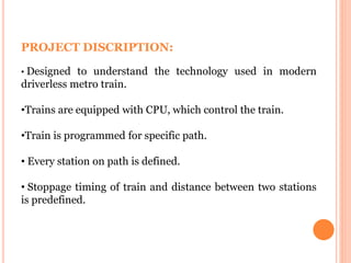
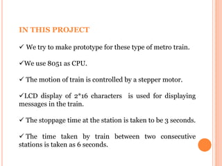
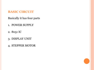
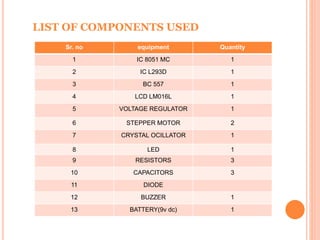
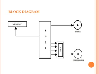
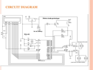
PRESENTED BY: GUIDED BY:
AJAY BHURIYA Prof. SANGEETA G C
RANJITSINH PARMAR
ABHISHEK KUSHWAHA
PROJECT DISCRIPTION:
• Designed to understand the technology used in modern
driverless metro train.
•Trains are equipped with CPU, which control the train.
•Train is programmed for specific path.
• Every station on path is defined.
• Stoppage timing of train and distance between two stations
is predefined.
IN THIS PROJECT
 We try to make prototype for these type of metro train.
We use 8051 as CPU.
 The motion of train is controlled by a stepper motor.
LCD display of 2*16 characters is used for displaying
messages in the train.
 The stoppage time at the station is taken to be 3 seconds.
 The time taken by train between two consecutive
stations is taken as 6 seconds.
LEDs are used as Indicators to show the train direction
i.e. UP and DOWN path.
It also have BUZZER system. As train is going to leave a
station, buzzer blows.
It also have an emergency brake system due to which
train stops as soon as brakes applied.
Can resume journey after emergency situation is over.
BASIC CIRCUIT
Basically it has four parts
1. POWER SUPPLY
2. 8051 IC
3. DISPLAY UNIT
4. STEPPER MOTOR
LIST OF COMPONENTS USED
Sr. no equipment Quantity
1 IC 8051 MC 1
2 IC L293D 1
3 BC 557 1
4 LCD LM016L 1
5 VOLTAGE REGULATOR 1
6 STEPPER MOTOR 2
7 CRYSTAL OCILLATOR 1
8 LED 1
9 RESISTORS 3
10 CAPACITORS 3
11 DIODE
12 BUZZER 1
13 BATTERY(9v dc) 1
BLOCK DIAGRAM
LCD INTERFACING WITH 8051
WHY WE USE ULN 2003?
•Microcontroller pins lack sufficient current to drive the
relay. They can provide a maximum of 1-2mA current.
While the stepper motor’s coil needs around 10mA to be
energized. For this reason, we place a driver so that
stepper motor can work efficiently.
CIRCUIT DIAGRAM
POWER SUPPLY CIRCUIT
WORKING OF PROJECT
•The 230 volts ac supply is converted into 9v by the
transformer used in power supply section.
•Then it is rectified by bridge rectifier made of diodes.
•Then the 9v is regulated by 7805.
•1000 micro farad capacitor is used to filter the DC
voltage.
•After supplying power to the circuit, it works according
to the programming done in 8051.
ADVANTAGE
• It breaks the barrier of time and cost.
• Lower expenditure on staff.
• Safer than traditional.
• Run more frequently.
• Turn over time at terminal is short.
• Lighter weight and energy efficient.
FUTURE SCOPE OF THIS PROJECT :
•This Project is useful in developing countries & this project
has a bright future as it is being used in countries like
Germany, France & Japan. This project helps us to control
train without a driver and the stations are shown on the LCD
so the passenger doesn’t have any type of difficulty. This
project will lead to increase in technological trends & this will
help the people in many ways.
CONCLUSION
We develop technology of driverless for metro trains,
which can be implement at national/international
level. It breaks the barrier of time and cost.
THANK YOU…..

Metro train

  • 1.
    PRESENTED BY: GUIDEDBY: AJAY BHURIYA Prof. SANGEETA G C RANJITSINH PARMAR ABHISHEK KUSHWAHA
  • 2.
    PROJECT DISCRIPTION: • Designedto understand the technology used in modern driverless metro train. •Trains are equipped with CPU, which control the train. •Train is programmed for specific path. • Every station on path is defined. • Stoppage timing of train and distance between two stations is predefined.
  • 3.
    IN THIS PROJECT We try to make prototype for these type of metro train. We use 8051 as CPU.  The motion of train is controlled by a stepper motor. LCD display of 2*16 characters is used for displaying messages in the train.  The stoppage time at the station is taken to be 3 seconds.  The time taken by train between two consecutive stations is taken as 6 seconds.
  • 4.
    LEDs are usedas Indicators to show the train direction i.e. UP and DOWN path. It also have BUZZER system. As train is going to leave a station, buzzer blows. It also have an emergency brake system due to which train stops as soon as brakes applied. Can resume journey after emergency situation is over.
  • 5.
    BASIC CIRCUIT Basically ithas four parts 1. POWER SUPPLY 2. 8051 IC 3. DISPLAY UNIT 4. STEPPER MOTOR
  • 6.
    LIST OF COMPONENTSUSED Sr. no equipment Quantity 1 IC 8051 MC 1 2 IC L293D 1 3 BC 557 1 4 LCD LM016L 1 5 VOLTAGE REGULATOR 1 6 STEPPER MOTOR 2 7 CRYSTAL OCILLATOR 1 8 LED 1 9 RESISTORS 3 10 CAPACITORS 3 11 DIODE 12 BUZZER 1 13 BATTERY(9v dc) 1
  • 7.
  • 8.
  • 9.
    WHY WE USEULN 2003? •Microcontroller pins lack sufficient current to drive the relay. They can provide a maximum of 1-2mA current. While the stepper motor’s coil needs around 10mA to be energized. For this reason, we place a driver so that stepper motor can work efficiently.
  • 10.
  • 11.
  • 12.
    WORKING OF PROJECT •The230 volts ac supply is converted into 9v by the transformer used in power supply section. •Then it is rectified by bridge rectifier made of diodes. •Then the 9v is regulated by 7805. •1000 micro farad capacitor is used to filter the DC voltage. •After supplying power to the circuit, it works according to the programming done in 8051.
  • 13.
    ADVANTAGE • It breaksthe barrier of time and cost. • Lower expenditure on staff. • Safer than traditional. • Run more frequently. • Turn over time at terminal is short. • Lighter weight and energy efficient.
  • 14.
    FUTURE SCOPE OFTHIS PROJECT : •This Project is useful in developing countries & this project has a bright future as it is being used in countries like Germany, France & Japan. This project helps us to control train without a driver and the stations are shown on the LCD so the passenger doesn’t have any type of difficulty. This project will lead to increase in technological trends & this will help the people in many ways.
  • 15.
    CONCLUSION We develop technologyof driverless for metro trains, which can be implement at national/international level. It breaks the barrier of time and cost.
  • 16.