Metro North, Dublin - Construction Explained
•
5 likes•2,139 views

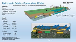
This document provides details on the proposed Metro North project in Dublin, Ireland, including a €2.4 billion budget. It outlines the 18km route, which includes 7.5km of tunnels, 2.7km of cut-and-cover tunnels, 2.25km of viaducts, and 5.5km at road level. There will be 15 stations, with 9 underground and 6 at road level. The presentation aims to provide an understanding of the construction, costs, and timeline to stakeholders and politicians. It includes information on tunnel boring machines, station excavation, concrete works, viaduct construction, and other aspects of the large infrastructure project.

Recommended
More Related Content
What's hot
What's hot (20)
Viewers also liked
Viewers also liked (20)
Similar to Metro North, Dublin - Construction Explained
Similar to Metro North, Dublin - Construction Explained (20)
More from David H Moloney
More from David H Moloney (9)
Recently uploaded
Recently uploaded (20)
Metro North, Dublin - Construction Explained
- 1. Metro North Dublin Ireland, Proposed – Construction €2.4bn Included Route Programme Graphic Tunnelling Construction Stations Construction Cost Details Lengths Overall 18 km Tunnel 7.5 km Cut & Cover 2.7 km Viaduct 2.25 km Road Level 5.5 km Stations 15 Nr. Underground 9 Nr. Road Level 6 Nr. Tunnels & Underground Stations Route 3D image to show Sequence, Method & Plant. David H Moloney 29th June 2017 Purpose of presentation to give the Public, Stakeholders and Politicians an understanding of the Construction, Cost and Timeline ⓒ David H Moloney Schematic Longitudinal Profile Project Execution Plan Details of how a Metro is constructed, and how the progress, safety and quality will be monitored and controlled.
- 3. Overview
- 4. Route of Metro North ⓒ David H Moloney
- 5. Schematic with Principal Quantities David H Moloney Schematic Longitudinal Profile ⓒ David H Moloney
- 6. Programme - Time Chainage Diagram ⓒ David H Moloney
- 7. Tunnels & Underground Stations TBM TBM Tunnel Tunnel TunnelViaduct Along Street Programme Animation ⓒ David H Moloney Schematic Longitudinal Profile
- 8. Cost Comparisons of Metro Projects Dubai Route 2020 UAE (To Start) Red Line North Doha Qatar (In Progress) Red Line South Doha Qatar ( In Progress) Metro North Dublin (Proposed) Dart Underground Dublin (Proposed) Port Tunnel Dublin (2005) Overall Cost €2,450 million €1,803 million €1,500 million €2,400 million €2,000 million ? €752 million Cost per km €158 million /k m €140 million / km €108 million / km €134 million / km €400 million / km ? €134 million / km Overall Length 15.5 km 13 km 14m 18 km 5 km 5.6 km Tunnel 4 km Single Tunnel 11.6 km Twin Tunnels 14 km Twin Tunnels 7.5 km Twin Tunnels 5 km Twin Tunnel 4.5 km Road Tunnel x 2 Cut & Cover 0 2.7 km 0 Elevated 10.5 km 2.2 km 0 Not applicable Road Level 0 5.5 km 0 Stations 7 Nr. 7 Nr. 5 Nr. 14 Nr. 3 Nr. Not applicable Capacity 13,000 Passengers per hour 19,800 Passengers per hour ? Not applicable ⓒ David H Moloney
- 9. Advantages of Rail Benefits of Metro to commuters 1. Time saving for commuters 4. Reduction in accident 2. Reliable and safe journey 5. Reduced fuel consumption 3. Reduction in atmospheric pollution 6. Reduced traffic congestion
- 11. Contractor’s Temporary Site Facilities ⓒ David H Moloney Brief Description Contractors Site facilities comprise: Offices, Canteens, Toilets, Drying Rooms, Stores, Plant Yard, generators and Workshops. GeneralItems
- 12. Concrete Batching Plant David H Moloney ⓒ David H Moloney Concrete batching plant comprises - concrete mixer, control cabin, silos for cement and fly ash, aggregate bins and conveyor belt system to feed the mixer. Also aggregate storage bays and water storage tanks. The mixing is computer controlled and has a dynamic screen display, showing the process. Material storage capacity to match two days concrete production
- 13. Quarry & Aggregate Production 3D image to show Sequence, Method & Plant. ⓒ David H Moloney
- 14. Reinforcement Cutting & Bending Yard David H Moloney ⓒ David H Moloney Reinforcement in 12 m lengths. Delivery in 3 ton Bundles Reinforcement cut to length by Shearing Machine Reinforcement Bent to Shape by Bending Machine Reinforcement that is cut and bent is Bundled for delivery to work site
- 15. Site Hoarding examples ⓒ David H Moloney GeneralItems
- 17. Weighbridge & Sheeting Access ⓒ David H Moloney GeneralItems
- 18. Sheet Pile Temporary Shaft ⓒ David H Moloney GeneralItems Brief Description Sheet Pile Temporary shaft is used to enable an excavation for a deep structure. The construction sequence is: Install sheet-piles. Excavate and install bracing. Excavate to final level. Construct concrete structure. Backfill, remove bracing and sheet-piles
- 19. Sheet Pile Temporary Shaft ⓒ David H Moloney GeneralItems 3D Animation to show Sequence
- 20. FalseworkGeneralItems Brief Description Falsework to support Bridge deck formwork
- 21. Dewatering ⓒ David H Moloney GeneralItems Brief Description Construction dewatering is the removal or drainage of groundwater and or surface / rain water usually by pumping to keep the works dry.
- 22. Dewatering ⓒ David H Moloney GeneralItems
- 23. Dewatering by Wellpoints ⓒ David H Moloney GeneralItems
- 24. Dust Suppression ⓒ David H Moloney GeneralItems
- 25. Temporary Fence type 2 ⓒ David H Moloney GeneralItems Brief Description Temporary fence on precast beam for airport.
- 26. Traffic Management ⓒ David H Moloney GeneralItems Brief Description Traffic management plans are necessary when working on or beside roads
- 27. Traffic Management - Realign Motorway under new Bridges ⓒ David H Moloney GeneralItems
- 28. Health, Safety & Environmental
- 29. Existing Underground Utilities ⓒ David H Moloney Earthworks Brief Description Before digging establish the location and route of underground utilities. Locator to find Utilities Spray Paint to mark pavement
- 30. Existing Underground Utilities & Overhead Cables - Safety Measures ⓒ David H Moloney Earthworks
- 32. HSE Monitoring & Reporting - Dashboard Dashboard is a single page, graphical representation of current HSE Issues and historical trends
- 33. Environmentally Friendly Site Air, Noise, Water & Soil Pollution
- 35. Geotechnical
- 36. Diaphragm Wall Construction - Sequence, Plant & Methods 3D image to show Sequence, Method & Plant. For construction details see my YouTube Channel ⓒ David H Moloney
- 37. Earthworks
- 38. Tunnels & Underground Stations 3D image to show Sequence, Method & Plant. David H Moloney ⓒ David H Moloney
- 39. Excavate & Load, Cart, Tip & Return Brief Description Cycle Time for 7km haulage distance using an Excavator 45 tonne weight and Dumper with a 40 tonne capacity, the cycle time is 34 minutes Earthworks 7 minutes 14 minutes 3 minutes 14 minutes 7 km 7 km
- 42. Rock Excavation Underground Excavate with Roadheader Drill & Fit Rock Bolts Spray Mortar as Lining Excavators with Rock Breaker & Rock Rotary Cutter Roadheader ⓒ David H Moloney Using Mining Techniques
- 43. Bed Rock - Type & Depth Ground Conditions The limestone bedrock is between 5 and 25 metres below ground level. The overlying deposits are generally boulder clay with thin layers of sand and gravel. The water table is between 2 and 4 metres below ground level. The Bedrock Geology Map of Ireland, gives the rock as limestone and mudstone, along the tunnel route.
- 44. Rock - Excavability Brief Description The excavability of rock depends mainly on the rock strength and the layer thickness. This diagram shows excavation methods for rock of various strengths and thicknesses, with a free face. ⓒ David H Moloney Earthworks
- 45. Station Excavation - Soil on Rock Situation Rock Nailing, Rock breaking & Excavation ⓒ David H Moloney
- 46. Concrete
- 47. Tunnel Wall Segments Casting Clean Mould Lift Precast Segment out of mould after 18 hours. Reinforcement fabricate Reinforcement into Mould Concreting Segment Storage Casting Cycle Time 24 hrs ⓒ David H Moloney
- 49. Reinforced Wall Construction Sequence ⓒ David H Moloney Concrete Brief Description The sequence to construct a reinforced concrete wall is as follows: Tie the reinforcement. Erect stop-ends and the wall shutters. Pour and vibrate the concrete mix. Remove the shutters after the concrete has hardened. . Cycle Time Pour per Day
- 50. Reinforced Wall Construction Sequence ⓒ David H Moloney Concrete
- 51. Reinforced Structure Construction Sequence ⓒ David H Moloney Concrete Brief Description The general sequence to construct a reinforced concrete tank is as follows- 1. Construct the floor and wall panels in a hit and miss pattern. 2. Construct the floor and wall corners and T shape panels. 3. Construct the roof working outwards from the back.
- 52. Reinforced Structure Construction Sequence David H Moloney ⓒ David H Moloney
- 53. Bridge & Post-tensioning Concrete Brief Description The sequence to post-tension a bridge deck is as follows; Fix the ducts and anchorages. Install the stressing strand. Concrete the deck. Stress the strands and lock at anchorages. Grout the ducts.
- 56. Bridge Construction Sequence David H Moloney Piling Surcharge Abutments Remove Surcharge Abutments Deck centre Post-tensioning Fascia & Waterproof deck Complete Bridge PiersOverview Deck Ends Images with Schematic 3D view, Photos & Timeline ⓒ David H Moloney
- 57. Post-tensioning Bridge Deck David H Moloney
- 58. Waterproofing Spray on System Miscellaneous
- 59. Waterproofing Spray on Tests Miscellaneous
- 60. Underground Stations David H Moloney ⓒ David H Moloney
- 61. Large Floor Concrete Pour
- 62. Rail Viaduct Concrete Brief Description Shown is the construction of a light rail viaduct where an overhead gantry was used to lift and place the precast concrete viaduct segments.
- 63. Viaduct Construction 3D image to show Sequence, Method & Plant. For construction details see my YouTube Channel David H Moloney ⓒ David H Moloney
- 64. Viaduct Construction David H Moloney ⓒ David H Moloney
- 65. Viaduct Segments Launching ⓒ David H Moloney
- 66. Viaduct Segments Casting David H Moloney Casting Method The concrete segments are manufactured using the short-line, match-casting method. Match-casting is when sequential segments are poured against the previous cast segment, this ensures that the segments will fit perfectly on site. Horizontal and vertical curves are achieved by setting the cast segment at a rotation in either or both axis to the mould used to cast the next segment. ⓒ David H Moloney
- 67. Viaduct Segments – Short-line, Match Casting Method David H MoloneyMatch-casting is when sequential segments are poured against the previous cast segment, this ensures that the segments will fit perfectly on site. Cycle Time 24 hrs
- 68. Piling
- 69. Piling Construction - Plant & Methods Brief Description Piling Plant, Equipment and Material; Crawler Crane, Piling Hammer, Temporary Casing, Piling Rig, Concrete Pump, Concrete Mixer Trucks, Tremie Pipe and Reinforcement Cage Piling
- 70. Piling Construction - Plant, Methods & SequencePiling
- 71. Piling Construction - Plant & MethodsPiling
- 72. Piling Construction - Vertical PilesPiling
- 73. Piling Construction - Raking PilesPiling
- 74. Piling Construction - Raking PilesPiling
- 75. Pile Load Test ⓒ David H Moloney Piling Brief Description A jack is used to load the pile in steps and gauges measure any settlement.
- 76. Secant Pile Construction - Sequence, Plant & Methods 3D image to show Sequence, Method & Plant. For construction details see my YouTube Channel ⓒ David H Moloney
- 77. Roads & Paving
- 79. Road Construction Sequence Animation
- 80. Tunnel
- 81. Tunnel Design Twin Tunnels single track with Cross passages at 250m intervals for emergency evacuation Tunnels in rock to avoid ground & building settlement. Depth 25 metres on average ⓒ David H Moloney
- 82. Cut & Cover Tunnel Construction Sequence -Traffic and utilities are diverted, excavate trench, construct & backfill to bury. To prevent the faces of the excavation from collapsing, different measures are used – batter the faces, diaphragm walls, secant piles or a combination of soil nailing and shotcreting.
- 83. Ramp Construction Sequence -Traffic and utilities are diverted, excavate, construct and backfill to sides. To prevent the faces of the excavation from collapsing, different measures are used – batter faces, diaphragm walls, secant piles or a combination of soil nailing and shotcreting. ⓒ David H Moloney
- 84. Tunnel Boring Machine (TBM) Cutting Head rotates to Dig Excavated material removed by conveyor belt Lifting muck to surface with skip Placing Concrete Segments
- 85. Tunnel Boring Machine (TBM) Cutting Head rotates 7 nr. Precast segments form rings that line the tunnel Excavated material removed by conveyor belt ⓒ David H Moloney
- 86. Tunnel Fit-out Rail, Electricals, Ventilation
- 87. Tunnel Fit-out Install Sleepers & Rails Concrete Batching Train for Floor Slab Drilling Machine for Utilities Brackets
- 88. Commissioning, Testing, Handover & Opening Purpose to test and ensure that everything (e.g. trains, escalators, lifts, ticket barriers) works as it should. ⓒ David H Moloney
- 90. Fencing ⓒ David H Moloney Sequence of Construction Clear Scrub & Grade ground Fix Corner & Strainer Posts Fix Intermediate Posts Fix Line Wire, Chain-link & Razer wire Concrete ground beam
- 91. Progress Monthly, Monitoring & Reporting - Dashboard Dashboard is a single page, graphical representation of current progress and historical trends
- 92. Histogram Charts for Resources & Outputs Concrete, Manpower, TBM, Manpower per Discipline Concrete per Location Numbers for each month of the Project Quantity for each month of the Project ⓒ David H Moloney
- 93. Plant & Equipment List & Worker’s Job Titles ⓒ David H Moloney
- 94. Organogram Brief Description Shown are the line and lateral relationships between the various team members and their relative position in the site organisation.
- 95. Other Projects
- 96. Luas – Dublin, Tram / Light Rail System Construction Sequence & Methods Install Traffic Control Fencing & Welfare Facilities Divert Underground Utilities Excavate Prepare Formation Reinforcement & Rails Paving Paving Information Sign Trams in Operation Trams in Operation Reinforcement & Rails ⓒ David H Moloney
- 97. Production by David H Moloney See my YouTube Video on Dublin Metro North My YouTube Channel link: https://www.youtube.com/channel/UCeJR9J7svhBd-C0ZoAH2fhQ ⓒ David H Moloney