SlideShare a Scribd company logo
Steel 
Framed 
Brace 
Precast 
Panels 
Concrete 
Blocks 
Steel 
Brace 
Monolithic 
Wall 
Post-Cast 
Wall 
0.60-1.00Vw 
0.62Vw 
0.29Vw 
V0 
Original 
Frame 
0.5 1.0 1.5 
Lateral Drift (%) 
Vw 
Lateral Force 
(a) Effectiveness of structural walls and bracings (Sugano, 1989; CEB, 1997) (c) Beam jacketing 
Fig. 1 Conventional strengthening methods used for seismic retrofitting 
© 2004 IST Group. All rights reserved. 
(b) Column jacketing 
1 
Methods for Seismic Retrofitting of Structures 
Retrofitting of existing structures with insufficient seismic resistance accounts for a 
major portion of the total cost of hazard mitigation. Thus, it is of critical importance that 
the structures that need seismic retrofitting are identified correctly, and an optimal 
retrofitting is conducted in a cost effective fashion. Once the decision is made, seismic 
retrofitting can be performed through several methods with various objectives such as 
increasing the load, deformation, and/or energy dissipation capacity of the structure 
(FEMA, 2000). Conventional as well as emerging retrofit methods are briefly presented 
in the following subsections. 
Conventional Strengthening Methods 
Conventional retrofitting methods include addition of new structural elements to the 
system and enlarging the existing members (Newman, 2001). Addition of shear walls 
and bracings shown in Fig. 1(a) is the most popular strengthening method due to its 
effectiveness, relative ease, and lower overall project cost compared to column and 
beam jacketing shown in Fig. 1(b) and (c), respectively. Relative effectiveness of 
various wall and bracing configurations are compared in Fig. 1(a). From this figure, it is 
seen that post-cast shear walls and steel braced frames are the most effective 
strengthening techniques. Although the latter is more effective due to its much higher 
ductility, post-cast concrete shear walls are the most commonly applied method due to 
their lower cost and familiarity of the construction industry with the method. Design of 
additional shear walls is performed to resist a major fraction of the lateral loads likely to 
act on the structure. This reduces the demand on the beams and columns, hence 
increasing their safety. Those still likely to be overstressed are strengthened through 
concrete or steel jacketing, which are relatively more laborious applications. Fig. 2 
shows applications of various conventional strengthening methods such as post-cast 
shear wall (a), additional foundation to support the shear walls to be constructed around 
the stairs (b), concrete jacketing of a column (c), and addition of column members to
remedy vertical irregularities (d). The main research need associated with conventional 
strengthening methods is optimization of the retrofit design to achieve a satisfactory 
structural performance level at a minimum cost based on reliably characterized seismic 
demand and structural capacity. 
(a) additional shear wall (b) additional foundations (c) jacketing (d) additional columns 
Fig. 2 Applications of conventional strengthening methods 
7 
6 
5 
4 
3 
2 
1 
© 2004 IST Group. All rights reserved. 
C2-WA1-UC1 
2 
Retrofit of Structures Using Innovative Materials 
Current research on advanced materials in civil engineering is mainly concentrated on 
high performance concrete and steel, and fiber reinforced plastic (FRP) composites. 
FRP composite materials have experienced a continuous increase of use in structural 
strengthening and repair applications around the world in the last fifteen years. High 
specific stiffness and specific weight combined with superior environmental durability 
of these materials have made them a competing alternative to the conventional 
strengthening methods. It was shown through experimental and analytical studies that 
externally bonded FRP composites can be applied to various structural members 
including columns, beams, slabs, and walls to improve their structural performance such 
as stiffness, load carrying capacity, and ductility (Büyüköztürk and Hearing, 1998). 
FRP composites have enjoyed varying degrees of success in different types of 
C2-UC1-WA1 
0 0.005 0.01 0.015 0.02 0.025 0.03 
0 
Axial Strain 
Axial Stress (ksi) 
Plain concrete 
cylinder 
C1-W1 
C2-W1-WA1 
C1-WA1 
C1-UC1 
(a) failure modes (b) stress-strain curves of cylinders wrapped in various configurations 
Fig. 3 Performance and failure modes concrete cylinders wrapped with 
FRP composites in various fiber orientations
applications. In general, applications that allow complete wrapping of the member with 
FRP have proven to be effective. Wrapping of columns to increase their load and 
deformation capacity is the most effective and most commonly used method of 
retrofitting with composites. However, certain performance and failure mode issues 
regarding different wrapping configuration and fiber orientations, shown in Fig. 3, still 
need to be well understood (Au, 2001). When wrapping is difficult or not allowed, such 
as when strengthening beams, slabs, or walls, success of the method is sometimes 
hindered by premature debonding failures (Günes, 2002). Fig. 4 shows the performance 
of beams strengthened using pultruded FRP plates in various configurations. It can be 
seen from this figure that flexural strengthening of beams without proper attention to 
brittle shear and debonding failure modes not only renders the strengthening application 
ineffective, but also harms the member by decreasing its ductility. This constitutes one 
of the main factors, along with their high material costs, hindering wide-range use of 
FRP materials (Büyüköztürk et al., 1999, Günes, 2002). Such problems can be reduced 
through proper design and anchorage of the external FRP reinforcement (Büyüköztürk 
et al., 2002a, 2002b, 2002c). Thus, decision makers must approach using these materials 
with caution and must ensure that the design is performed with adequate knowledge and 
skill, and verified through laboratory testing. 
Limited research and applications regarding seismic retrofitting of building systems 
with FRP composites have shown that composites retrofitting does not significantly 
alter the stiffness and dynamic properties of the building. The main benefit of 
retrofitting with composites is the increase in deformation capacity of the building, and 
in its load capacity to an extent. This may achieve the retrofit objectives for buildings 
with lightly insufficient seismic resistance. For buildings with large seismic 
deficiencies, a combination of conventional and FRP strengthening techniques may 
prove to be an effective retrofitting solution. Fig. 5 shows such an application where a 
historical school building in Istanbul was retrofitted using steel and FRP composites. 
The 3-D computer model of the building is shown in Fig. 5(a), the analysis of which 
revealed that under seismic design loads excessive cracking is expected around the 
openings in the exterior unreinforced concrete walls in the short direction due to stress 
concentrations as shown in Fig. 5(b). As a practical and economical solution, the retrofit 
250 
200 
150 
100 
50 
0 
250 
200 
150 
100 
50 
0 
© 2004 IST Group. All rights reserved. 
3 
S1PF1M 
S1PF2C 
PP//22 
D4@75 
P/2 
100 
S3PS2M 
S3PS2C 
P/2 
100 
S4PS2M 
S4PS2C 
0 5 10 15 20 
Mid−span deflection (mm) 
Load, P (kN) 
0 5 10 15 20 
Mid−span deflection (mm) 
Load, P (kN) 
250 
200 
150 
100 
50 
0 
0 5 10 15 20 
Mid−span deflection (mm) 
Load, P (kN) 
(a) flexural (b) flexural + shear (c) flexural + shear + anchorage 
Fig. 4 Influence of shear strengthening and anchorage on FRP strengthened beam 
behavior under cyclic loading 
control beam 
(no strengthening)
design involved replacement of the existing window frames with structural steel frames 
constructed from steel C-sections. A verification analysis of the retrofitted building 
showed that installation of steel window frames largely decreased the stress 
concentrations, but did not suffice to reduce all stresses to acceptable levels. For this 
reason, additional retrofitting was designed using externally bonded FRP composites 
around the openings in the walls to prevent or delay concrete crack propagation by 
bridging the stresses at crack locations. Thus, by combining conventional and 
innovative materials, an effective and economical retrofit design was achieved that did 
not significantly interfere with the function or historical and architectural character of 
the building. 
FRP composites are widely recognized for their potential use in seismic retrofitting 
applications. To achieve wide-range use of these materials, however, there is need for 
further research into a number of issues related to mechanics, design, and durability of 
FRP retrofitted concrete and steel systems. Despite considerable progress in these areas 
since early last decade (ACI-440F, 2000), further improvements are necessary to meet 
the needs of the retrofit industry. Failure mechanisms, with emphasis on brittle shear 
and debonding failures, must be thoroughly understood and associated design 
procedures must be incorporated in design codes. Influence of cyclic and fatigue loading 
on the FRP strengthened member performance must be characterized and accounted for 
in the design process. Although FRP composites are known for their favorable 
durability characteristics, only limited information is available on long-term durability 
and performance of FRP bonded concrete and steel systems. These issues need to be 
investigated through accelerated test studies and related design, application and 
protection requirements must be included in the design codes. 
© 2004 IST Group. All rights reserved. 
4 
Base Isolation 
The seismic base isolation technology involves placing flexible isolation systems 
between the foundation and the superstructure. By means of their flexibility and energy 
absorption capability, the isolation systems reflect and absorb part of the earthquake 
input energy before this energy is fully transmitted to the superstructure, reducing the 
energy dissipation demand on the superstructure. Base isolation causes the natural 
period of the structure to increase and results in increased displacements across the 
isolation level and reduced accelerations and displacements in the superstructure during 
an earthquake. This not only provides safety against collapse, but also largely reduces 
Concrete cracking 
MPa 
psi 
(a) 3-D building model (b) wall stresses (c) after installation of (d) additional FRP 
before retrofitting steel window frames retrofitting 
Fig. 5 A retrofit application combining conventional and composites retrofitting
damage, which is crucial for facilities that should remain operational after severe 
earthquakes such as emergency response centers, hospitals, and fire stations (EERI, 
1990; ATC, 1993; Kelly, 1993; Skinner et al., 1993; Connor and Klink, 1996; 
Komodromos, 2001). Base isolation can also be used in seismic retrofitting of historic 
structures without impairing their architectural characteristics by reducing the induced 
seismic forces. Fig. 6 shows the results of a feasibility study for base isolation of a 
historical school building in Istanbul (Bachas et al., 2001). The structural system of the 
building is formed by thick exterior unreinforced concrete walls resisting lateral loads 
and interior steel frames carrying the vertical loads. A combination of lead-plug rubber 
bearings and natural rubber bearings were considered for the exterior walls and the 
interior frames, respectively. The basic design philosophy shown in (a) is to increase the 
fundamental period of the structure so that the effective seismic demand on the structure 
is less than that can safely be resisted by the structure. Analysis results showing the 
deformed shape of the building before and after the base isolation in (b) and (c), 
respectively, make it clear that base isolation reduces the deformations and hence the 
stresses in the building. 
Base isolation is generally suitable for low to medium rise buildings, usually up to 10- 
12 stories high, which have their fundamental frequencies in the range of expected 
dominant frequencies of earthquakes. Superstructure characteristics such as height, 
width, aspect ratio, and stiffness are important in determining the applicability and 
effectiveness of seismic isolation. The seismicity of the region and the underlying soil 
conditions should also be considered in the feasibility studies and design process. Base 
isolation should be avoided in areas where expected fundamental frequencies of the 
earthquakes are in the lower frequency domain or on soft soil sites where amplification 
of low earthquake frequencies may occur. One other constraint in the application of 
base isolation is the large relative displacements between the superstructure and the 
supporting ground at the isolation level. A clearance around the building must be 
provided and maintained through the life of the structure to accommodate the expected 
large displacements. Such displacements may be reduced with the incorporation of 
additional stiffness and energy dissipation mechanisms in the isolation system. 
The International Building Code (IBC, 2000) and FEMA 356 (FEMA, 2000) specify the 
methodologies according to which seismically isolated structures can be designed. Both 
the isolation system and the isolated structure are required to be designed to resist the 
deformation and stresses produced by seismic events. Two levels of earthquake input 
are considered in design. The design earthquake (475-year return period) is used to 
calculate the total design displacement of the isolation system and the lateral forces and 
displacements of the isolated structure, and the maximum considered earthquake (1000- 
year return period) is used to calculate the total maximum displacement of the isolation 
system to ensure its integrity even at extreme ground shaking. Deformation 
characteristics of the isolation system is required to be based on properly substantiated 
prototype tests with predefined sequence and number of loading cycles. 
© 2004 IST Group. All rights reserved. 
5
T 
Sa 
Safety limit 
Fixed base 
T1 T3 
Base isolated 
T2 
(a) Design of base isolation (b) Deformations before base isolation (c) After base isolation 
Fig. 6 Analysis and design of building base isolation 
Seismic isolation is proven to be a very effective method for protecting buildings and 
other structures against seismic hazards (Skinner et al., 1993; Kitagawa and 
Midorikawa, 1998; Komodromos, 2001). An important disadvantage of the method, 
however, is that it cannot be applied partially to structures, unlike most other seismic 
retrofitting methods. For this reason, the cost of base isolation is often significantly 
higher than alternative retrofitting methods. This often limits the application of base 
isolation to (1) special buildings, such as certain industrial, research, public and hospital 
buildings that contain sensitive equipment or strict operational and performance 
requirements, (2) historical buildings, the architectural and historic character of which 
may be harmed by alternative retrofitting methods, (3) bridges, for which relatively less 
number of isolators are required and installation is easier. In order to increase the cost 
competitiveness of base isolation for buildings, there is need for research in the areas of 
reducing the application costs through efficient design and specialized equipment, and 
optimization of isolator types, combination, and arrangement. 
© 2004 IST Group. All rights reserved. 
6 
Supplemental Energy Dissipation and Structural Control 
An alternative and often more cost efficient retrofitting strategy compared to base 
isolation is installation of supplemental energy dissipation devices in structures as a 
means for passive or active structural control (Housner et al., 1997; EERI, 1993; 
Constantinou and Symans, 1993; Symans and Constantinou, 1999; Soong, 1990; Soong 
and Dargush, 1997, FEMA, 2000). The objective of structural control is to reduce 
structural vibrations for improved safety and/or serviceability under wind and 
earthquake loadings. Passive control systems reduce structural vibration and associated 
forces through energy dissipation devices that do not require external power. These 
devices utilize the motion of the structure to develop counteracting control forces and 
absorb a portion of the input seismic energy. Active control systems, however, enhance 
structural response through control forces developed by force delivery devices that rely 
on external power to operate. The actuator forces are controlled by real time controllers 
that process the information obtained from sensors within the structure. Semi-active 
control systems combine passive and active control devices and are sometimes used to 
optimize the structural performance with minimal external power requirements. Fig. 7 
shows the basic principles of various control systems commonly used to control wind 
and seismic forces acting on building structures. 
The severity of seismic demand on a structure is proportional to its stiffness and 
inversely proportional to its damping or energy dissipation capacity. Thus, installing
supplemental energy dissipating devices in the structure reduces the seismic demand 
and results in increased safety of the structure and its contents from the damaging 
effects of earthquakes. In recent years, considerable attention has been paid to research 
and development of structural control devices, with particular emphasis on improving 
wind and seismic response of buildings and bridges. In both areas, efforts have been 
made to develop the structural control concept into a workable technology, and as a 
result, such devices have been installed in a variety of structures around the world. The 
most challenging aspect of vibration control research in civil engineering is the fact that 
this is a field that requires integration of a number of diverse disciplines, some of which 
are not within the domain of traditional civil engineering. These include computer 
science, data processing, control theory, material science, sensing technology, as well as 
stochastic processes, structural dynamics, and wind and earthquake engineering. These 
coordinated efforts have facilitated collaborative research among researchers from a 
diverse background and have accelerated the research to the implementation process. 
Continued research is essential in this area to develop effective and affordable 
retrofitting solutions for structures with insufficient seismic resistance. 
A special concern regarding the use of energy dissipation devices in structures with high 
characteristic variability is the fact that the effectiveness of such devices is dependent on 
the deformation capacity of the structure. For structures that suffer from inadequate 
seismic detailing, which translates into insufficient deformation capacity, great caution 
must be exercised in use of these devices for seismic retrofitting. A feasible solution 
may be to combine this technique with deformation enhancement measures to ensure 
their effectiveness. This constitutes an important research area with valuable potential 
contribution and high potential benefits. 
© 2004 IST Group. All rights reserved. 
7 
Effects of Seismic Retrofitting on Structural Performance 
The seismic retrofit techniques briefly presented in the preceding sections vary in the 
mechanisms that they decrease the seismic risk of structures (ATC, 1996). Fig. 8 
graphically illustrates these mechanisms by means of their effects on the seismic 
demand and structural capacity curves shown in Part 2. These effects are presented in 
the following paragraphs at a simplified conceptual level. 
The typical effect of conventional strengthening methods is shown in Fig. 8(a). 
Conventional strengthening applications generally lead to an increase in both the 
stiffness and the lateral load capacity of the structure. This is shown by the capacity 
curve of the strengthened structure, Cs, which has a higher slope and peak compared to 
the capacity curve before strengthening, Cu. Due to the increased stiffness, which 
translates into a decreased fundamental period, the seismic demand on the structure is 
also increased, as shown by the demand curve for the strengthened structure, Ds, 
compared to that for the unstrengthened structure, Du. Although the capacity increase is 
partly alleviated by the increase in seismic demand, the overall performance of the 
structure is improved as shown by the locations of the performance points on the 
spectral displacement axis for before and after strengthening.
Increasing the overall deformation capacity of a structure is also an effective seismic 
retrofitting method. Insufficient deformation capacity of structural members is usually 
caused by their inadequate seismic detailing. Ductility of these members can be 
increased through various measures such as providing additional confinement by 
additional stirrups or wrapping with FRP composites. Fig. 8(b) shows the effect of 
deformation or ductility enhancement on the structural performance. While the capacity 
curve of the structure prior to retrofitting does not intersect the demand curve, an 
intersection i.e. a performance point is obtained after retrofitting. It is important to note 
that since the stiffness and damping characteristics of the structure are not significantly 
altered, the demand curve remains essentially the same after retrofitting. 
Chevron brace with 
viscous dampers 
Tuned liquid column damper Tuned liquid damper 
Diagonal brace with viscous 
or viscoelastic damper 
© 2004 IST Group. All rights reserved. 
8 
Pall friction damper 
Tuned mass damper Active mass damper 
Chevron brace with 
viscoelastic damper 
Hybrid mass damper 
damper spring actuator 
Fig. 7 Supplemental energy dissipation devices
Du 
(a) Effect of structural strengthening (b) Effect of deformation enhancement 
The effectiveness of seismic base isolation in increasing the structural performance 
during seismic events is shown in Fig. 8(c). Base isolation significantly increases the 
effective fundamental period and deformation capacity of the structure. This is apparent 
from the capacity curve of the base isolated structure, Cs, shown in Fig. 8(c). It seems 
somewhat contradictory, however, that the demand curve for the base isolated structure, 
Ds, is shown as higher than the fixed-base condition, Du, since base isolation is known 
to decrease the seismic demand on the structure. This is due to the fact that the energy 
dissipation in a base isolated structure is significantly different than the same structure 
in fixed-base condition. Due to relatively lower stiffness of the isolation system, the 
effective damping for a certain spectral displacement is lower in the base isolated 
structure, resulting in a higher apparent seismic demand. However, since the 
deformation capacity of the structure is significantly increased, a major portion of which 
takes place at the isolation level, the building can safely tolerate this apparent increase 
in the seismic demand, resulting in a satisfactory performance level. 
Seismic retrofitting of structures using energy dissipation devices such as those shown 
in Fig. 7 result in an increase in the stiffness, load capacity, and effective damping of the 
structures. Effects of these on the structural performance is shown in Fig. 8(d). As can 
be seen from the figure, the effect of energy dissipation devices on the capacity curve is 
similar to structural strengthening with conventional methods shown in Fig. 8(a). 
Additional advantage of using energy dissipation devices is that the seismic demand on 
the structure is also reduced due to increase in the effective damping of the structure. 
Comparing the seismic demand curves before (Du) and after (Ds) retrofitting in Fig. 8(a) 
© 2004 IST Group. All rights reserved. 
9 
Ds= Demand curve for strengthened structure 
Du= Demand curve for unstrengthened structure 
Cs= Capacity curve for strengthened structure 
Cu= Capacity curve for unstrengthened structure 
Spectral Displacement 
Spectral Acceleration 
Performance Point of 
Strengthened Structure 
Performance Point of 
Original Structure 
Ds 
Du 
Cs 
Cu 
Spectral Acceleration 
Performance Point of 
Strengthened Structure 
Spectral Displacement 
Ds , Du 
Cs 
Cu 
Isolator 
Displacement 
Spectral Acceleration 
Performance Point of 
Strengthened Structure 
Spectral Displacement 
Ds 
Cs 
Cu 
Spectral Acceleration 
Performance Point of 
Strengthened Structure 
Performance Point of 
Original Structure 
Spectral Displacement 
Cs 
Cu 
Du 
Ds 
(c) Effect of base isolation (d) Effect of enhanced energy dissipation 
Fig. 8 Effects of various retrofit measures on structural performance
and (d), it is apparent that use of energy dissipation devices results in a more desired 
performance level compared to conventional strengthening methods. 
Selection of a particular retrofitting technique depends on the seismic demand, 
structural capacity, the required performance level, functional characteristics and the 
importance of the structure. The main challenge is to achieve a desired performance 
level at a minimum cost, which can best be achieved through a detailed nonlinear 
analysis as demonstrated by Part 2 and the above discussions. Ideally, each structure 
must be evaluated in detail to determine the optimum retrofit strategy compatible with 
its characteristic. In the case of large building stocks, however, a classification of 
structures according to their current and required performance levels may lead to 
development of common standardized retrofit strategies for structures in the same 
group, which in turn may prove to be a more rapid and cost effective overall 
methodology. 
© 2004 IST Group. All rights reserved. 
10

More Related Content

What's hot

Retrofitting of concrete structure
Retrofitting of concrete structureRetrofitting of concrete structure
Retrofitting of concrete structure
shlok patel
 

What's hot (20)

Seismic retrofitting techniques & rehabilitation
Seismic retrofitting techniques & rehabilitationSeismic retrofitting techniques & rehabilitation
Seismic retrofitting techniques & rehabilitation
 
seismic retrofit
seismic retrofitseismic retrofit
seismic retrofit
 
SEISMIC RETROFITTING
SEISMIC RETROFITTINGSEISMIC RETROFITTING
SEISMIC RETROFITTING
 
Staircase Design Report
Staircase Design ReportStaircase Design Report
Staircase Design Report
 
Retrofitting
RetrofittingRetrofitting
Retrofitting
 
Is 1893-part-4-2015
Is 1893-part-4-2015Is 1893-part-4-2015
Is 1893-part-4-2015
 
Retrofitting of concrete structure
Retrofitting of concrete structureRetrofitting of concrete structure
Retrofitting of concrete structure
 
Retrofitting
RetrofittingRetrofitting
Retrofitting
 
Introduction to Capacity-based Seismic Design
Introduction to Capacity-based Seismic DesignIntroduction to Capacity-based Seismic Design
Introduction to Capacity-based Seismic Design
 
Conceptual Design in Structural System Development
Conceptual Design in Structural System DevelopmentConceptual Design in Structural System Development
Conceptual Design in Structural System Development
 
Importance of Ductility in Structural Performance Analysis
Importance of Ductility in Structural Performance AnalysisImportance of Ductility in Structural Performance Analysis
Importance of Ductility in Structural Performance Analysis
 
AITC Coupling Beam Design Procedure (20151106)
AITC Coupling Beam Design Procedure (20151106)AITC Coupling Beam Design Procedure (20151106)
AITC Coupling Beam Design Procedure (20151106)
 
Performance Based Design, Value Engineering and Peer Review by Dr. Naveed Anwar
Performance Based Design, Value Engineering  and Peer Review by Dr. Naveed AnwarPerformance Based Design, Value Engineering  and Peer Review by Dr. Naveed Anwar
Performance Based Design, Value Engineering and Peer Review by Dr. Naveed Anwar
 
Retrofitting of buildings
Retrofitting of buildingsRetrofitting of buildings
Retrofitting of buildings
 
CE 72.32 (January 2016 Semester) Lecture 8 - Structural Analysis for Lateral ...
CE 72.32 (January 2016 Semester) Lecture 8 - Structural Analysis for Lateral ...CE 72.32 (January 2016 Semester) Lecture 8 - Structural Analysis for Lateral ...
CE 72.32 (January 2016 Semester) Lecture 8 - Structural Analysis for Lateral ...
 
Analysis and design of pre engineered building using is 800:2007 and Internat...
Analysis and design of pre engineered building using is 800:2007 and Internat...Analysis and design of pre engineered building using is 800:2007 and Internat...
Analysis and design of pre engineered building using is 800:2007 and Internat...
 
Module 1 Behaviour of RC beams in Shear and Torsion
Module 1   Behaviour of RC beams in Shear and TorsionModule 1   Behaviour of RC beams in Shear and Torsion
Module 1 Behaviour of RC beams in Shear and Torsion
 
Seismic retrofitting of buildings
Seismic retrofitting of buildingsSeismic retrofitting of buildings
Seismic retrofitting of buildings
 
Jacketing
JacketingJacketing
Jacketing
 
Integrated Performance Based Design of Tall Buildings for Wind and Earthquake...
Integrated Performance Based Design of Tall Buildings for Wind and Earthquake...Integrated Performance Based Design of Tall Buildings for Wind and Earthquake...
Integrated Performance Based Design of Tall Buildings for Wind and Earthquake...
 

Similar to Methods for seismic retrofitting of structures comments

Retrofitting Of Reinforced Concrete Column by Steel Jacketing
Retrofitting Of Reinforced Concrete Column by Steel JacketingRetrofitting Of Reinforced Concrete Column by Steel Jacketing
Retrofitting Of Reinforced Concrete Column by Steel Jacketing
IJERA Editor
 

Similar to Methods for seismic retrofitting of structures comments (20)

A Review on Stressed Skin Behaviour of Steel Façade Frame
A Review on Stressed Skin Behaviour of Steel Façade FrameA Review on Stressed Skin Behaviour of Steel Façade Frame
A Review on Stressed Skin Behaviour of Steel Façade Frame
 
A Review On Strengthening Of RCC Square Columns with Reinforced Concrete Jack...
A Review On Strengthening Of RCC Square Columns with Reinforced Concrete Jack...A Review On Strengthening Of RCC Square Columns with Reinforced Concrete Jack...
A Review On Strengthening Of RCC Square Columns with Reinforced Concrete Jack...
 
Retrofitting Of Reinforced Concrete Column by Steel Jacketing
Retrofitting Of Reinforced Concrete Column by Steel JacketingRetrofitting Of Reinforced Concrete Column by Steel Jacketing
Retrofitting Of Reinforced Concrete Column by Steel Jacketing
 
20320130406005
2032013040600520320130406005
20320130406005
 
Performance of ibs precast concrete beam column connections under earthquake ...
Performance of ibs precast concrete beam column connections under earthquake ...Performance of ibs precast concrete beam column connections under earthquake ...
Performance of ibs precast concrete beam column connections under earthquake ...
 
J012637178
J012637178J012637178
J012637178
 
J012637178
J012637178J012637178
J012637178
 
Seismic retrofitting techniques of rcc
Seismic retrofitting techniques of rccSeismic retrofitting techniques of rcc
Seismic retrofitting techniques of rcc
 
COMPARATIVE STUDY ON RETEROFITTING OF RCC BEAM AND COLUMN JOINT BY USING FERR...
COMPARATIVE STUDY ON RETEROFITTING OF RCC BEAM AND COLUMN JOINT BY USING FERR...COMPARATIVE STUDY ON RETEROFITTING OF RCC BEAM AND COLUMN JOINT BY USING FERR...
COMPARATIVE STUDY ON RETEROFITTING OF RCC BEAM AND COLUMN JOINT BY USING FERR...
 
Repair and strengthening of reinforced concrete beam column joints
Repair and strengthening of reinforced concrete beam column jointsRepair and strengthening of reinforced concrete beam column joints
Repair and strengthening of reinforced concrete beam column joints
 
STRENGTHENING OF PRECAST BEAM-COLUMN JOINT USING STEEL ENCASEMENT
STRENGTHENING OF PRECAST BEAM-COLUMN JOINT USING STEEL ENCASEMENTSTRENGTHENING OF PRECAST BEAM-COLUMN JOINT USING STEEL ENCASEMENT
STRENGTHENING OF PRECAST BEAM-COLUMN JOINT USING STEEL ENCASEMENT
 
Comparative Study on CFST and RC Column in the RC Frame Structure: A Review
Comparative Study on CFST and RC Column in the RC Frame Structure: A ReviewComparative Study on CFST and RC Column in the RC Frame Structure: A Review
Comparative Study on CFST and RC Column in the RC Frame Structure: A Review
 
IRJET- Finite Element Analysis of Retrofitting of RC Beam with CFRP using Abaqus
IRJET- Finite Element Analysis of Retrofitting of RC Beam with CFRP using AbaqusIRJET- Finite Element Analysis of Retrofitting of RC Beam with CFRP using Abaqus
IRJET- Finite Element Analysis of Retrofitting of RC Beam with CFRP using Abaqus
 
Comparative Study of Post Tensioned and RCC Flat Slab in Multi-Storey Commerc...
Comparative Study of Post Tensioned and RCC Flat Slab in Multi-Storey Commerc...Comparative Study of Post Tensioned and RCC Flat Slab in Multi-Storey Commerc...
Comparative Study of Post Tensioned and RCC Flat Slab in Multi-Storey Commerc...
 
Application Of Smart Materials In Civil Engineering Structures
Application Of Smart Materials In Civil Engineering StructuresApplication Of Smart Materials In Civil Engineering Structures
Application Of Smart Materials In Civil Engineering Structures
 
SHEAR STRENGTHENING OF REINFORCED AND PRESTRESSED CONCRETE BEAM USING FRP
SHEAR STRENGTHENING OF REINFORCED AND PRESTRESSED CONCRETE BEAM USING FRPSHEAR STRENGTHENING OF REINFORCED AND PRESTRESSED CONCRETE BEAM USING FRP
SHEAR STRENGTHENING OF REINFORCED AND PRESTRESSED CONCRETE BEAM USING FRP
 
IRJET- Experimental Evaluation of Strength of Damaged RCC Beam Repaired us...
IRJET- 	  Experimental Evaluation of Strength of Damaged RCC Beam Repaired us...IRJET- 	  Experimental Evaluation of Strength of Damaged RCC Beam Repaired us...
IRJET- Experimental Evaluation of Strength of Damaged RCC Beam Repaired us...
 
Analysis For Retrofitting Of An Existing Failed RC Column Using FEM Software’s
Analysis For Retrofitting Of An Existing Failed RC Column Using FEM Software’sAnalysis For Retrofitting Of An Existing Failed RC Column Using FEM Software’s
Analysis For Retrofitting Of An Existing Failed RC Column Using FEM Software’s
 
V01226139142
V01226139142V01226139142
V01226139142
 
A Review of “Seismic Response of RC Structures Having Plan and Vertical Irreg...
A Review of “Seismic Response of RC Structures Having Plan and Vertical Irreg...A Review of “Seismic Response of RC Structures Having Plan and Vertical Irreg...
A Review of “Seismic Response of RC Structures Having Plan and Vertical Irreg...
 

Recently uploaded

Fruit shop management system project report.pdf
Fruit shop management system project report.pdfFruit shop management system project report.pdf
Fruit shop management system project report.pdf
Kamal Acharya
 
power quality voltage fluctuation UNIT - I.pptx
power quality voltage fluctuation UNIT - I.pptxpower quality voltage fluctuation UNIT - I.pptx
power quality voltage fluctuation UNIT - I.pptx
ViniHema
 
Digital Signal Processing Lecture notes n.pdf
Digital Signal Processing Lecture notes n.pdfDigital Signal Processing Lecture notes n.pdf
Digital Signal Processing Lecture notes n.pdf
AbrahamGadissa
 
CFD Simulation of By-pass Flow in a HRSG module by R&R Consult.pptx
CFD Simulation of By-pass Flow in a HRSG module by R&R Consult.pptxCFD Simulation of By-pass Flow in a HRSG module by R&R Consult.pptx
CFD Simulation of By-pass Flow in a HRSG module by R&R Consult.pptx
R&R Consult
 

Recently uploaded (20)

HYDROPOWER - Hydroelectric power generation
HYDROPOWER - Hydroelectric power generationHYDROPOWER - Hydroelectric power generation
HYDROPOWER - Hydroelectric power generation
 
Toll tax management system project report..pdf
Toll tax management system project report..pdfToll tax management system project report..pdf
Toll tax management system project report..pdf
 
ENERGY STORAGE DEVICES INTRODUCTION UNIT-I
ENERGY STORAGE DEVICES  INTRODUCTION UNIT-IENERGY STORAGE DEVICES  INTRODUCTION UNIT-I
ENERGY STORAGE DEVICES INTRODUCTION UNIT-I
 
Natalia Rutkowska - BIM School Course in Kraków
Natalia Rutkowska - BIM School Course in KrakówNatalia Rutkowska - BIM School Course in Kraków
Natalia Rutkowska - BIM School Course in Kraków
 
A CASE STUDY ON ONLINE TICKET BOOKING SYSTEM PROJECT.pdf
A CASE STUDY ON ONLINE TICKET BOOKING SYSTEM PROJECT.pdfA CASE STUDY ON ONLINE TICKET BOOKING SYSTEM PROJECT.pdf
A CASE STUDY ON ONLINE TICKET BOOKING SYSTEM PROJECT.pdf
 
Fruit shop management system project report.pdf
Fruit shop management system project report.pdfFruit shop management system project report.pdf
Fruit shop management system project report.pdf
 
weather web application report.pdf
weather web application report.pdfweather web application report.pdf
weather web application report.pdf
 
power quality voltage fluctuation UNIT - I.pptx
power quality voltage fluctuation UNIT - I.pptxpower quality voltage fluctuation UNIT - I.pptx
power quality voltage fluctuation UNIT - I.pptx
 
Digital Signal Processing Lecture notes n.pdf
Digital Signal Processing Lecture notes n.pdfDigital Signal Processing Lecture notes n.pdf
Digital Signal Processing Lecture notes n.pdf
 
ASME IX(9) 2007 Full Version .pdf
ASME IX(9)  2007 Full Version       .pdfASME IX(9)  2007 Full Version       .pdf
ASME IX(9) 2007 Full Version .pdf
 
WATER CRISIS and its solutions-pptx 1234
WATER CRISIS and its solutions-pptx 1234WATER CRISIS and its solutions-pptx 1234
WATER CRISIS and its solutions-pptx 1234
 
Water Industry Process Automation and Control Monthly - May 2024.pdf
Water Industry Process Automation and Control Monthly - May 2024.pdfWater Industry Process Automation and Control Monthly - May 2024.pdf
Water Industry Process Automation and Control Monthly - May 2024.pdf
 
Courier management system project report.pdf
Courier management system project report.pdfCourier management system project report.pdf
Courier management system project report.pdf
 
CME397 Surface Engineering- Professional Elective
CME397 Surface Engineering- Professional ElectiveCME397 Surface Engineering- Professional Elective
CME397 Surface Engineering- Professional Elective
 
İTÜ CAD and Reverse Engineering Workshop
İTÜ CAD and Reverse Engineering WorkshopİTÜ CAD and Reverse Engineering Workshop
İTÜ CAD and Reverse Engineering Workshop
 
CFD Simulation of By-pass Flow in a HRSG module by R&R Consult.pptx
CFD Simulation of By-pass Flow in a HRSG module by R&R Consult.pptxCFD Simulation of By-pass Flow in a HRSG module by R&R Consult.pptx
CFD Simulation of By-pass Flow in a HRSG module by R&R Consult.pptx
 
Arduino based vehicle speed tracker project
Arduino based vehicle speed tracker projectArduino based vehicle speed tracker project
Arduino based vehicle speed tracker project
 
Immunizing Image Classifiers Against Localized Adversary Attacks
Immunizing Image Classifiers Against Localized Adversary AttacksImmunizing Image Classifiers Against Localized Adversary Attacks
Immunizing Image Classifiers Against Localized Adversary Attacks
 
Final project report on grocery store management system..pdf
Final project report on grocery store management system..pdfFinal project report on grocery store management system..pdf
Final project report on grocery store management system..pdf
 
Explosives Industry manufacturing process.pdf
Explosives Industry manufacturing process.pdfExplosives Industry manufacturing process.pdf
Explosives Industry manufacturing process.pdf
 

Methods for seismic retrofitting of structures comments

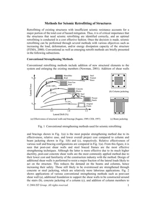
  • 1. Steel Framed Brace Precast Panels Concrete Blocks Steel Brace Monolithic Wall Post-Cast Wall 0.60-1.00Vw 0.62Vw 0.29Vw V0 Original Frame 0.5 1.0 1.5 Lateral Drift (%) Vw Lateral Force (a) Effectiveness of structural walls and bracings (Sugano, 1989; CEB, 1997) (c) Beam jacketing Fig. 1 Conventional strengthening methods used for seismic retrofitting © 2004 IST Group. All rights reserved. (b) Column jacketing 1 Methods for Seismic Retrofitting of Structures Retrofitting of existing structures with insufficient seismic resistance accounts for a major portion of the total cost of hazard mitigation. Thus, it is of critical importance that the structures that need seismic retrofitting are identified correctly, and an optimal retrofitting is conducted in a cost effective fashion. Once the decision is made, seismic retrofitting can be performed through several methods with various objectives such as increasing the load, deformation, and/or energy dissipation capacity of the structure (FEMA, 2000). Conventional as well as emerging retrofit methods are briefly presented in the following subsections. Conventional Strengthening Methods Conventional retrofitting methods include addition of new structural elements to the system and enlarging the existing members (Newman, 2001). Addition of shear walls and bracings shown in Fig. 1(a) is the most popular strengthening method due to its effectiveness, relative ease, and lower overall project cost compared to column and beam jacketing shown in Fig. 1(b) and (c), respectively. Relative effectiveness of various wall and bracing configurations are compared in Fig. 1(a). From this figure, it is seen that post-cast shear walls and steel braced frames are the most effective strengthening techniques. Although the latter is more effective due to its much higher ductility, post-cast concrete shear walls are the most commonly applied method due to their lower cost and familiarity of the construction industry with the method. Design of additional shear walls is performed to resist a major fraction of the lateral loads likely to act on the structure. This reduces the demand on the beams and columns, hence increasing their safety. Those still likely to be overstressed are strengthened through concrete or steel jacketing, which are relatively more laborious applications. Fig. 2 shows applications of various conventional strengthening methods such as post-cast shear wall (a), additional foundation to support the shear walls to be constructed around the stairs (b), concrete jacketing of a column (c), and addition of column members to
  • 2. remedy vertical irregularities (d). The main research need associated with conventional strengthening methods is optimization of the retrofit design to achieve a satisfactory structural performance level at a minimum cost based on reliably characterized seismic demand and structural capacity. (a) additional shear wall (b) additional foundations (c) jacketing (d) additional columns Fig. 2 Applications of conventional strengthening methods 7 6 5 4 3 2 1 © 2004 IST Group. All rights reserved. C2-WA1-UC1 2 Retrofit of Structures Using Innovative Materials Current research on advanced materials in civil engineering is mainly concentrated on high performance concrete and steel, and fiber reinforced plastic (FRP) composites. FRP composite materials have experienced a continuous increase of use in structural strengthening and repair applications around the world in the last fifteen years. High specific stiffness and specific weight combined with superior environmental durability of these materials have made them a competing alternative to the conventional strengthening methods. It was shown through experimental and analytical studies that externally bonded FRP composites can be applied to various structural members including columns, beams, slabs, and walls to improve their structural performance such as stiffness, load carrying capacity, and ductility (Büyüköztürk and Hearing, 1998). FRP composites have enjoyed varying degrees of success in different types of C2-UC1-WA1 0 0.005 0.01 0.015 0.02 0.025 0.03 0 Axial Strain Axial Stress (ksi) Plain concrete cylinder C1-W1 C2-W1-WA1 C1-WA1 C1-UC1 (a) failure modes (b) stress-strain curves of cylinders wrapped in various configurations Fig. 3 Performance and failure modes concrete cylinders wrapped with FRP composites in various fiber orientations
  • 3. applications. In general, applications that allow complete wrapping of the member with FRP have proven to be effective. Wrapping of columns to increase their load and deformation capacity is the most effective and most commonly used method of retrofitting with composites. However, certain performance and failure mode issues regarding different wrapping configuration and fiber orientations, shown in Fig. 3, still need to be well understood (Au, 2001). When wrapping is difficult or not allowed, such as when strengthening beams, slabs, or walls, success of the method is sometimes hindered by premature debonding failures (Günes, 2002). Fig. 4 shows the performance of beams strengthened using pultruded FRP plates in various configurations. It can be seen from this figure that flexural strengthening of beams without proper attention to brittle shear and debonding failure modes not only renders the strengthening application ineffective, but also harms the member by decreasing its ductility. This constitutes one of the main factors, along with their high material costs, hindering wide-range use of FRP materials (Büyüköztürk et al., 1999, Günes, 2002). Such problems can be reduced through proper design and anchorage of the external FRP reinforcement (Büyüköztürk et al., 2002a, 2002b, 2002c). Thus, decision makers must approach using these materials with caution and must ensure that the design is performed with adequate knowledge and skill, and verified through laboratory testing. Limited research and applications regarding seismic retrofitting of building systems with FRP composites have shown that composites retrofitting does not significantly alter the stiffness and dynamic properties of the building. The main benefit of retrofitting with composites is the increase in deformation capacity of the building, and in its load capacity to an extent. This may achieve the retrofit objectives for buildings with lightly insufficient seismic resistance. For buildings with large seismic deficiencies, a combination of conventional and FRP strengthening techniques may prove to be an effective retrofitting solution. Fig. 5 shows such an application where a historical school building in Istanbul was retrofitted using steel and FRP composites. The 3-D computer model of the building is shown in Fig. 5(a), the analysis of which revealed that under seismic design loads excessive cracking is expected around the openings in the exterior unreinforced concrete walls in the short direction due to stress concentrations as shown in Fig. 5(b). As a practical and economical solution, the retrofit 250 200 150 100 50 0 250 200 150 100 50 0 © 2004 IST Group. All rights reserved. 3 S1PF1M S1PF2C PP//22 D4@75 P/2 100 S3PS2M S3PS2C P/2 100 S4PS2M S4PS2C 0 5 10 15 20 Mid−span deflection (mm) Load, P (kN) 0 5 10 15 20 Mid−span deflection (mm) Load, P (kN) 250 200 150 100 50 0 0 5 10 15 20 Mid−span deflection (mm) Load, P (kN) (a) flexural (b) flexural + shear (c) flexural + shear + anchorage Fig. 4 Influence of shear strengthening and anchorage on FRP strengthened beam behavior under cyclic loading control beam (no strengthening)
  • 4. design involved replacement of the existing window frames with structural steel frames constructed from steel C-sections. A verification analysis of the retrofitted building showed that installation of steel window frames largely decreased the stress concentrations, but did not suffice to reduce all stresses to acceptable levels. For this reason, additional retrofitting was designed using externally bonded FRP composites around the openings in the walls to prevent or delay concrete crack propagation by bridging the stresses at crack locations. Thus, by combining conventional and innovative materials, an effective and economical retrofit design was achieved that did not significantly interfere with the function or historical and architectural character of the building. FRP composites are widely recognized for their potential use in seismic retrofitting applications. To achieve wide-range use of these materials, however, there is need for further research into a number of issues related to mechanics, design, and durability of FRP retrofitted concrete and steel systems. Despite considerable progress in these areas since early last decade (ACI-440F, 2000), further improvements are necessary to meet the needs of the retrofit industry. Failure mechanisms, with emphasis on brittle shear and debonding failures, must be thoroughly understood and associated design procedures must be incorporated in design codes. Influence of cyclic and fatigue loading on the FRP strengthened member performance must be characterized and accounted for in the design process. Although FRP composites are known for their favorable durability characteristics, only limited information is available on long-term durability and performance of FRP bonded concrete and steel systems. These issues need to be investigated through accelerated test studies and related design, application and protection requirements must be included in the design codes. © 2004 IST Group. All rights reserved. 4 Base Isolation The seismic base isolation technology involves placing flexible isolation systems between the foundation and the superstructure. By means of their flexibility and energy absorption capability, the isolation systems reflect and absorb part of the earthquake input energy before this energy is fully transmitted to the superstructure, reducing the energy dissipation demand on the superstructure. Base isolation causes the natural period of the structure to increase and results in increased displacements across the isolation level and reduced accelerations and displacements in the superstructure during an earthquake. This not only provides safety against collapse, but also largely reduces Concrete cracking MPa psi (a) 3-D building model (b) wall stresses (c) after installation of (d) additional FRP before retrofitting steel window frames retrofitting Fig. 5 A retrofit application combining conventional and composites retrofitting
  • 5. damage, which is crucial for facilities that should remain operational after severe earthquakes such as emergency response centers, hospitals, and fire stations (EERI, 1990; ATC, 1993; Kelly, 1993; Skinner et al., 1993; Connor and Klink, 1996; Komodromos, 2001). Base isolation can also be used in seismic retrofitting of historic structures without impairing their architectural characteristics by reducing the induced seismic forces. Fig. 6 shows the results of a feasibility study for base isolation of a historical school building in Istanbul (Bachas et al., 2001). The structural system of the building is formed by thick exterior unreinforced concrete walls resisting lateral loads and interior steel frames carrying the vertical loads. A combination of lead-plug rubber bearings and natural rubber bearings were considered for the exterior walls and the interior frames, respectively. The basic design philosophy shown in (a) is to increase the fundamental period of the structure so that the effective seismic demand on the structure is less than that can safely be resisted by the structure. Analysis results showing the deformed shape of the building before and after the base isolation in (b) and (c), respectively, make it clear that base isolation reduces the deformations and hence the stresses in the building. Base isolation is generally suitable for low to medium rise buildings, usually up to 10- 12 stories high, which have their fundamental frequencies in the range of expected dominant frequencies of earthquakes. Superstructure characteristics such as height, width, aspect ratio, and stiffness are important in determining the applicability and effectiveness of seismic isolation. The seismicity of the region and the underlying soil conditions should also be considered in the feasibility studies and design process. Base isolation should be avoided in areas where expected fundamental frequencies of the earthquakes are in the lower frequency domain or on soft soil sites where amplification of low earthquake frequencies may occur. One other constraint in the application of base isolation is the large relative displacements between the superstructure and the supporting ground at the isolation level. A clearance around the building must be provided and maintained through the life of the structure to accommodate the expected large displacements. Such displacements may be reduced with the incorporation of additional stiffness and energy dissipation mechanisms in the isolation system. The International Building Code (IBC, 2000) and FEMA 356 (FEMA, 2000) specify the methodologies according to which seismically isolated structures can be designed. Both the isolation system and the isolated structure are required to be designed to resist the deformation and stresses produced by seismic events. Two levels of earthquake input are considered in design. The design earthquake (475-year return period) is used to calculate the total design displacement of the isolation system and the lateral forces and displacements of the isolated structure, and the maximum considered earthquake (1000- year return period) is used to calculate the total maximum displacement of the isolation system to ensure its integrity even at extreme ground shaking. Deformation characteristics of the isolation system is required to be based on properly substantiated prototype tests with predefined sequence and number of loading cycles. © 2004 IST Group. All rights reserved. 5
  • 6. T Sa Safety limit Fixed base T1 T3 Base isolated T2 (a) Design of base isolation (b) Deformations before base isolation (c) After base isolation Fig. 6 Analysis and design of building base isolation Seismic isolation is proven to be a very effective method for protecting buildings and other structures against seismic hazards (Skinner et al., 1993; Kitagawa and Midorikawa, 1998; Komodromos, 2001). An important disadvantage of the method, however, is that it cannot be applied partially to structures, unlike most other seismic retrofitting methods. For this reason, the cost of base isolation is often significantly higher than alternative retrofitting methods. This often limits the application of base isolation to (1) special buildings, such as certain industrial, research, public and hospital buildings that contain sensitive equipment or strict operational and performance requirements, (2) historical buildings, the architectural and historic character of which may be harmed by alternative retrofitting methods, (3) bridges, for which relatively less number of isolators are required and installation is easier. In order to increase the cost competitiveness of base isolation for buildings, there is need for research in the areas of reducing the application costs through efficient design and specialized equipment, and optimization of isolator types, combination, and arrangement. © 2004 IST Group. All rights reserved. 6 Supplemental Energy Dissipation and Structural Control An alternative and often more cost efficient retrofitting strategy compared to base isolation is installation of supplemental energy dissipation devices in structures as a means for passive or active structural control (Housner et al., 1997; EERI, 1993; Constantinou and Symans, 1993; Symans and Constantinou, 1999; Soong, 1990; Soong and Dargush, 1997, FEMA, 2000). The objective of structural control is to reduce structural vibrations for improved safety and/or serviceability under wind and earthquake loadings. Passive control systems reduce structural vibration and associated forces through energy dissipation devices that do not require external power. These devices utilize the motion of the structure to develop counteracting control forces and absorb a portion of the input seismic energy. Active control systems, however, enhance structural response through control forces developed by force delivery devices that rely on external power to operate. The actuator forces are controlled by real time controllers that process the information obtained from sensors within the structure. Semi-active control systems combine passive and active control devices and are sometimes used to optimize the structural performance with minimal external power requirements. Fig. 7 shows the basic principles of various control systems commonly used to control wind and seismic forces acting on building structures. The severity of seismic demand on a structure is proportional to its stiffness and inversely proportional to its damping or energy dissipation capacity. Thus, installing
  • 7. supplemental energy dissipating devices in the structure reduces the seismic demand and results in increased safety of the structure and its contents from the damaging effects of earthquakes. In recent years, considerable attention has been paid to research and development of structural control devices, with particular emphasis on improving wind and seismic response of buildings and bridges. In both areas, efforts have been made to develop the structural control concept into a workable technology, and as a result, such devices have been installed in a variety of structures around the world. The most challenging aspect of vibration control research in civil engineering is the fact that this is a field that requires integration of a number of diverse disciplines, some of which are not within the domain of traditional civil engineering. These include computer science, data processing, control theory, material science, sensing technology, as well as stochastic processes, structural dynamics, and wind and earthquake engineering. These coordinated efforts have facilitated collaborative research among researchers from a diverse background and have accelerated the research to the implementation process. Continued research is essential in this area to develop effective and affordable retrofitting solutions for structures with insufficient seismic resistance. A special concern regarding the use of energy dissipation devices in structures with high characteristic variability is the fact that the effectiveness of such devices is dependent on the deformation capacity of the structure. For structures that suffer from inadequate seismic detailing, which translates into insufficient deformation capacity, great caution must be exercised in use of these devices for seismic retrofitting. A feasible solution may be to combine this technique with deformation enhancement measures to ensure their effectiveness. This constitutes an important research area with valuable potential contribution and high potential benefits. © 2004 IST Group. All rights reserved. 7 Effects of Seismic Retrofitting on Structural Performance The seismic retrofit techniques briefly presented in the preceding sections vary in the mechanisms that they decrease the seismic risk of structures (ATC, 1996). Fig. 8 graphically illustrates these mechanisms by means of their effects on the seismic demand and structural capacity curves shown in Part 2. These effects are presented in the following paragraphs at a simplified conceptual level. The typical effect of conventional strengthening methods is shown in Fig. 8(a). Conventional strengthening applications generally lead to an increase in both the stiffness and the lateral load capacity of the structure. This is shown by the capacity curve of the strengthened structure, Cs, which has a higher slope and peak compared to the capacity curve before strengthening, Cu. Due to the increased stiffness, which translates into a decreased fundamental period, the seismic demand on the structure is also increased, as shown by the demand curve for the strengthened structure, Ds, compared to that for the unstrengthened structure, Du. Although the capacity increase is partly alleviated by the increase in seismic demand, the overall performance of the structure is improved as shown by the locations of the performance points on the spectral displacement axis for before and after strengthening.
  • 8. Increasing the overall deformation capacity of a structure is also an effective seismic retrofitting method. Insufficient deformation capacity of structural members is usually caused by their inadequate seismic detailing. Ductility of these members can be increased through various measures such as providing additional confinement by additional stirrups or wrapping with FRP composites. Fig. 8(b) shows the effect of deformation or ductility enhancement on the structural performance. While the capacity curve of the structure prior to retrofitting does not intersect the demand curve, an intersection i.e. a performance point is obtained after retrofitting. It is important to note that since the stiffness and damping characteristics of the structure are not significantly altered, the demand curve remains essentially the same after retrofitting. Chevron brace with viscous dampers Tuned liquid column damper Tuned liquid damper Diagonal brace with viscous or viscoelastic damper © 2004 IST Group. All rights reserved. 8 Pall friction damper Tuned mass damper Active mass damper Chevron brace with viscoelastic damper Hybrid mass damper damper spring actuator Fig. 7 Supplemental energy dissipation devices
  • 9. Du (a) Effect of structural strengthening (b) Effect of deformation enhancement The effectiveness of seismic base isolation in increasing the structural performance during seismic events is shown in Fig. 8(c). Base isolation significantly increases the effective fundamental period and deformation capacity of the structure. This is apparent from the capacity curve of the base isolated structure, Cs, shown in Fig. 8(c). It seems somewhat contradictory, however, that the demand curve for the base isolated structure, Ds, is shown as higher than the fixed-base condition, Du, since base isolation is known to decrease the seismic demand on the structure. This is due to the fact that the energy dissipation in a base isolated structure is significantly different than the same structure in fixed-base condition. Due to relatively lower stiffness of the isolation system, the effective damping for a certain spectral displacement is lower in the base isolated structure, resulting in a higher apparent seismic demand. However, since the deformation capacity of the structure is significantly increased, a major portion of which takes place at the isolation level, the building can safely tolerate this apparent increase in the seismic demand, resulting in a satisfactory performance level. Seismic retrofitting of structures using energy dissipation devices such as those shown in Fig. 7 result in an increase in the stiffness, load capacity, and effective damping of the structures. Effects of these on the structural performance is shown in Fig. 8(d). As can be seen from the figure, the effect of energy dissipation devices on the capacity curve is similar to structural strengthening with conventional methods shown in Fig. 8(a). Additional advantage of using energy dissipation devices is that the seismic demand on the structure is also reduced due to increase in the effective damping of the structure. Comparing the seismic demand curves before (Du) and after (Ds) retrofitting in Fig. 8(a) © 2004 IST Group. All rights reserved. 9 Ds= Demand curve for strengthened structure Du= Demand curve for unstrengthened structure Cs= Capacity curve for strengthened structure Cu= Capacity curve for unstrengthened structure Spectral Displacement Spectral Acceleration Performance Point of Strengthened Structure Performance Point of Original Structure Ds Du Cs Cu Spectral Acceleration Performance Point of Strengthened Structure Spectral Displacement Ds , Du Cs Cu Isolator Displacement Spectral Acceleration Performance Point of Strengthened Structure Spectral Displacement Ds Cs Cu Spectral Acceleration Performance Point of Strengthened Structure Performance Point of Original Structure Spectral Displacement Cs Cu Du Ds (c) Effect of base isolation (d) Effect of enhanced energy dissipation Fig. 8 Effects of various retrofit measures on structural performance
  • 10. and (d), it is apparent that use of energy dissipation devices results in a more desired performance level compared to conventional strengthening methods. Selection of a particular retrofitting technique depends on the seismic demand, structural capacity, the required performance level, functional characteristics and the importance of the structure. The main challenge is to achieve a desired performance level at a minimum cost, which can best be achieved through a detailed nonlinear analysis as demonstrated by Part 2 and the above discussions. Ideally, each structure must be evaluated in detail to determine the optimum retrofit strategy compatible with its characteristic. In the case of large building stocks, however, a classification of structures according to their current and required performance levels may lead to development of common standardized retrofit strategies for structures in the same group, which in turn may prove to be a more rapid and cost effective overall methodology. © 2004 IST Group. All rights reserved. 10