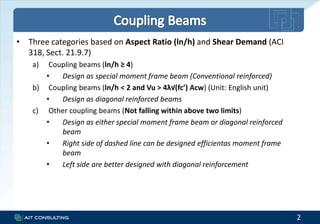
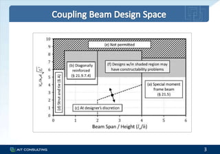
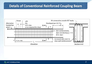
5 November 2015
• Three categories based on Aspect Ratio (ln/h) and Shear Demand (ACI
318, Sect. 21.9.7)
a) Coupling beams (ln/h ≥ 4)
• Design as special moment frame beam (Conventional reinforced)
b) Coupling beams (ln/h < 2 and Vu > 4λ√(fc’) Acw) (Unit: English unit)
• Design as diagonal reinforced beams
c) Other coupling beams (Not falling within above two limits)
• Design as either special moment frame beam or diagonal reinforced
beam
• Right side of dashed line can be designed efficientas moment frame
beam
• Left side are better designed with diagonal reinforcement
2
3
• Flexure Design
– Design as special moment frame beams (ACI 318, Sect. 21.5)
– Reinforcement placed horizontally at top and bottom
• Shear Design
– Shear design is based on probable moment strength (use 1.25 fy)
– Within 2h of member ends, shear strength is calculated based on steel
only
• Confinement
– Hoops confine at end regions
– If ln/h is relatively small, longitudinal cannot be lapped
– Easier to use closed hoops over entire beam rather than only 2h at
each end
5
• Development Length in Tension (ACI 318, Sect. 21.7.5)
– For standard 90 deg. Hook, located within confined core
• ldh = fy db / (65 √fc’), not less than 8 db, 6 in.
– For straight bar
• ld = 2.5 x ldh for 90 deg. Hook, if depth of concrete cast in one lift
beneath the bar does not exceed 12 in.
• ld = 3.5 x ldh for 90 deg. Hook, if depth of concrete cast in one lift
beneath the bar exceeds 12 in.
• Straight bars terminated at a joint shall pass through confined core.
• Any portion of ld not within the confined core shall be increased by a
factor of 1.6.
6
7
• Shear Design
Tu = Cu = Ф As fy
Vu = 2 Tu sinα = 2ФAsfy sinα
Vn = 2Avdfy sinα ≤ 10√fc’ Acw (ACI 318, Eq. 21-9)
– Minimum four bars in each group of diagonal
• Confinement (2 Options)
a) Confine individual diagonals
b) Confine entire beam cross section
9
10
11
Confinement of Individual Diagonals
– Diagonal bars shall be enclosed by transverse reinforcement out-to-out
dimensions not smaller than bw/2 in the direction parallel to bw and
bw/5 along the other sides
– Volumetric ratio of confinement,
ρs = max (0.12 fc’ / fyt , 0.45 (Ag/Ach – 1) fc’ / fyt)
– Max. spacing = min (s0, 6db)
– s0 = 4 + (14 – hx) / 3
12
Confinement of Entire Beam Section
– Volumetric ratio of confinement,
ρs = max (0.12 fc’ / fyt , 0.45 (Ag/Ach – 1) fc’ / fyt)
– Max. spacing = min (6 in., 6db)
• Development Length
– Design for 1.25 fy in tension
• Regardless of the confinement option selected, longitudinal and transverse
reinforcement shall be distributed around the beam perimeter with total
area in each direction not less than 0.002 bw s with min. spacing of 12 in.
• Typically No. 4 or 5 bars should extend only a short distance into the wall
boundary not to develop significant tensile stress due to beam flexure
13
14
0
10
20
30
40
50
60
70
80
-0.01 0 0.01 0.02 0.03 0.04
Story
Coupling Beam Rotation
Coupling Beam Shear Hinge Rotation at V1
LOM_STG
TAB
UNI
KOC
DUZ
STL
LOM_LGP
Average
15
Coupling Beam Reinforcement Details

AITC Coupling Beam Design Procedure (20151106)

  • 1.
  • 2.
    • Three categoriesbased on Aspect Ratio (ln/h) and Shear Demand (ACI 318, Sect. 21.9.7) a) Coupling beams (ln/h ≥ 4) • Design as special moment frame beam (Conventional reinforced) b) Coupling beams (ln/h < 2 and Vu > 4λ√(fc’) Acw) (Unit: English unit) • Design as diagonal reinforced beams c) Other coupling beams (Not falling within above two limits) • Design as either special moment frame beam or diagonal reinforced beam • Right side of dashed line can be designed efficientas moment frame beam • Left side are better designed with diagonal reinforcement 2
  • 3.
  • 5.
    • Flexure Design –Design as special moment frame beams (ACI 318, Sect. 21.5) – Reinforcement placed horizontally at top and bottom • Shear Design – Shear design is based on probable moment strength (use 1.25 fy) – Within 2h of member ends, shear strength is calculated based on steel only • Confinement – Hoops confine at end regions – If ln/h is relatively small, longitudinal cannot be lapped – Easier to use closed hoops over entire beam rather than only 2h at each end 5
  • 6.
    • Development Lengthin Tension (ACI 318, Sect. 21.7.5) – For standard 90 deg. Hook, located within confined core • ldh = fy db / (65 √fc’), not less than 8 db, 6 in. – For straight bar • ld = 2.5 x ldh for 90 deg. Hook, if depth of concrete cast in one lift beneath the bar does not exceed 12 in. • ld = 3.5 x ldh for 90 deg. Hook, if depth of concrete cast in one lift beneath the bar exceeds 12 in. • Straight bars terminated at a joint shall pass through confined core. • Any portion of ld not within the confined core shall be increased by a factor of 1.6. 6
  • 7.
  • 9.
    • Shear Design Tu= Cu = Ф As fy Vu = 2 Tu sinα = 2ФAsfy sinα Vn = 2Avdfy sinα ≤ 10√fc’ Acw (ACI 318, Eq. 21-9) – Minimum four bars in each group of diagonal • Confinement (2 Options) a) Confine individual diagonals b) Confine entire beam cross section 9
  • 10.
  • 11.
  • 12.
    Confinement of IndividualDiagonals – Diagonal bars shall be enclosed by transverse reinforcement out-to-out dimensions not smaller than bw/2 in the direction parallel to bw and bw/5 along the other sides – Volumetric ratio of confinement, ρs = max (0.12 fc’ / fyt , 0.45 (Ag/Ach – 1) fc’ / fyt) – Max. spacing = min (s0, 6db) – s0 = 4 + (14 – hx) / 3 12
  • 13.
    Confinement of EntireBeam Section – Volumetric ratio of confinement, ρs = max (0.12 fc’ / fyt , 0.45 (Ag/Ach – 1) fc’ / fyt) – Max. spacing = min (6 in., 6db) • Development Length – Design for 1.25 fy in tension • Regardless of the confinement option selected, longitudinal and transverse reinforcement shall be distributed around the beam perimeter with total area in each direction not less than 0.002 bw s with min. spacing of 12 in. • Typically No. 4 or 5 bars should extend only a short distance into the wall boundary not to develop significant tensile stress due to beam flexure 13
  • 14.
    14 0 10 20 30 40 50 60 70 80 -0.01 0 0.010.02 0.03 0.04 Story Coupling Beam Rotation Coupling Beam Shear Hinge Rotation at V1 LOM_STG TAB UNI KOC DUZ STL LOM_LGP Average
  • 15.