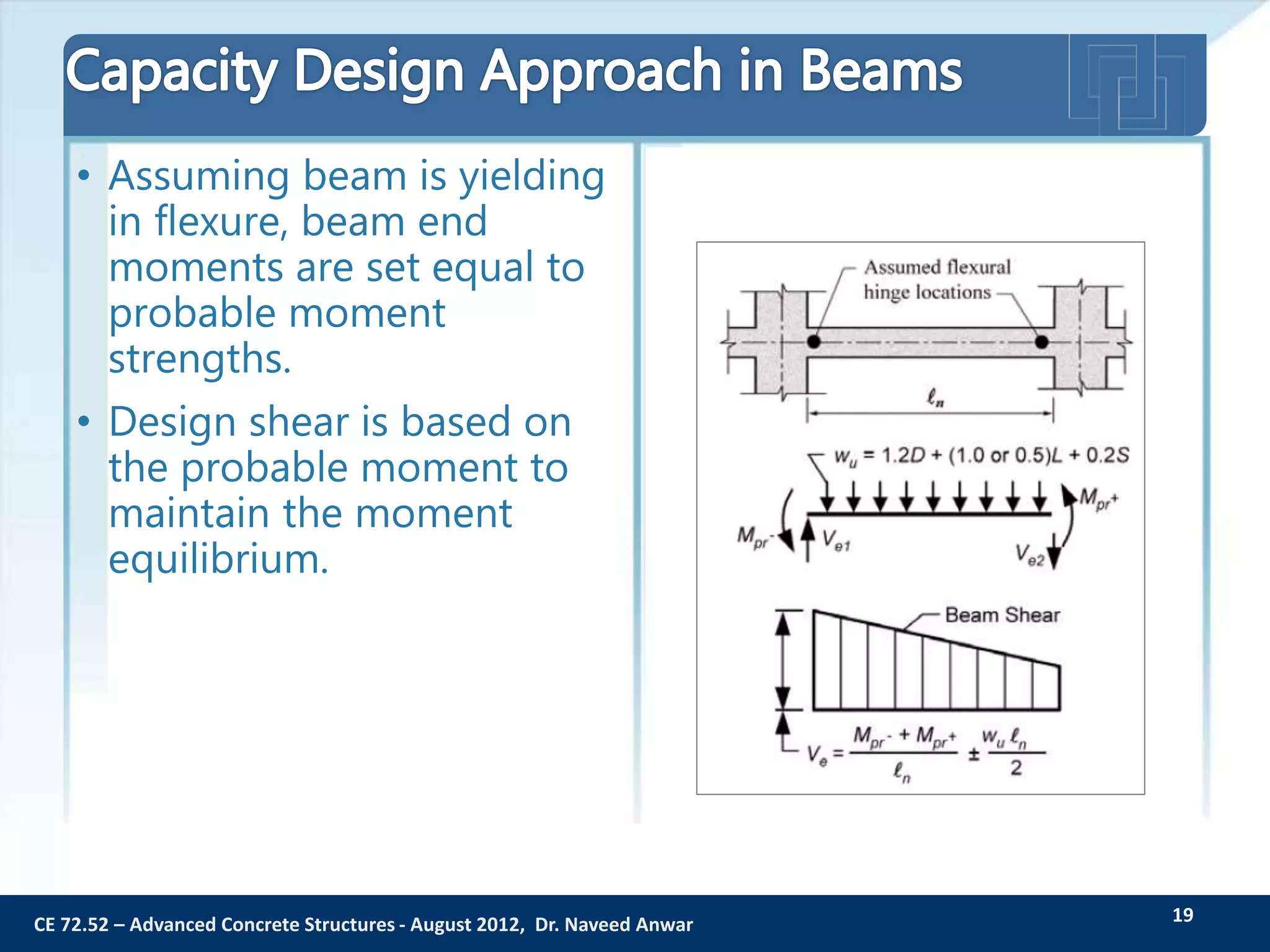
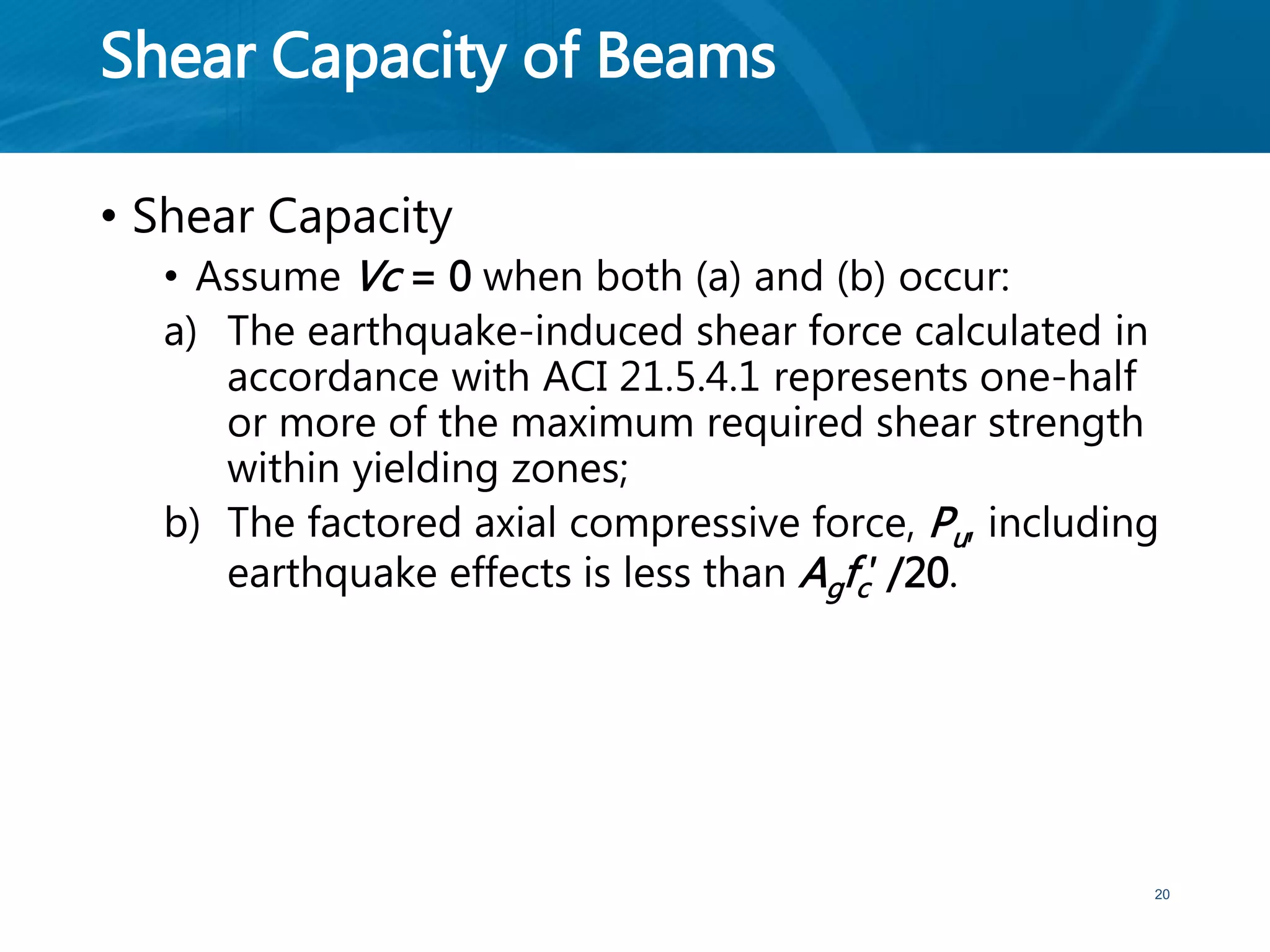
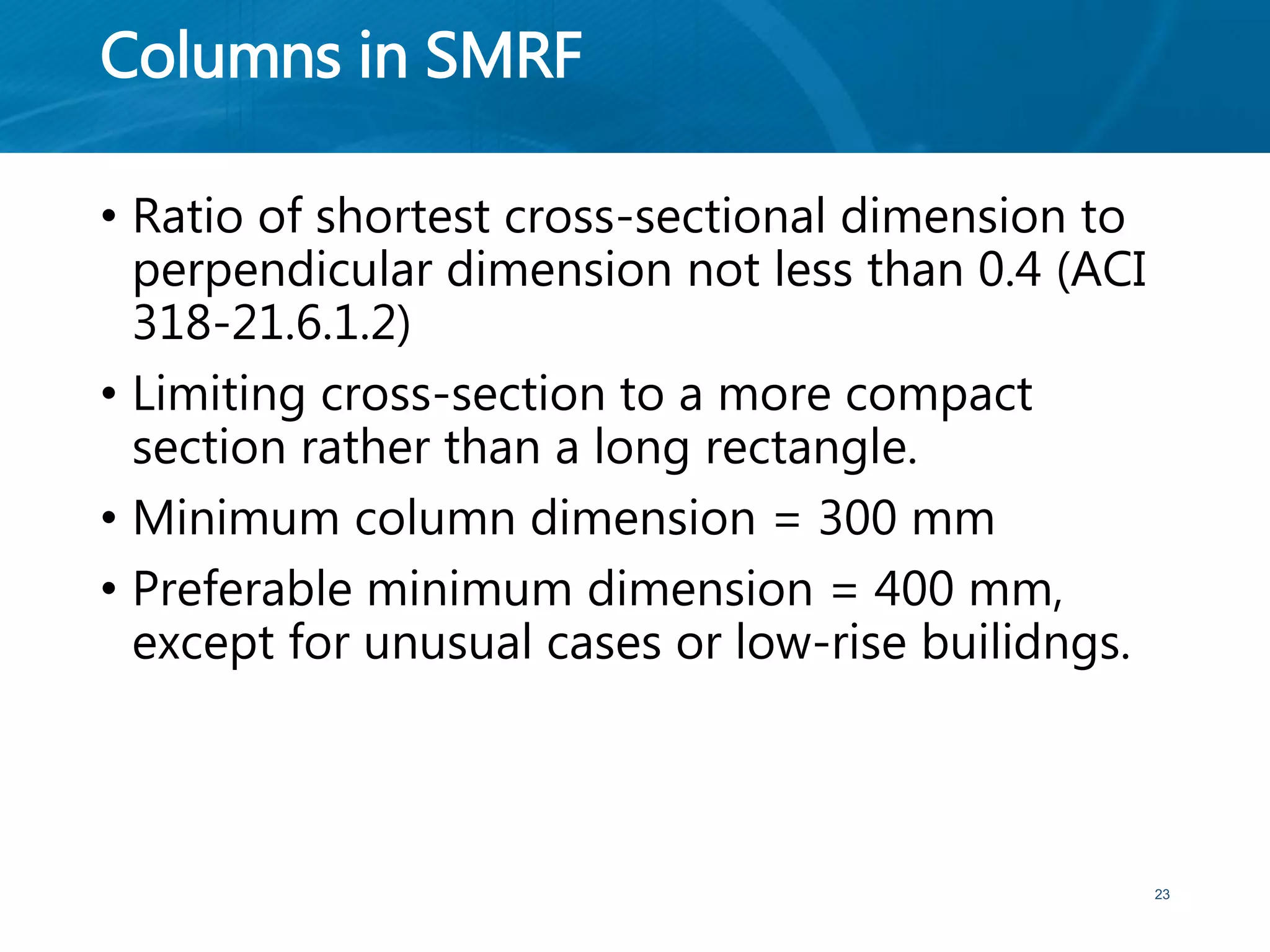
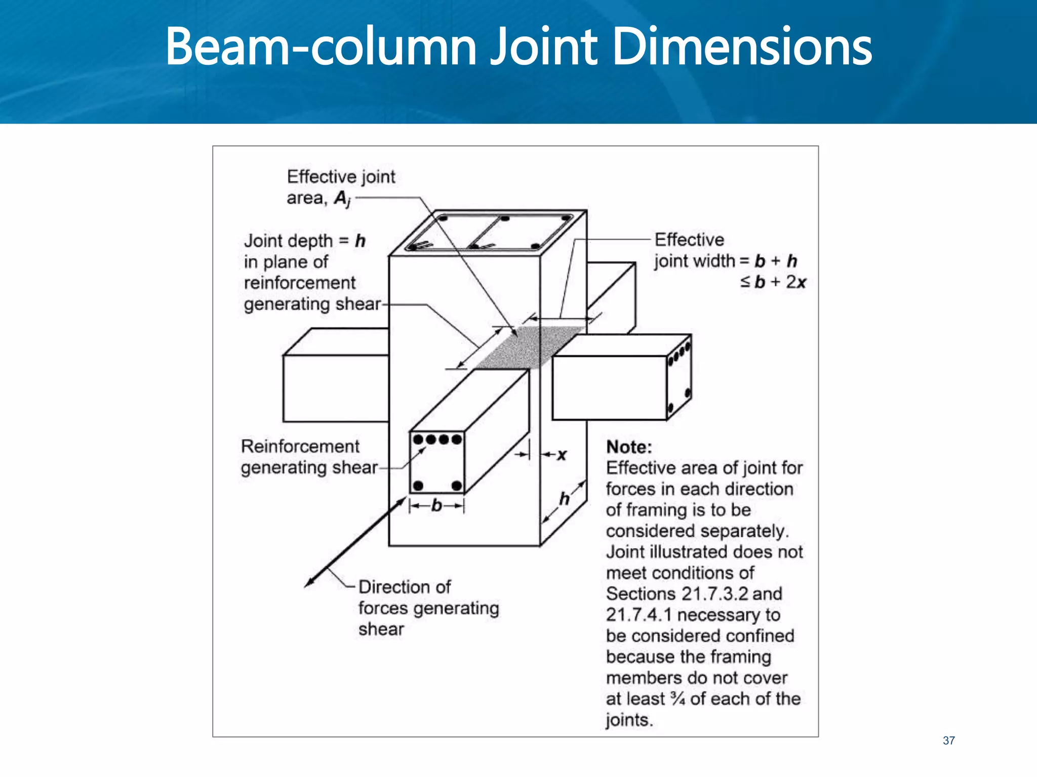
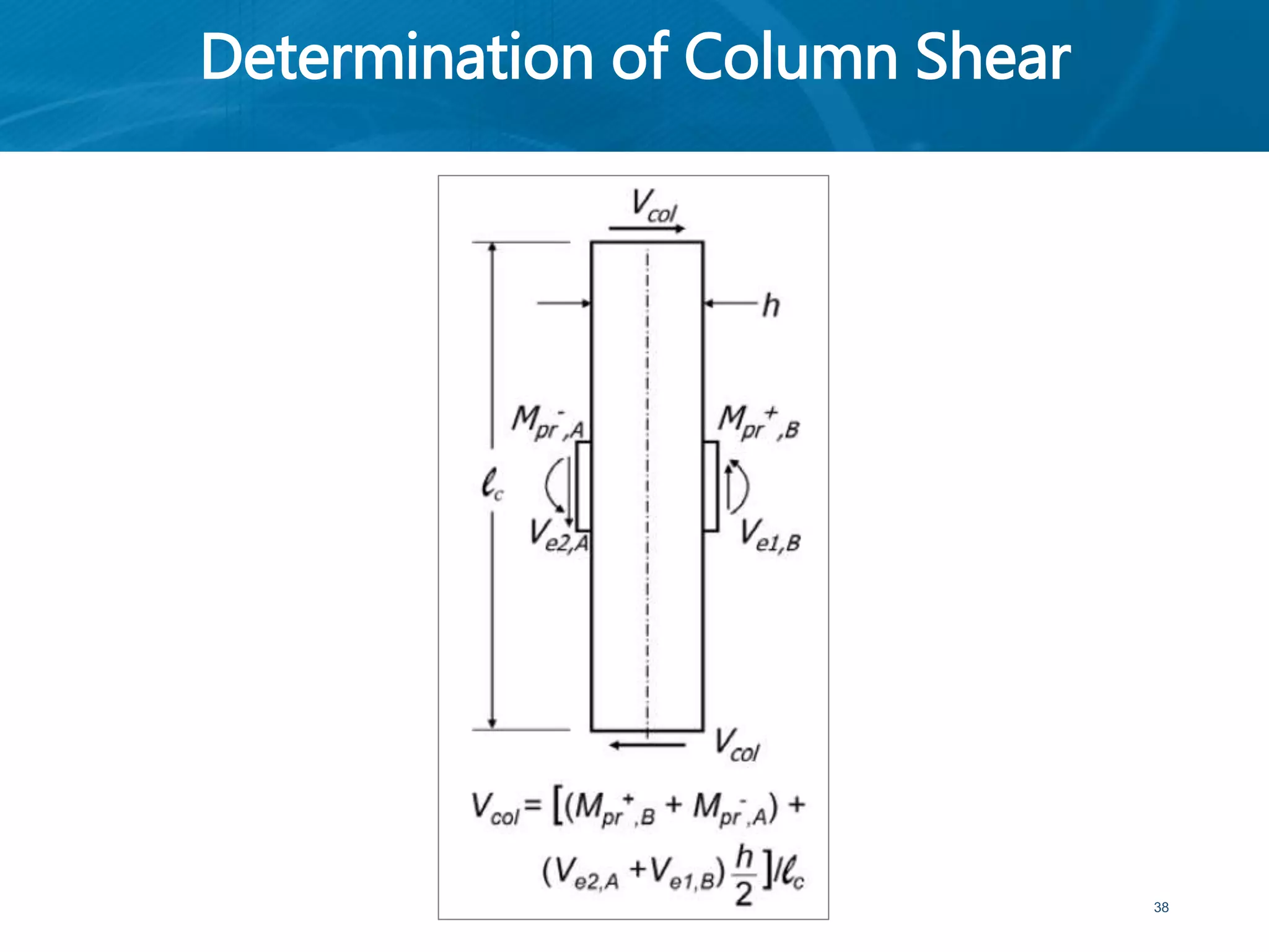
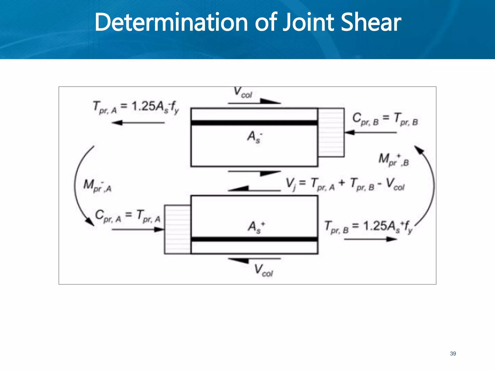
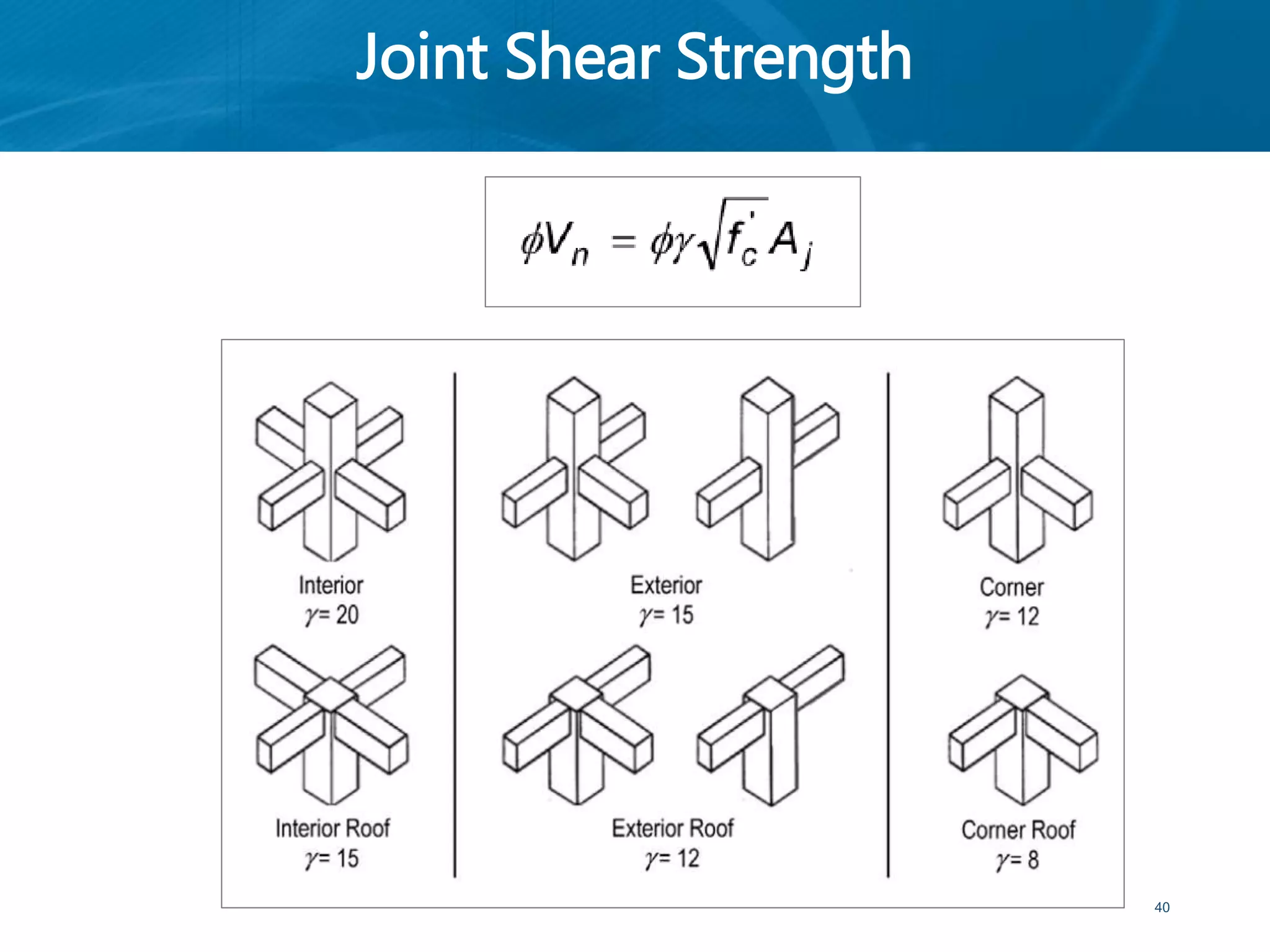
1
CE 72.52 Advanced Concrete
Lecture 4a:
Member
Behavior
(Beams and Columns)
Naveed Anwar
Executive Director, AIT Consulting
Director, ACECOMS
Affiliate Faculty, Structural Engineering, AIT
August - 2015
Seismic Design
2
Source: FEMA P695 / June 2009
Moment Resisting Frame
• Ordinary moment resisting frame (OMRF)
• Intermediate moment resisting frame (IMRF)
• Special moment resisting frame (SMRF)
3
Special Moment Resisting
Frame
4
Principles for Design of SMRF
• Proportioning and detailing requirements are
intended to ensure that inelastic response is
ductile.
• Three main goals
1) To achieve a strong-column/weak-beam design
that spreads inelastic response over several stories
2) To avoid shear failure
3) To provide details that enable ductile flexural
response in yielding regions
5
Design a Strong-column / Weak-beam
Frame
• If the building has weak columns, drift tends to
concentrate in one or a few stories, and may
exceed the drift capacity of the columns. If
columns provide a stiff and strong spine over the
building height, drift will be more uniformly
distributed and localized damage will be reduced.
• Additionally, it is important to recognize that the
columns in a given story support the weight of the
entire building above those columns, whereas the
beams only support the gravity loads of the floor
of which they form a part; therefore, failure of a
column is of greater consequence than failure of a
beam.
6
Design a Strong-column / Weak-beam
Frame
• ACI 318 adopts the strong-column/weak-beam
principle by requiring that the sum of column
strengths exceed the sum of beam strengths at
each beam-column connection of a special
moment frame. Studies have shown that the full
structural mechanism can only be achieved if the
column-to-beam strength ratio is relatively large
(on the order of four).
• As this is impractical in most cases, a lower
strength ratio of 1.2 is adopted by ACI 318. Some
column yielding associated with an intermediate
mechanism is to be expected, and columns must
be detailed accordingly.
7
Strong-Column/Weak Beam Frame
8
Strong-Column/Weak Beam Frame Requirement for SMRF
Source: NEHRP Seismic Design Technical Brief No. 1
Strong-Column/Weak Beam Frame
9
Avoid Shear Failure
• Ductile response requires that members yield in
flexure, and that shear failure be avoided. Shear
failure is avoided through use of a capacity-
design approach. The general approach is to
identify flexural yielding regions, design those
regions for code-required moment strengths,
and then calculate design shears based on
equilibrium assuming the flexural yielding
regions develop probable moment strengths.
10
Avoid Shear Failure
• Probable moment strength is calculated from
conventional flexural theory considering the as-
designed cross section, using φ = 1.0, and
assuming reinforcement yield strength equal to
at least 1.25 fy.
11
Detail for Ductile Behavior
• Plain concrete has relatively small usable
compressive strain capacity (around 0.003), and
this might limit the deformability of beams and
columns of special moment frames.
• Strain capacity can be increased ten-fold by
confining the concrete with reinforcing spirals or
closed hoops.
• The hoops act to restrain dilation of the core
concrete as it is loaded in compression, and this
confining action leads to increased strength and
strain capacity.
• Hoops typically are provided at the ends of
columns, as well as through beam-column joints,
and at the ends of beams.
12
Beams in SMRF
13
Beams in SMRF
• Typical economical beam span, 6 to 9 m
• Resulting beam depth that will support typical
gravity loads and requisite seismic forces
without overloading adjacent beam-column
joints and columns.
• Clear span > 4 x effective depth (ACI 21.5.1.2)
• Beams are allowed to be wider than supporting
columns, but beam width normally does not
exceed column width.
14
Beams in SMRF
15
Ref: ACI 318-08 Fig. R21.5.1
Beams in SMRF
• Divided into three different zones when
considering where hoops and stirrups can be
placed:
• At each end of the beam (2h) where flexural
yielding is expected to occur
• Needs to be well confined because this is where the
beam is expected to undergo flexural yielding and
this is the location with the highest shear.
Therefore, closely spaced, closed hoops are
required in this zone
• the zone along lap-spliced bars, if any;
• the remaining length of the beam
16
Beams in SMRF
17
Hoops and Stirrups Locations and Spacing Requirements
Beams in SMRF
18
Hoop Reinforcement Details
CE 72.52 – Advanced Concrete Structures - August 2012, Dr. Naveed AnwarCE 72.52 – Advanced Concrete Structures - August 2012, Dr. Naveed Anwar
• Assuming beam is yielding
in flexure, beam end
moments are set equal to
probable moment
strengths.
• Design shear is based on
the probable moment to
maintain the moment
equilibrium.
19
Shear Capacity of Beams
• Shear Capacity
• Assume Vc = 0 when both (a) and (b) occur:
a) The earthquake-induced shear force calculated in
accordance with ACI 21.5.4.1 represents one-half
or more of the maximum required shear strength
within yielding zones;
b) The factored axial compressive force, Pu, including
earthquake effects is less than Agfc′ /20.
20
Shear Capacity of Beams
• Experimental studies of reinforced concrete
members subjected to cyclic loading have
demonstrated that more shear reinforcement is
required to ensure a flexural failure if the member
is subjected to alternating nonlinear displacements
than if the member is loaded in only one direction:
the necessary increase of shear reinforcement
being higher in the case of no axial load. The
added conservatism on shear is deemed necessary
in locations where potential flexural hinging may
occur.
• However, this stratagem, chosen for its relative
simplicity, should not be interpreted to mean that
no concrete is required to resist shear.
21
Columns in SMRF
22
Columns in SMRF
• Ratio of shortest cross-sectional dimension to
perpendicular dimension not less than 0.4 (ACI
318-21.6.1.2)
• Limiting cross-section to a more compact
section rather than a long rectangle.
• Minimum column dimension = 300 mm
• Preferable minimum dimension = 400 mm,
except for unusual cases or low-rise builidngs.
23
Columns in SMRF
• First approximation, the columns can be
designed for the maximum factored gravity
loads while limiting the area of reinforcement
to between 1 % and 3 %.
• ACI 318 allows the longitudinal reinforcement
to reach 6 % of the gross section area, but this
amount of reinforcement results in very
congested splice locations.
24
Nominal Flexural Strength of Strong-
column/Weak-beam
25
Strong-column / Weak-beam Requirements
• In some cases it may not be practical to satisfy
the strong-column/ weak-beam provisions for
a small number of columns.
• The strength and stiffness of such columns
cannot be considered as part of the special
moment frame.
• These columns must also satisfy the
requirements of ACI 318 - 21.13, that is,
columns not designated as part of the seismic
force-resisting system.
26
Transverse Reinforcement
• The column transverse reinforcement should initially be
selected based on the confinement requirements of
ACI 318 - 21.6.4.
• For rectangular cross sections, the total cross-sectional
area of rectangular hoop reinforcement is not to be
less than that required by either of the following two
equations, whichever gives the larger amount.
27
Transverse Reinforcement
28
Column Design Shear
• The column design shear is defined as the larger of the
shear from procedure a and the shear from either
procedure b or procedure c.
29
Probable Moment for Column
30
Shear Capacity of Columns
• Assuming Vc = 0 when both (a) and (b) occur:
a) The earthquake-induced shear force, calculated in
accordance with 21.6.5.1, represents one-half or
more of the maximum required shear strength
within lo;
b) The factored axial compressive force, Pu, including
earthquake effects is less than Agfc′ /20.
31
Shear Capacity of Columns
• Length lo shall not be less than the largest of
(a), (b),and (c):
a) The depth of the member at the joint face or at
the section where flexural yielding is likely to
occur
b) One-sixth of the clear span of the member;
c) 450 mm.
32
Column Transverse Reinforcement Spacing
Requirements
33
Beam-column Joints in
SMRF
34
Beam-column Joints
• The frame yielding mechanism determines the
forces acting on the column and beam-column
joint.
35
Beam-column Joint Dimensions
• Aj is the effective cross-sectional area within a
joint computed from joint depth times effective
joint width. Joint depth shall be the overall
depth of the column, h. Effective joint width
shall be the overall width of the column, except
where a beam frames into a wider column,
effective joint width shall not exceed the
smaller of (a) and (b):
a) Beam width plus joint depth
b) Twice the smaller perpendicular distance from
longitudinal axis of beam to column side.
36
Beam-column Joint Dimensions
37
Determination of Column Shear
38
Determination of Joint Shear
39
Joint Shear Strength
40
41

CE 72.52 - Lecture6 - Member Behavior

  • 1.
    1 CE 72.52 AdvancedConcrete Lecture 4a: Member Behavior (Beams and Columns) Naveed Anwar Executive Director, AIT Consulting Director, ACECOMS Affiliate Faculty, Structural Engineering, AIT August - 2015
  • 2.
  • 3.
    Moment Resisting Frame •Ordinary moment resisting frame (OMRF) • Intermediate moment resisting frame (IMRF) • Special moment resisting frame (SMRF) 3
  • 4.
  • 5.
    Principles for Designof SMRF • Proportioning and detailing requirements are intended to ensure that inelastic response is ductile. • Three main goals 1) To achieve a strong-column/weak-beam design that spreads inelastic response over several stories 2) To avoid shear failure 3) To provide details that enable ductile flexural response in yielding regions 5
  • 6.
    Design a Strong-column/ Weak-beam Frame • If the building has weak columns, drift tends to concentrate in one or a few stories, and may exceed the drift capacity of the columns. If columns provide a stiff and strong spine over the building height, drift will be more uniformly distributed and localized damage will be reduced. • Additionally, it is important to recognize that the columns in a given story support the weight of the entire building above those columns, whereas the beams only support the gravity loads of the floor of which they form a part; therefore, failure of a column is of greater consequence than failure of a beam. 6
  • 7.
    Design a Strong-column/ Weak-beam Frame • ACI 318 adopts the strong-column/weak-beam principle by requiring that the sum of column strengths exceed the sum of beam strengths at each beam-column connection of a special moment frame. Studies have shown that the full structural mechanism can only be achieved if the column-to-beam strength ratio is relatively large (on the order of four). • As this is impractical in most cases, a lower strength ratio of 1.2 is adopted by ACI 318. Some column yielding associated with an intermediate mechanism is to be expected, and columns must be detailed accordingly. 7
  • 8.
    Strong-Column/Weak Beam Frame 8 Strong-Column/WeakBeam Frame Requirement for SMRF Source: NEHRP Seismic Design Technical Brief No. 1
  • 9.
  • 10.
    Avoid Shear Failure •Ductile response requires that members yield in flexure, and that shear failure be avoided. Shear failure is avoided through use of a capacity- design approach. The general approach is to identify flexural yielding regions, design those regions for code-required moment strengths, and then calculate design shears based on equilibrium assuming the flexural yielding regions develop probable moment strengths. 10
  • 11.
    Avoid Shear Failure •Probable moment strength is calculated from conventional flexural theory considering the as- designed cross section, using φ = 1.0, and assuming reinforcement yield strength equal to at least 1.25 fy. 11
  • 12.
    Detail for DuctileBehavior • Plain concrete has relatively small usable compressive strain capacity (around 0.003), and this might limit the deformability of beams and columns of special moment frames. • Strain capacity can be increased ten-fold by confining the concrete with reinforcing spirals or closed hoops. • The hoops act to restrain dilation of the core concrete as it is loaded in compression, and this confining action leads to increased strength and strain capacity. • Hoops typically are provided at the ends of columns, as well as through beam-column joints, and at the ends of beams. 12
  • 13.
  • 14.
    Beams in SMRF •Typical economical beam span, 6 to 9 m • Resulting beam depth that will support typical gravity loads and requisite seismic forces without overloading adjacent beam-column joints and columns. • Clear span > 4 x effective depth (ACI 21.5.1.2) • Beams are allowed to be wider than supporting columns, but beam width normally does not exceed column width. 14
  • 15.
    Beams in SMRF 15 Ref:ACI 318-08 Fig. R21.5.1
  • 16.
    Beams in SMRF •Divided into three different zones when considering where hoops and stirrups can be placed: • At each end of the beam (2h) where flexural yielding is expected to occur • Needs to be well confined because this is where the beam is expected to undergo flexural yielding and this is the location with the highest shear. Therefore, closely spaced, closed hoops are required in this zone • the zone along lap-spliced bars, if any; • the remaining length of the beam 16
  • 17.
    Beams in SMRF 17 Hoopsand Stirrups Locations and Spacing Requirements
  • 18.
    Beams in SMRF 18 HoopReinforcement Details
  • 19.
    CE 72.52 –Advanced Concrete Structures - August 2012, Dr. Naveed AnwarCE 72.52 – Advanced Concrete Structures - August 2012, Dr. Naveed Anwar • Assuming beam is yielding in flexure, beam end moments are set equal to probable moment strengths. • Design shear is based on the probable moment to maintain the moment equilibrium. 19
  • 20.
    Shear Capacity ofBeams • Shear Capacity • Assume Vc = 0 when both (a) and (b) occur: a) The earthquake-induced shear force calculated in accordance with ACI 21.5.4.1 represents one-half or more of the maximum required shear strength within yielding zones; b) The factored axial compressive force, Pu, including earthquake effects is less than Agfc′ /20. 20
  • 21.
    Shear Capacity ofBeams • Experimental studies of reinforced concrete members subjected to cyclic loading have demonstrated that more shear reinforcement is required to ensure a flexural failure if the member is subjected to alternating nonlinear displacements than if the member is loaded in only one direction: the necessary increase of shear reinforcement being higher in the case of no axial load. The added conservatism on shear is deemed necessary in locations where potential flexural hinging may occur. • However, this stratagem, chosen for its relative simplicity, should not be interpreted to mean that no concrete is required to resist shear. 21
  • 22.
  • 23.
    Columns in SMRF •Ratio of shortest cross-sectional dimension to perpendicular dimension not less than 0.4 (ACI 318-21.6.1.2) • Limiting cross-section to a more compact section rather than a long rectangle. • Minimum column dimension = 300 mm • Preferable minimum dimension = 400 mm, except for unusual cases or low-rise builidngs. 23
  • 24.
    Columns in SMRF •First approximation, the columns can be designed for the maximum factored gravity loads while limiting the area of reinforcement to between 1 % and 3 %. • ACI 318 allows the longitudinal reinforcement to reach 6 % of the gross section area, but this amount of reinforcement results in very congested splice locations. 24
  • 25.
    Nominal Flexural Strengthof Strong- column/Weak-beam 25
  • 26.
    Strong-column / Weak-beamRequirements • In some cases it may not be practical to satisfy the strong-column/ weak-beam provisions for a small number of columns. • The strength and stiffness of such columns cannot be considered as part of the special moment frame. • These columns must also satisfy the requirements of ACI 318 - 21.13, that is, columns not designated as part of the seismic force-resisting system. 26
  • 27.
    Transverse Reinforcement • Thecolumn transverse reinforcement should initially be selected based on the confinement requirements of ACI 318 - 21.6.4. • For rectangular cross sections, the total cross-sectional area of rectangular hoop reinforcement is not to be less than that required by either of the following two equations, whichever gives the larger amount. 27
  • 28.
  • 29.
    Column Design Shear •The column design shear is defined as the larger of the shear from procedure a and the shear from either procedure b or procedure c. 29
  • 30.
  • 31.
    Shear Capacity ofColumns • Assuming Vc = 0 when both (a) and (b) occur: a) The earthquake-induced shear force, calculated in accordance with 21.6.5.1, represents one-half or more of the maximum required shear strength within lo; b) The factored axial compressive force, Pu, including earthquake effects is less than Agfc′ /20. 31
  • 32.
    Shear Capacity ofColumns • Length lo shall not be less than the largest of (a), (b),and (c): a) The depth of the member at the joint face or at the section where flexural yielding is likely to occur b) One-sixth of the clear span of the member; c) 450 mm. 32
  • 33.
    Column Transverse ReinforcementSpacing Requirements 33
  • 34.
  • 35.
    Beam-column Joints • Theframe yielding mechanism determines the forces acting on the column and beam-column joint. 35
  • 36.
    Beam-column Joint Dimensions •Aj is the effective cross-sectional area within a joint computed from joint depth times effective joint width. Joint depth shall be the overall depth of the column, h. Effective joint width shall be the overall width of the column, except where a beam frames into a wider column, effective joint width shall not exceed the smaller of (a) and (b): a) Beam width plus joint depth b) Twice the smaller perpendicular distance from longitudinal axis of beam to column side. 36
  • 37.
  • 38.
  • 39.
  • 40.
  • 41.