Downloaded 756 times


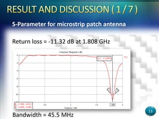
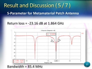
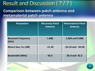
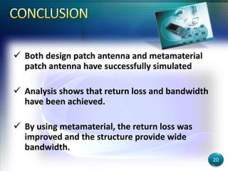
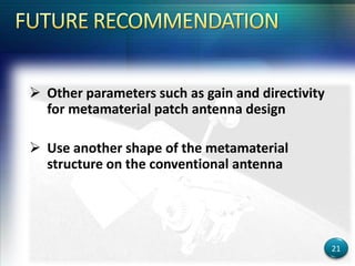


This document describes the design and simulation of a rectangular patch antenna and a metamaterial patch antenna for mobile applications. It presents the objectives, introduction, simulation process, results and discussion, and conclusion. The parameters and dimensions of the designed patch antennas are provided. The results show that the metamaterial patch antenna achieved improved return loss and wider bandwidth compared to the microstrip patch antenna. Future work could investigate other metamaterial structures or parameters of the antenna designs.